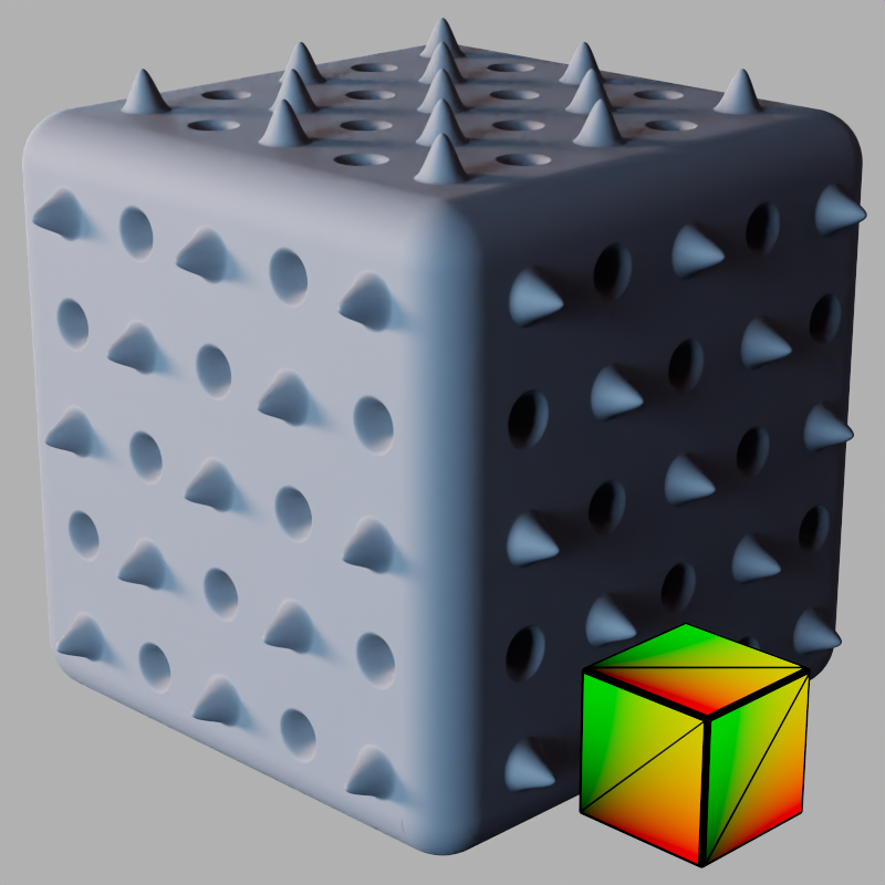
Geometry
|
|
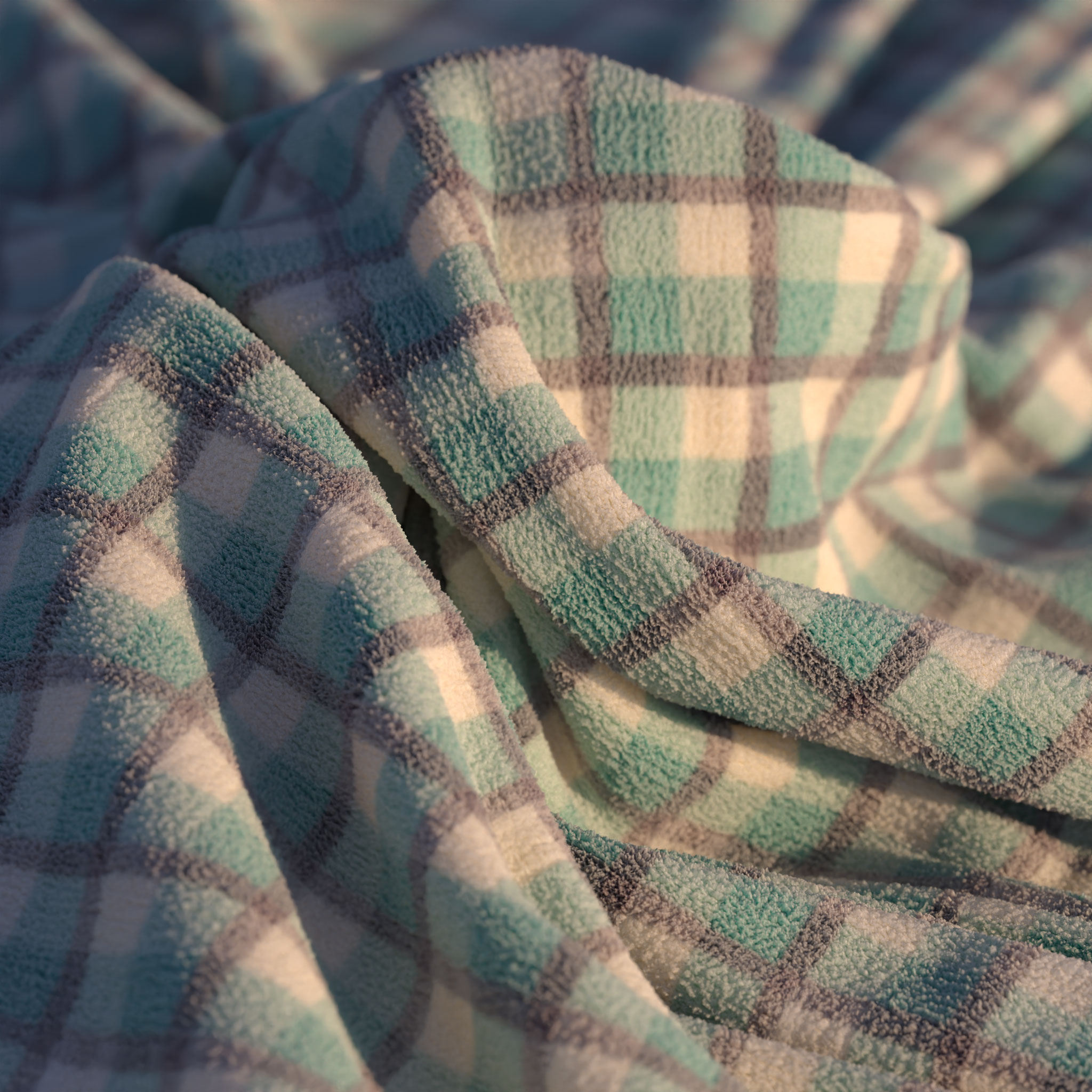
| Curly cloth texture from PolyHaven.com Cloth model by Fuchs & Vogel |
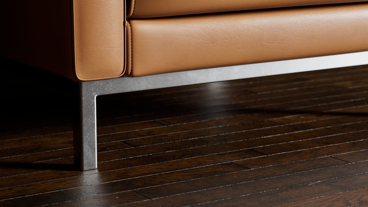
Sofa by Pavel Zoch Ground texture from PolyHaven.com |
Overview
Tessellation
Tessellation is a technique that can take a coarse, low-polygon mesh and render it completely smooth. Working with low-polygon meshes and letting Redshift subdivide at render time has certain advantages:
- Low-polygon meshes are easier to manage for animations
- The 3D program doesn't have to maintain large numbers of polygons in the scene which can be expensive on system memory
It can be more memory-efficient (which is important for GPUs) when combined with view-dependent and/or adaptive subdivision. Small or distant objects, for example, will look smooth enough with fewer subdivisions than objects that are close to the camera. Redshift supports screen-space adaptive and world-space tessellation for improved memory usage.
Vertex and Texture Displacement
Displacement is used to add extra geometric detail to a mesh through shader networks, i.e. textures and noise shader nodes that displace the base geometry. Redshift supports two types of displacement, Vertex Displacement and Texture Displacement.
Vertex Displacement is the most capable and compatible form of displacement, though it has low interactivity. It's called Vertex Displacement because the actual vertices of the mesh are moved around to simulate geometry detail based on the displacement texture. More vertices equal more displacement detail, but this means either your base mesh needs a lot of geometric detail or you will need to tessellate it sufficiently at render time. Vertex displacement supports height field (displacing along the vertex normal) and vector displacement maps (in object or tangent space). Importantly, any displacement detail that can't be represented with the current tessellation settings can instead be represented using bump mapping – therefore a good level of surface detail can be present when using Auto Bump Mapping even with fairly low tessellation.
Texture Displacement is great for interactivity and quickly adding detail to large low-poly areas like bricks on walls or detail on a large ground plane. It's a form of tessellation free displacement and it's called Texture Displacement because it requires baking the displacement result down to a texture at render time - the resolution of that baked texture is directly responsible for how detailed the displacement is. Higher bake resolutions equal more displacement detail, but even though it's baked more detail will slow renders down so it's always worth finding a good balance.
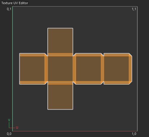
Texture Displacement requires a good UV unwrap with no overlapping UVs.
Texture Displacement supports Bake Resolutions from 64 x 64 all the way up to 16k x 16k. In some limited scenarios the "Smart Bake" feature can be used with a UV Context Projection node for effective bake resolutions much higher than that by baking one tile at full resolution and repeating that the requisite number of tiles. For more information, please see the Smart Bake parameter on this page below.
Use a Color Layer node to mix displacement textures with Texture Displacement. Displacement Blenders are not compatible with Texture Displacement.
Each have their strengths and weaknesses.
-
Vertex Displacement
- Advantages
- Best all around displacement type
- Supports Height field and Vector displacement
- Doesn't require a UV unwrap
- Can go out of core
- Disadvantages
- Slow interactivity
- High tessellation can be very slow
- Displacement quality is tied to mesh detail
- Requires more memory for equivalent Texture Displacement quality
- Advantages
-
Texture Displacement
- Advantages
- Great for adding detail to simple surfaces like walls and ground planes
- Fast interactivity
- Displacement is not tied to mesh detail
- Requires less memory for equivalent Vertex Displacement quality
- Disadvantages
- Requires a good UV unwrap and may reveal seams
- Complex shading features like SSS and Transmission can be very slow
- Baked textures can't go out of core
- Doesn't support Vector Displacement
- Advantages
Examples
Getting Started
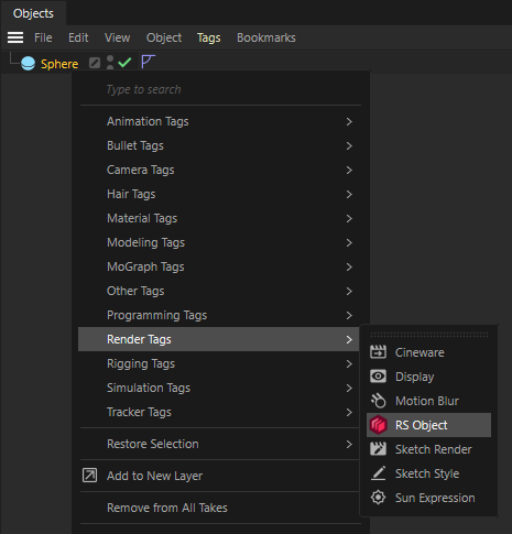
The object Tessellation and Displacement options are part of the Redshift Object Tag. In the Object Manager, right-click on an object and select the Redshift Object Tag from the Render Tags category.
The Tessellation and Displacement settings are effective on the object that hosts the Redshift Object Tag as well as any child objects.
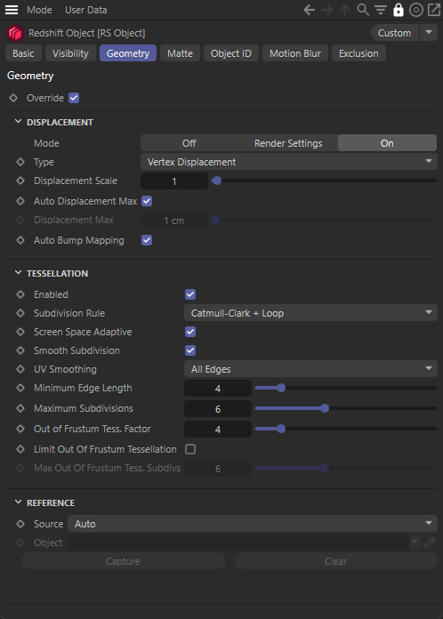
After selecting the tag, and navigate to the Geometry tab. To activate the settings check the Override option.
Texture Displacement
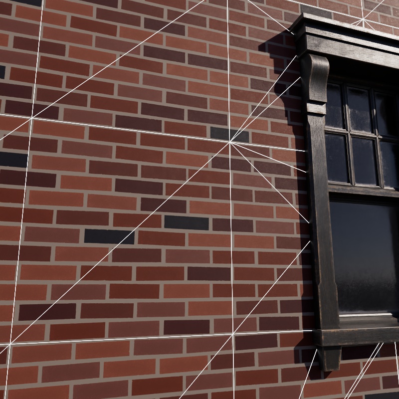
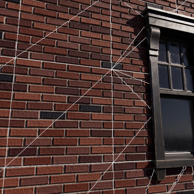
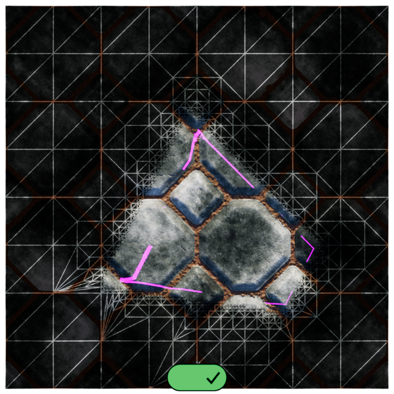
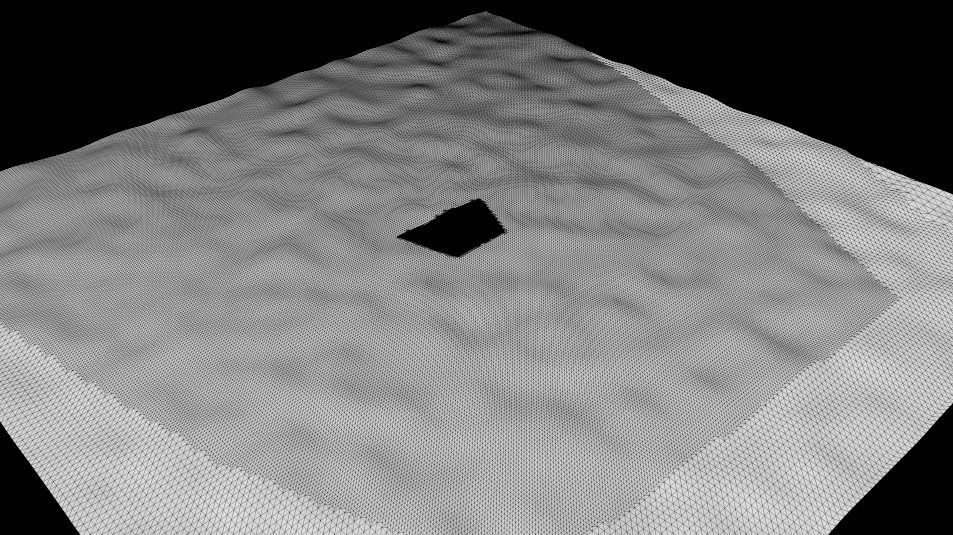
Texture Displacement works great when adding detailed geometric detail to objects like flat walls and ground planes. Just set up a material with displacement, set it to use Texture Displacement and adjust the Bake Resolution.
In the example below, the low polygon flat wall uses a brick texture to add high quality Texture Displacement.
|
|
| Brick wall without displacement |
Brick wall with Texture Displacement |
| Window model from PolyHaven.com | |
Texture Displacement is great for adding detail to surfaces but it requires extra care to make sure everything works correctly. The most common issues that crop up when using Texture Displacement are covered below.
Split Normals
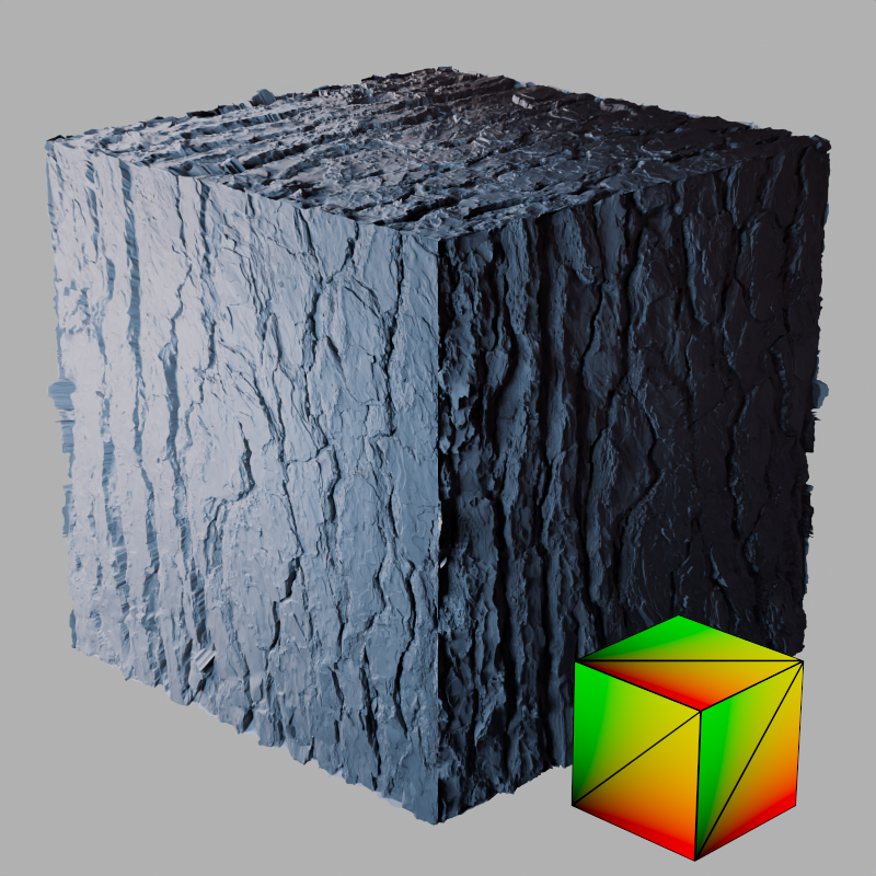
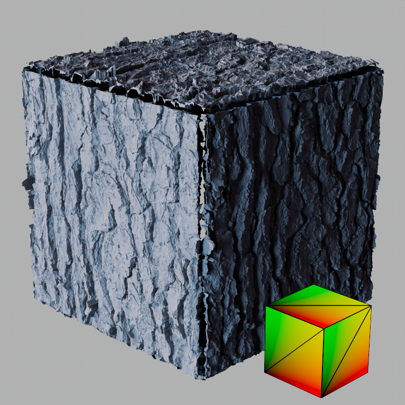
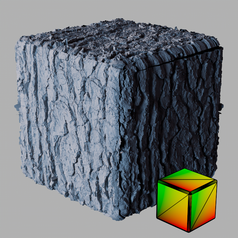
Texture Displacement, can run into trouble with complex geometry and even deceptively simple models. Take a cube, it poses a challenge because of split normals due to its hard edges. When a single vertex has multiple normals assigned to it - like the corners of a cube - it is likely to result in holes in the object. This is because rays fail to intersect with the surface since there is no surface between the normals.
By default Redshift avoids this issue by using the "Smooth Normals" mode for the Edge Handling option, this overrides and smooths all surface normals when using texture displacement. Below is a default cube from Cinema 4D using texture displacement. The first image uses Smooth Normals which keeps the cube from splitting apart. The second image uses Vertex Normals and the default phong angle of 40°, seams appear between each side of the cube because of the split normals at each vertex. The cube has no subdivisions and each face is unwrapped and placed directly on top of each other in the unwrap. Note, in the examples below, the small cube in the bottom right shows the UVs and wireframe for that example.
|
|
| Edge Handling: Smooth Normals Phong Angle: 40° |
Vertex Normals 40° |
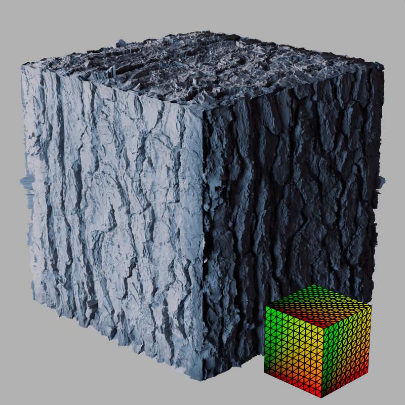
When using the "Vertex Normals" mode there are two main options to resolve this, either adding support loops like a rounded edge or increasing the phong angle. Adding rounded edges works since it decreases the difference between vertex normals by spreading the angle transition across more vertices while increasing the phong angle just smooths out the vertex normals.
In the first example the phong angle is left at the default 40° but the edges are rounded with a bevel as seen in the wireframe. In the second and third examples the phong angle is increased to 90°, this does a good job of fixing up the seams. However, in the third example it's worth noting that the lack of subdivisions on the default cube can cause shading issues so adding some improves the result.
|
|
|
| Default Cube + rounded edges Phong Angle: 40° |
Default Cube 90° |
Default Cube + subdivisions 90° |
Overlapping UVs
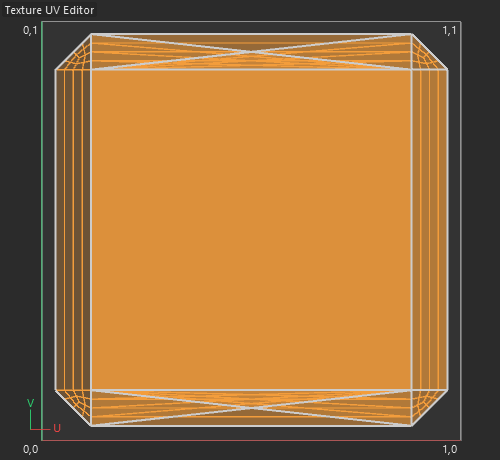
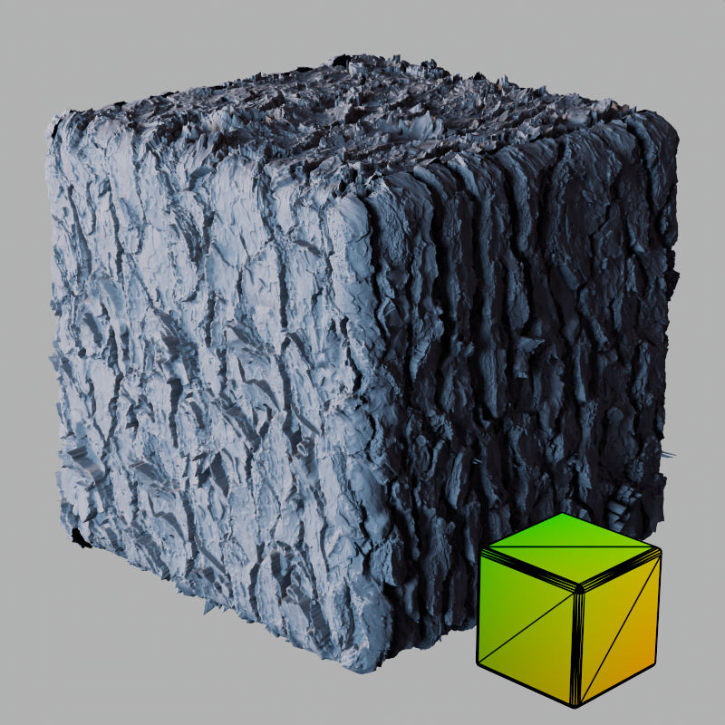
The story of the default cube is not over because a good UV unwrap is very important for Texture Displacement. Adding rounded edges helped reduce the seams but there are still some prominent gaps in the mesh because of overlapping UVs. In Cinema 4D the default cube's UVs are all stacked on top of each other, this causes severe issues for Texture Displacement which is reliant on baking the displacement result to a texture. When UVs are overlapping a unique texture can't be baked for each part of the object.
In the first example we see the default cube with it's overlapping UVs, in the upper right there is a gap in the mesh and stretched displacement. In the second example the cube is unwrapped so that all six sides have their own unique area. There are still seams but the stretching is fixed and the seams are much less prominent.
|
|
|
|
|
| Default Cube + rounded edges UV Unwrap: Overlapping |
Default Cube + rounded edges Overlapping |
Cube + rounded edges Non-overlapping |
Cube + rounded edges Non-overlapping |
You have to activate this option to be able to use Tesselation or Displacement with this object.
The Tessellation and Displacement settings are effective on the object that hosts the Redshift Object tag as well as any child objects.

By default, all objects start in the "Render Settings" displacement mode. When an object uses this mode, displacement is controlled by the "Global Displacement" options found in the Global tab of the Render Settings. This allows you to easily control displacement throughout the scene from one centralized location. When Global Displacement is enabled, any object using the "Render Settings" mode enabled displacement. When Global Displacement is disabled, any object using the "Render Settings" mode disables displacement. Setting the mode to "On" or "Off" overrides the Global Displacement behavior.
- Off: Displacement is disabled for that object.
- Render Settings: Displacement is controlled by Global Displacement in Render Settings. (default)
- On: Displacement is enabled and controlled locally by the displacement settings on the object.
|
|
| Displacement: Off |
On |
Sets the displacement type to Vertex or Texture Displacement.
Vertex Displacement is the most capable and compatible form of displacement, though it has low interactivity. The quality of Vertex Displacement is be managed by controlling the mesh detail and tessellation level.
Texture Displacement is great for interactivity and quickly adding detail to large low-poly areas like bricks on walls or detail on a large ground plane. Texture Displacement is easy to control displacement quality by adjusting the Bake Resolution and is not dependent on mesh detail.
For more information, please see this section.
Scales the displacement results by increasing or decreasing the displacement.
Displacement Scale can also be controlled in the Displacement shader node itself, as a matter of fact, the final displacement result is the product of the Displacement Scale in the Redshift Object settings multiplied by the Scale set in the shader node. For example, a Redshift Object Displacement Scale of 3 with a shader Displacement Scale of 1 results in a total scale of 3 and, when using Vertex Displacement, the Displacement Max would also need to be set to 3 in order to accommodate for this.
Being able to adjust the displacement scale at the object level allows you to have different scales for different objects that use the same material. It is generally recommended to leave one of these values at 1 for simplicity, be careful not to double up your displacement scale.
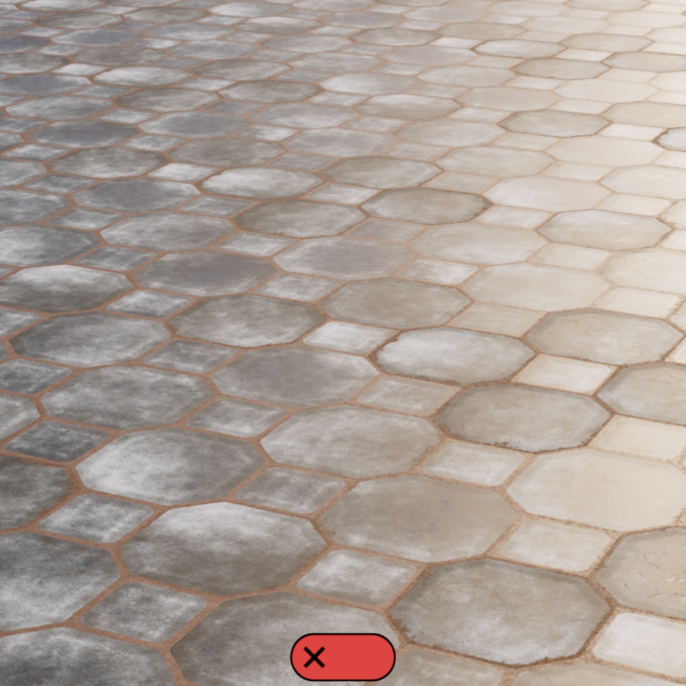
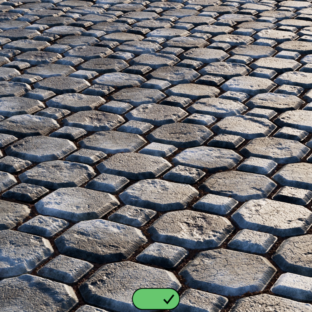
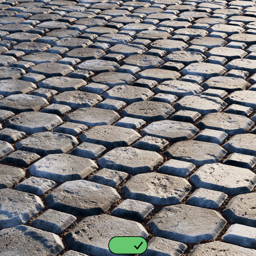
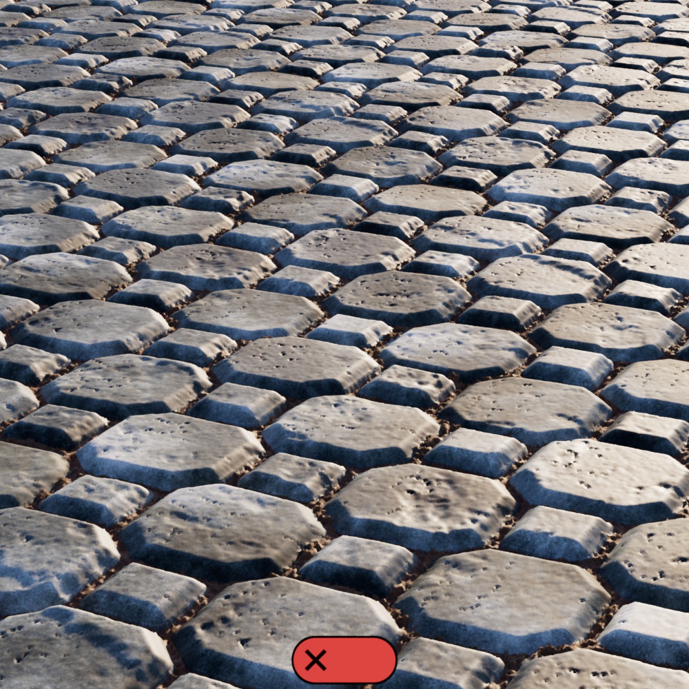
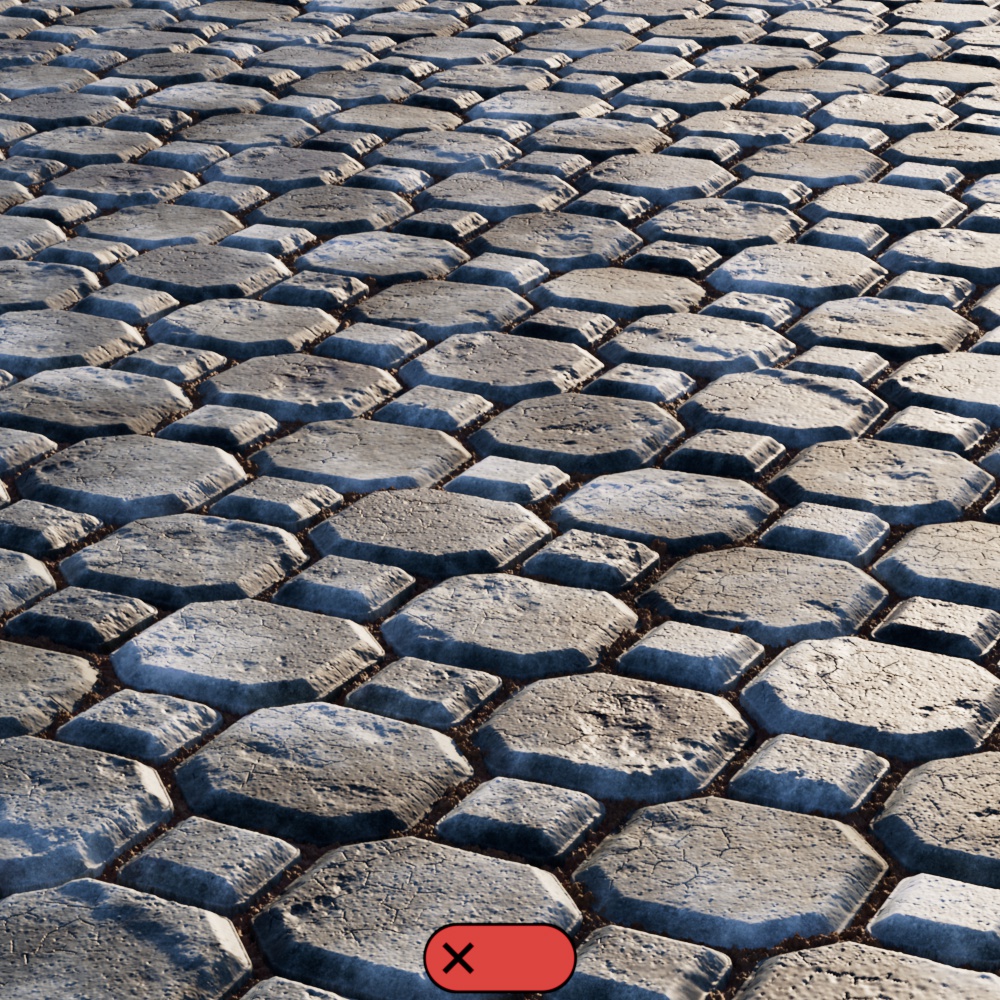
In the examples scenes below, one is a smooth black to white gradient ramp displacing a small yellow plane and the other is a paving stones texture displacing a large ground plane — in both examples the Maximum Scale value is animated from 0 to a value higher than the Displacement Max limit. Note how the displacement retains its overall form, looking more or less extreme depending on the scale, it isn't until it hits the Displacement Max limit that it gets cut off. In the scene with the yellow plane you can see displacement is capped at a Displacement Max of 2.9 scene units, just under the top of the third blue bar which is 3 scene units tall.
| Displacement Scale: 0 - 4 Displacement Max: 2.9 Vertex Displacement |
0 - 2 1.5 Vertex Displacement |
Only used with Vertex Displacement
When enabled, by default, the Displacement Max is calculated automatically based on the textures used for Displacement. When disabled, Displacement Max must be manually defined below.
Only used with Vertex Displacement when Auto Displacement Max is disabled.
Sets the limit on the highest distance in scene units that a vertex can be displaced.
For example, if you are adding two displacement textures together and each Displacement Shader has a scale of 1 scene unit, combined they can displace the vertices by 2 scene units, so a setting of 2.0 should be used for Displacement Max. If Displacement Max is set too low, the displacement result will be clamped and it will be cut off at a 'ceiling'.
On the other hand, if this value is set too high, there won't be any visual artifacts but performance could suffer because the Displacement Max value also has an impact on tessellation results. Increasing the Displacement Max value is similar to increasing an objects bounding box, the larger an object's bounding box becomes the more likely it is to enter the camera frustum which would trigger tessellation to occur. This might not be necessary as Redshift does not know if the bounding box actually needs to be that large so it will err on the side of caution and tessellate the object. Therefore, it is recommend to use a value that is as low as possible. Unfortunately, due to flexible nature of shaders, it's not currently possible to compute this value automatically. Settings similar to this can be found on other renderers, too, where they might be called "bounds padding" or "min/max bound".
In the example scenes below, one is a smooth black to white gradient ramp displacing a small yellow plane and the other is a paving stones texture displacing a large ground plane — in both examples the Displacement Max value is animated from 0 to a value higher than strictly necessary. The Displacement Scale listed under each example represents the lowest value necessary to displace the objects without clamping. In the scene with the yellow plane, the three blue bars are 1, 2, and 3 scene units tall. Note how the displacement appears cut off, it plateaus until Displacement Max meets or exceeds the Displacement Scale and once it exceeds the 3 unit bar there is no benefit to be gained. If your Displacement Scale is animated then Displacement Max would need to be set high enough to allow for the full range of displacement.
| Displacement Max: 0 - 4 Displacement Scale: 3 |
0 - 1 0.5 |
| Paving Stones Substance 003 textures from AmbientCG | |
Only used with Texture Displacement
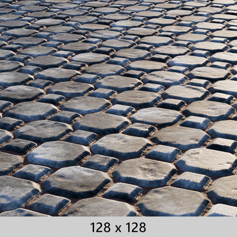
Controls the resolution for the baked displacement texture used by Texture Displacement. Higher resolutions result in higher quality displacement but take longer to bake and render.
Baked textures cannot go out of core, so it's important to find the right balance for your scene. Don't set the Bake Resolution unnecessarily high.
When Smart Bake is enabled, this controls the maximum baking resolution but Redshift automatically lowers the Bake Resolution if set too high. For example, if Smart Bake is enabled:
- When the displacement texture is 4k but the Bake Resolution is 8k then Redshift will only bake out at 4k.
- When the displacement texture is 4k but the Bake Resolution is 1k then Redshift will only bake out at 1k.
When a procedural texture is used with displacement the full Bake Resolution is always used.
|
|
|
|
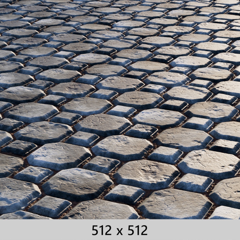
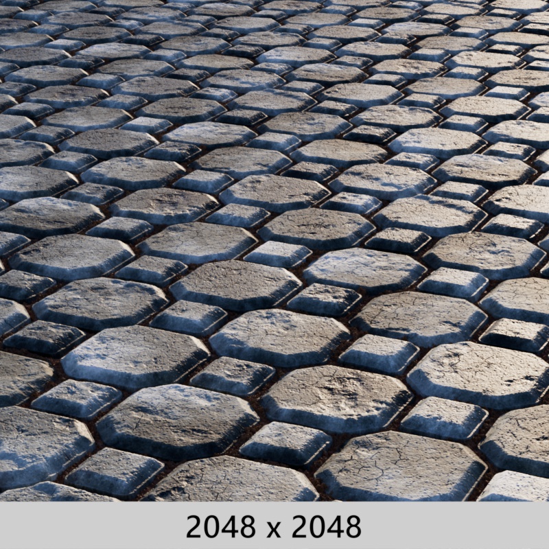
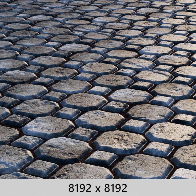
| Bake Resolution: 128 x 128 Render Time: 51s |
Bake Resolution: 512 x 512 Render Time: 1m 11s |
2048 x 2048 2m |
8192 x 8192 2m 45s |
Only used with Texture Displacement
When enabled, Redshift optimizes baking when tiling using a UV Context Projection node. Instead of baking each tile into the displacement texture, one tile is baked at full resolution and repeated the requisite number of tiles. Smart Bake makes the biggest difference for objects that require heavy tiling and are already effectively unwrapped. This makes it best suited to ground planes and something like a blanket with a simple 0-1 UV unwrap for the entire object. The ground plane can be uneven and the cloth can be folded as long as the UVs themselves are ideal for seamless tiling.
Requirements:
- Use UV Context Projection node connected to Material Output or Displacement node (Not connected directly to Texture)
- Only works with Square Tiling
- Hex Tiling is not compatible with Smart Bake and will ignore it automatically
In C4D, you can also use Smart Bake straight through the material tag without the need for a UV Context Projection node or the RS Object tag.
Note: Adjusting the tiling using the "Scale" parameters on the Texture Sampler will not have the same smart effect.
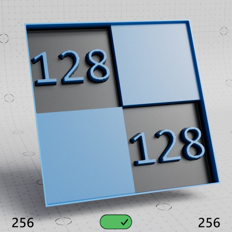
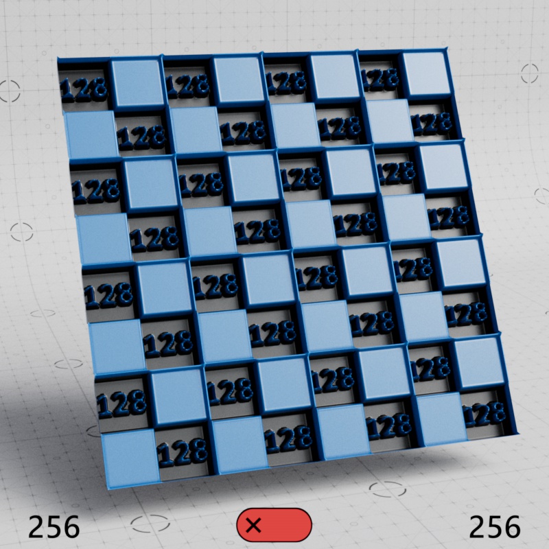
Take this example with a 256x256 checkerboard texture, each square in the texture is 128x128 pixels. First let's look at a baseline where Smart Bake makes no difference, a 1x1 tile of the texture. In the example images below, the number in the bottom left shows the actual "Bake Resolution" while the number in the bottom right shows the effective bake resolution after taking into account how many times the baked texture is tiled when Smart Bake is enabled. In this first example, both examples look the same because the texture isn't being tiled at all so Smart Bake makes no difference.
|
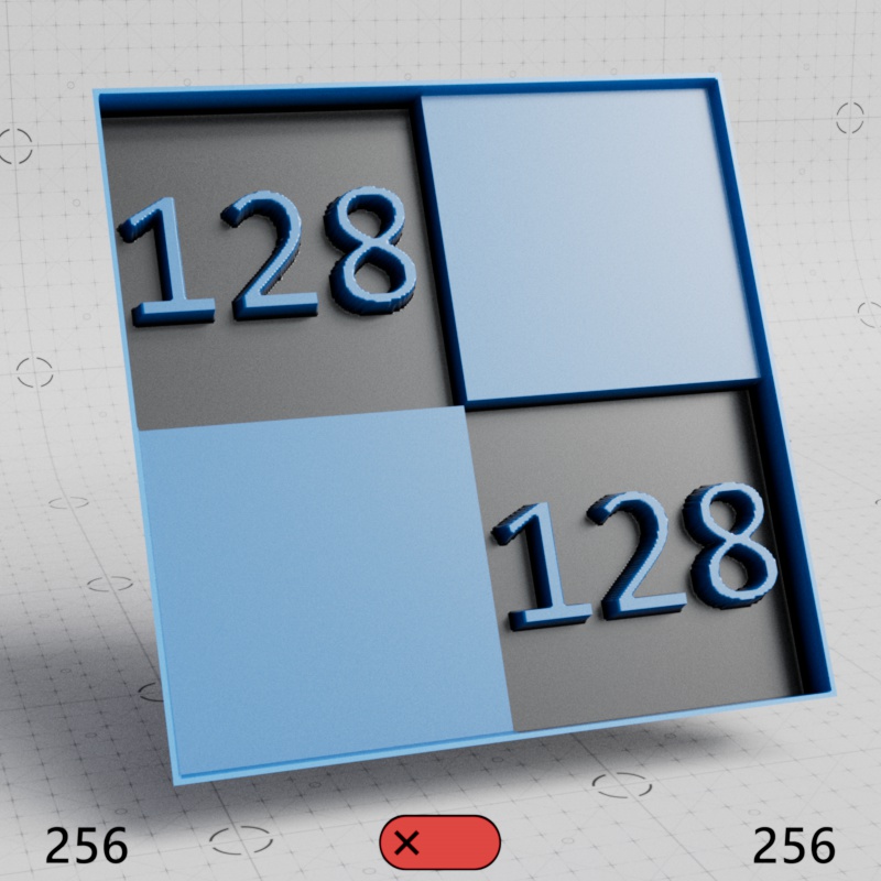
|
| Smart Bake: Enabled Bake Resolution: 256 Effective Resolution: 256 |
Disabled 256 256 |
But when we start tiling the texture the benefit becomes clear, here the texture has 4 tiles (2x2). With Smart Bake you get effectively a 512x512 bake because the original tile was baked at 256x256 and tiled 4 times. Meanwhile, when Smart Bake is disabled, all 4 tiles are baked into a 256x256 texture and the displacement quality takes a massive hit at 1/4th the necessary resolution.
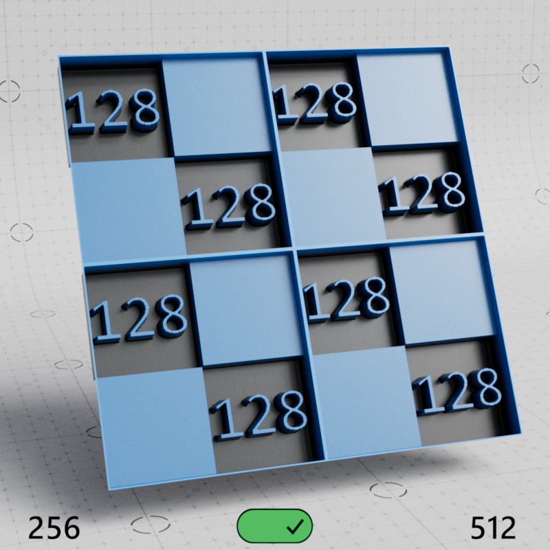
|
|
| Smart Bake: Enabled Bake Resolution: 256 Effective Resolution: 512 |
Disabled 256 256 |
It only gets worse the more we tile, here's a 16 tile (4x4) example. Now we're effectively getting a 1024x1024 resolution bake for displacement quality but Redshift is still only baking a single tile at 256x256. The Smart Baking disabled example is still trying to pack all 16 tiles into the same 256x256 bake.
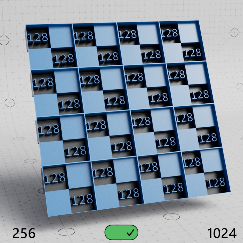
|
|
| Smart Bake: Enabled Bake Resolution: 256 Effective Resolution: 1024 |
Disabled 256 256 |
So, for example, let's say you have a ground plane with a 1k texture that repeats 10 times and are using a Bake Resolution of 2k.
-
With Smart Baking disabled the texture is tiled 10x10 times inside a 2k baked texture. This would greatly sacrifice displacement quality because the original tile has a resolution of 1k, so the most optimal bake resolution would be a 10k x 10k texture to account for all of the tiles.
-
With Smart Baking enabled the texture is baked once at only 1k because Smart Bake knows the source texture is only 1k. The baked result is then tiled efficiently 10x10 times, resulting in no loss of image quality, at effectively 10k x 10k resolution.
Note, the higher resolution displacement still impacts render times with Smart Bake enabled but it is much more memory efficient and baking time can be decreased.
When a procedural texture is used with displacement Smart Bake always uses the full Bake Resolution.
Only used with Texture Displacement
Controls how surface normals are handled with Texture Displacement, this is helpful for dealing with holes that may appear on geometry with hard edges.
- Smooth Normals - (Default) Overrides and smooths all surface normals. This option ensures that holes do not appear due to split normals when using Texture Displacement.
- Vertex Normals - Uses the surface normals as set on a mesh. This option should be used for objects that need special attention, holes produced by split surface normals will need to be manually adjusted per-mesh.
|
|

|
| Edge Handling: Smooth Normals Normal Angle: 0° |
Vertex Normals 0° |
Vertex Normals 40° |
Objects with very few subdivisions between angle changes may look strange when using Smooth Normals. This happens because there are not enough vertices to smoothly transition across as the displacement angle blends between each normal. It can be fixed by subdividing the geometry, beveling corners, or adding support loops.
In the first example below, a cube with no subdivisions uses "Smooth Normals" for Edge Handling, this pushes the displacement out at an angle as it converges toward the nearest vertex. In the second example the corners are beveled, this gives the displacement more vertices to transition between which allows the displacement to push straight out on the flat sides.
|
|
| Smooth Normals with no subdivisions | Smooth Normals with beveled edges |
Fine surface details require very high tessellation levels or high bake resolutions in order to look nice and sharp, otherwise the surface is likely to look soft and blurry. However, this means higher memory usage and frequently longer render times.
The Auto Bump Mapping option can be used to get around this by essentially using the displacement texture map to automatically drive bump mapping for increased detail. When using Vertex Displacement it may be possible to use less tessellation to achieve the same level of visual quality, or a lower Bake Resolution when using Texture Displacement.
- Off: Never use the displacement texture for additional bump mapping detail
- Displacement Only: Only use the displacement texture for additional bump mapping detail when the surface is actually being displaced.
- On: Always use the displacement texture for additional bump mapping detail.
When Auto Bump Mapping is set to "On", any connected displacement texture will add a bump mapping effect - even when displacement is disabled on the object.
This can be helpful when setting up materials that are used across a variety of situations. For example, sometimes the material might take center stage and require displacement, where as other times it may sit in the background and displacement would be a waste of performance. When the material is used in the background it still receives bump mapping even without displacement, and there's no need to wire up a separate bump map node just for that effect.
In the examples below, note how the first two images use the same number of subdivisions but when Auto Bump Mapping is enabled the detail level looks much higher. The third image is provided for reference, it has a higher subdivision level that results in greater detail but it uses more then double the amount of memory since it has to generate and displace many more vertices. These examples use Vertex Displacement but the use case is the same for Texture Displacement.
In some scenarios, like when using extreme displacement scales, Auto Bump may result in artifacts and should be disabled.
|
|
|
| Auto Bump Mapping: On Max Subdivisions: 5 |
Off 5 |
Off 7 (for reference) |
Enables or disables subdivision.
Redshift supports two algorithms for polygon subdivision: Catmull-Clark and Loop. Catmull-Clark can be used with quads or triangles but the Loop method only works with triangles.
The Subdivision Rule parameter controls how Redshift subdivides your mesh from the following options.
-
Catmull-Clark + Loop - The Catmull-Clark method is used to subdivide all quads while the Loop method is used to subdivide all triangles.
-
Catmull-Clark Only - The Catmull-Clark method is used to subdivide all quads and triangles, each triangle is split into three quads. This should only be used when Redshift is combined with other software that does not support Loop subdivision.
|

|
| Subdivision Rule: Catmull-Clark + Loop | Catmull-Clark Only |
The Screen Space Adaptive parameter controls how polygons are subdivided by changing the unit of measurement used by the Minimum Edge Length parameter. It might be helpful to think of the Screen Space Adaptive parameter as a subdivision mode selector.
When enabled, polygons are subdivided based on their measured edge length in pixels in the final render — hence, Screen Space Adaptive. When disabled, polygons are subdivided based on their measured edge length in scene units — in this case, subdivision takes place in World Space.
On this documentation page, "Screen Space mode" or "Screen Space subdivision" will be used to refer to tessellation when Screen Space Adaptive is enabled and "World Space mode" or "World Space subdivision" will be used to refer to tessellation when Screen Space mode is disabled.
-
Screen Space mode:
-
Advantages:
-
Subdivision is highly adaptive and can be much more efficient
-
Able to limit tessellation for objects outside of the camera frustum
-
-
Disadvantages:
-
Results can be inconsistent and change based on many factors like render resolution
-
May be unstable in motion
-
Cannot be used with instancing
-
-
-
World Space mode:
-
Advantages:
-
More consistent
-
Stable in motion
-
Can be used with instancing
-
-
Disadvantages:
-
More likely to be heavy on GPU memory and render times
-
Cannot limit tessellation for objects outside of the camera frustum
-
-
In Screen Space mode polygons are subdivided while their edge length measures longer than the number of pixels set by the Minimum Edge Length. For example, if the Minimum Edge Length is set to 10 then all polygon edges that measure longer than 10 pixels will be subdivided until the Maximum Subdivision level is hit or the newly subdivided edge length measures less than 10 pixels — whichever comes first.
In World Space mode polygons are subdivided while their edge length measures longer than the number of scene units set by the Minimum Edge Length parameter up to the Maximum Subdivision level. For example, if the Minimum Edge Length is set to 2 then all polygon edges that measure longer than 2 scene units will be subdivided until the Maximum Subdivision level is hit or the newly subdivided edge length measures less than 2 scene units — whichever comes first.
Screen Space subdivision is adaptive where as World Space subdivision is effectively static — the only time subdivisions will change in World Space mode is if the Minimum Edge Length is changed or the actual geometry changes in size. However, in Screen Space mode there are many ways to change how long an edge measures in pixels. For example, moving an object closer or farther from the camera, changing the render resolution, the camera zooming in or out, and an object scaling up or down could all trigger subdivision changes.
| Screen Space Adaptive: Enabled (Screen Space mode) |
Disabled (World Space mode) |
There are upsides and downsides to this adaptivity. On the positive side screen space can be much more efficient, like only adding more detail to objects close to the camera while far off objects have less detail, leading to savings on GPU memory and processing time that can be significant. Screen Space subdivision is also uniquely able to limit the amount of tessellation on objects outside of the camera frustum which can heavily reduce GPU memory usage. This is an optimization World Space subdivision is not able to do, instead, World Space mode will always tessellate objects — onscreen or not — as long as they meet the requirements set by the Minimum Edge Length and Maximum Subdivisions. However, since the subdivision level of an object can change as it moves across the screen the transition between different subdivision levels may be too noticeable and undesirable — for this reason screen space subdivision is frequently better suited to still images or animations where the transition is not as easy to see.
| Screen Space Adaptive: Enabled (Screen Space mode) Vertex Displacement |
Disabled (World Space mode) Vertex Displacement |
Tessellation and Instancing
When a mesh is instanced in Redshift, adaptive tessellation is no longer supported. However, you can use fixed-rate World Space tessellation (and, subsequently, displacement too) by using the following settings:
- Use World Space subdivision (Disable the Screen Space Adaptive parameter)
- Set Minimum Edge Length to 0
- Set the Maximum Subdivisions to something reasonable
Please pay particular attention to the third point, as the default setting (6 subdivisions) is generally too high for fixed rate subdivision.
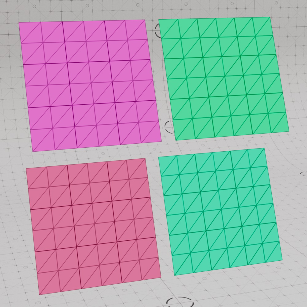
When enabled, objects are smoothly subdivided using the selected Subdivision Rule algorithm. This is great for smoothing out coarse low poly objects.
When disabled, objects are subdivided without smoothing using simple linear subdivision. This increases the polycount while retaining the original shape and silhouette of the object. If you are using Vertex Displacement on simple angular meshes (such as walls or a box) and don't want them turned into smooth objects, disabling smooth subdivision might be the right option for you.
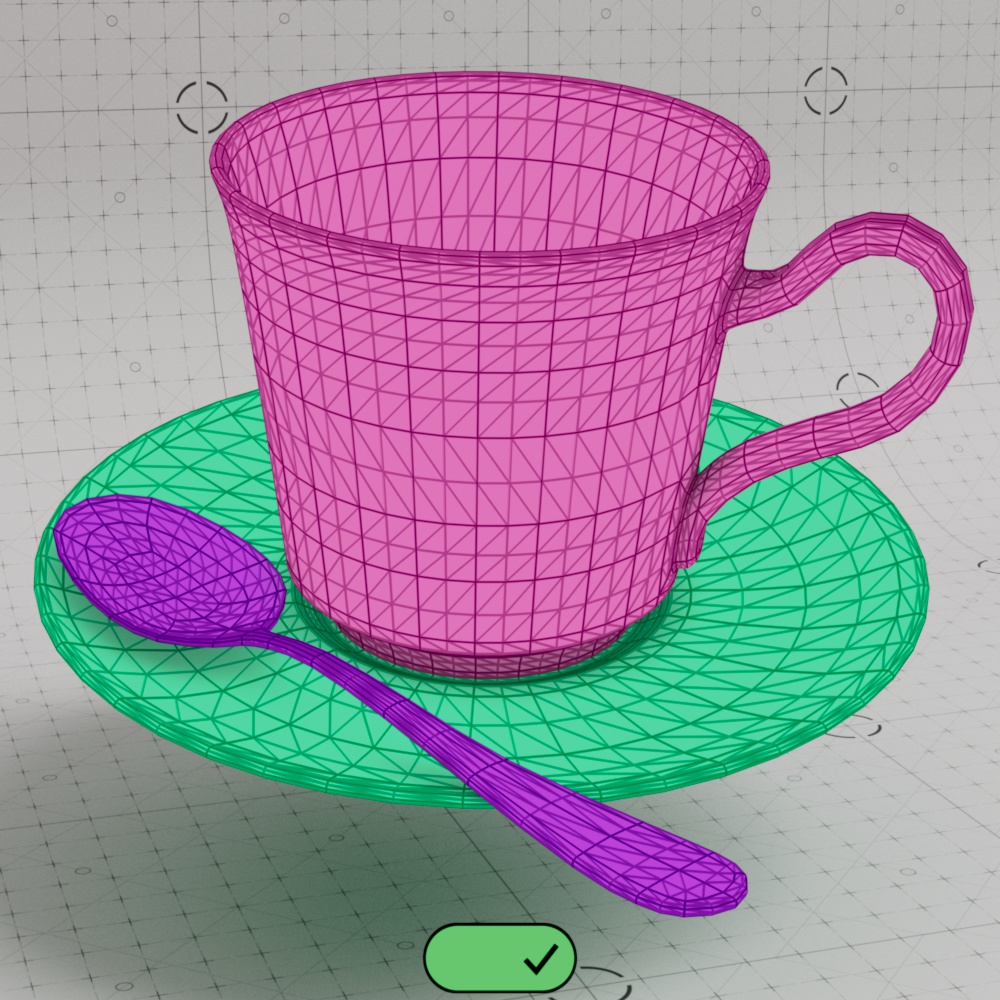
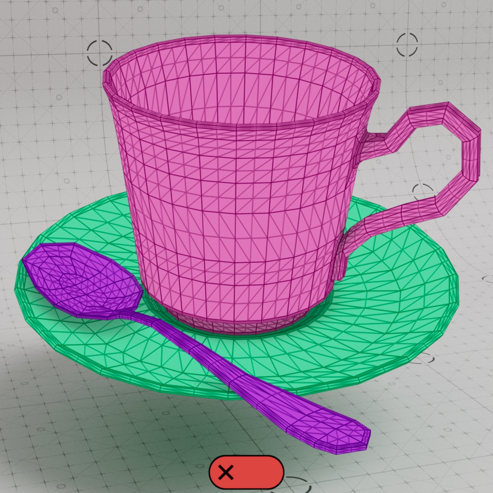
In the example below, note how the handle on the cup and the edges of the spoon are rounded off when Smooth Subdivision is enabled. When disabled, the objects are still subdivided but the actual shape does not change.
|
|
| Smooth Subdivision: Enabled |
Disabled |
| Teacup model by Raphael Rau | |
When "Smooth subdivision" is enabled, Redshift will smooth the vertex positions as well as the UV coordinates and tangent space vectors. Smoothing UV coordinates shifts the UVs to remove any 'zig-zagging' and 'UV breaks' during tessellation in order to maintain smooth UV-space curves. In the majority of cases, this is the desirable way to treat UVs. However, there are cases where strict UV layouts (such as when UV tiles are aligned to quads) need to be preserved and not smoothed. For this reason, Redshift supports enabling/disabling UV smoothing.
Minimum Edge Length (M.E.L.) controls when polygons are subdivided based on their edge length. If a quad or triangle has an edge that is longer than the Minimum Edge Length then it will be subdivided either until the Maximum Subdivision level is hit or until the edge is shorter than the M.E.L.. When the Screen Space Adaptive option is enabled (Screen Space Adaptive subdivision), the edge length is measured in pixels. When the Screen Space Adaptive option is disabled (World Space subdivision), the edge length is measured in scene units.
Lower values result in more subdivisions while higher values result in fewer subdivisions. When the M.E.L. is set to 0 tessellation will continue until it hits the maximum allowed subdivision level. When using Screen Space Adaptive tessellation there is an internal minimum limit of 0.5 pixels, this can result in polygons not actually reaching the Maximum Subdivision level. However, when using World Space subdivision, a M.E.L. of 0 will always hit the Maximum Subdivision level. Regardless of the subdivision mode, it is extremely important that the Maximum Subdivision level is set carefully otherwise render times may increase exponentially. Determining the right balance between polygonal density and render time by optimizing the Minimum Edge Length for your scene is an important step.
In the examples below you can see the difference in behavior between Screen Space Adaptive and World Space subdivision. The scene is comprised of five identical cubes measuring 4x4x4 scene units, each with only 6 polygons before any subdivision takes place. Since the Minimum Edge Length in Screen Space mode is measured in pixels note how polygons closer to the camera are consistently subdivided more often than polygons in the distance — this is common behavior as polygons nearest to the camera tend to have longer edges. However, as the Minimum Edge Length gets closer to 0 even the distant polygons reach the same level of subdivision since most edges now measure longer than the very short M.E.L..
By comparison, in World Space mode, the cubes changes subdivision levels at the same time since each cube is exactly the same size and Minimum Edge Length is calculated in scene units. World Space mode is the best way to hit specific subdivision levels consistently regardless of where the object is in the scene but this behavior also makes it easy to subdivide distant objects more than necessary, potentially wasting memory and render time in the process.
| Minimum Edge Length: 0 - 35 (pixels) Screen Space Adaptive: Enabled (Screen Space Subdivision) |
0 - 2 (scene units) Screen Space Adaptive: Disabled (World Space Subdivision) |
Next is a demonstration of Screen Space Adaptive and World Space subdivision with a ground plane using Vertex Displacement. On the right side of the screen is a wireframe overlay and a pink object that matches the current size of the Minimum Edge Length. In the Screen Space example there is a pink square that matches the M.E.L. in pixels from 0 - 30, and in the World Space example there is a pink cube that matches the M.E.L. in scene units from 0 - 0.5. The transition between subdivision levels is clearly visible in the Screen Space example, it moves up and down the ground plane from the large polygons in the foreground to the small ones in the background due to perspective. In the World Space example all of the geometry updates at the same time since the ground plane is made up of equally sized quads.
| Minimum Edge Length: 0 - 30 (pixels) Screen Space Adaptive: Enabled (Screen Space Subdivision) |
0 - 0.5 (scene units) Screen Space Adaptive: Disabled (World Space Subdivision) |
Sets the limit on the highest number of subdivision passes that can be applied to a tessellated object.
Subdividing a mesh happens in 'passes.' Each pass turns a single quad or triangle into four quads or triangles respectively and each pass is applied to the result of the previous pass.
For example:
- A setting of 1 will turn 1 quad into 4 quads
- A setting of 2 will turn 1 quad into 16 quads
- A setting of 3 will turn 1 quad into 64 quads
- A setting of 4 will turn 1 quad into 256 quads
- A setting of 5 will turn 1 quad into 1,024 quads
- A setting of 6 will turn 1 quad into 4,096 quads
- A setting of 7 will turn 1 quad into 16,384 quads
- A setting of 8 will turn 1 quad into 65,536 quads
The number of polygons can grow very quickly so the Maximum Subdivisions parameter should only be set as high as necessary for the look that you need. Sometimes increasing Maximum Subdivisions by just one level can make a frame take four times longer to render than the previous level or you might run out of system memory and not being able to finish rendering the frame at all. So if you took a mesh made up of 1,000 quads with a Maximum Subdivisions level of 8 it would become a 65 million quad mesh.
![]() This could take an extremely long time to generate and would consume lots of memory! For this reason, great care has to be applied when setting the Maximum Subdivisions and balancing the results with the Minimum Edge Length.
This could take an extremely long time to generate and would consume lots of memory! For this reason, great care has to be applied when setting the Maximum Subdivisions and balancing the results with the Minimum Edge Length.
| Max Subdivisions: 0 - 4 | 0 - 7 |
Out of Frustum Tess. Factor[0.00..+∞]
Only compatible with Screen Space Adaptive subdivision.
Out of Frustum (O.O.F.) Tessellation Factor allows objects that are outside the camera frustum (i.e. objects outside the camera view that are not directly visible) to be subdivided to a lesser degree. Higher values result in less subdivision outside of the camera frustum, while lower values result in more subdivision outside the camera frustum. As a result increasing the O.O.F. Tess. Factor can help save memory and reduce render times by performing fewer subdivisions on objects that are potentially less visually important. However, sometimes an object might be outside the camera frustum but still perfectly visible in a reflection or the object might be casting a well-defined shadow within the camera frustum. For such objects, lower values should be used and an Out of Frustum Tessellation Factor of 0.0 disables this optimization entirely. Additionally, the Minimum Edge Length parameter has an impact on O.O.F. subdivision too — lower Minimum Edge Length values push O.O.F. subdivision closer to maximum subdivision levels which reduce the effectiveness of this option, in such a case consider capping the O.O.F. subdivision level with the Limit Out Of Frustum Tessellation options.
In the examples below, a blue cube placed just outside of the camera view can be seen reflected in a mirror, note how subdivisions increase as the O.O.F. Tess. Factor gets closer to 0 in the first example but don't change at all while the Minimum Edge Length is set to 0 in the second example. Generating fewer subdivisions is more efficient as long as the result does not negatively impact the look that you are after.
| O.O.F. Tessellation Factor: 0 - 50 Minimum Edge Length: 30 |
0 - 50 0 |
In the previous examples you may notice how the upper left part of the cube always remains more highly subdivided, this is because that part of the cube is closer to the camera frustum bounds than the rest of it. In the example below you can see how moving the cube farther away from the camera reduces the subdivision level.
| O.O.F. Tessellation Factor: 30 Minimum Edge Length: 30 |
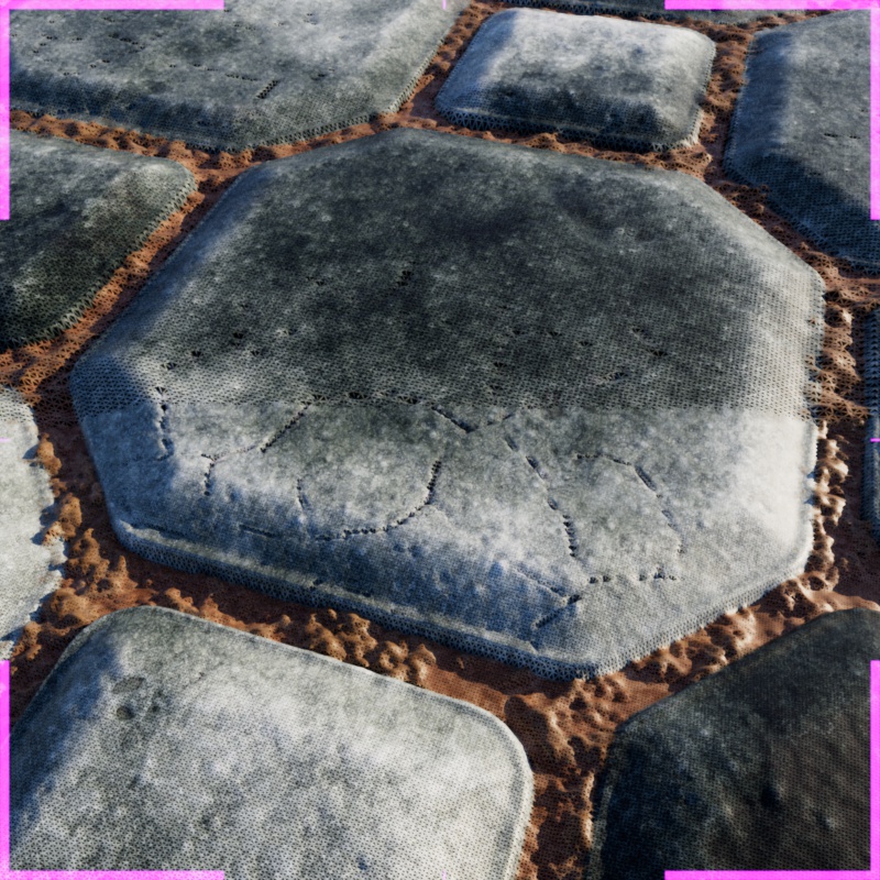
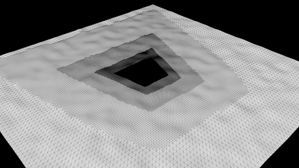
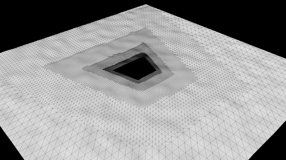
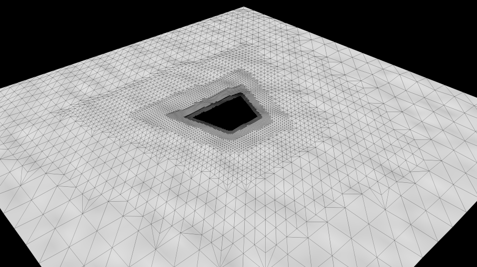
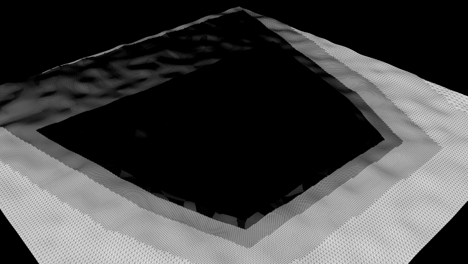
This effect can also be illustrated on a tessellated and displaced ground plane. Take the following scene with a single quad and Vertex Displacement, the camera is tilted down toward the plane from a close position. In the example images below the scene was rendered once from the camera, then the tessellation was frozen in the Render View, and the camera was pulled back to see the still frozen effect of the tessellation outside the camera frustum. As you can see, the polygons inside the camera frustum, outlined by a pink border, are tessellated the most. Polygons that are farther away from the camera frustum are subdivided less based on the Out Of Frustum Tessellation Factor.
|
|
| O.O.F. Tessellation Factor: 0 - 40 | Test scene render (for reference) |
When the camera is close to an object with Vertex Displacement you should be careful with the Displacement Max value because it is used to determine if a polygon is inside the camera frustum or outside of it. This is necessary because a polygon with high displacement might start outside the camera frustum before displacement but end up inside the frustum after displacement. Without this consideration the polygon would not receive the tessellation it needs to look right. When Displacement Max is too high Redshift might incorrectly "think" too many polygons are inside the camera frustum leading to a lot of subdivision outside the frustum.
In the example below, the Displacement Max value is animated from 10 to 100. 10 is the highest value necessary for this scene and raising it any higher than that results in unnecessary tessellation outside the camera view. This is a waste of resources and render time since those polygons are not visible which is why it is important to set Displacement Max only as high as necessary. If you need a high Displacement Max but are generating lots of unnecessary subdivisions off screen the Out Of Frustum Limit can be enabled and the polygons outside the camera view can be capped at a lower subdivision level as demonstrated in the last image.
|
|
| Displacement Max: 10 - 100 Out Of Frustum Limit: Disabled Max O.O.F. Tess Subdivs: 3 |
100 Enabled 3 |
Limit Out Of Frustum Tessellation
Only compatible with Screen Space Adaptive subdivision.
When Limit Out-Of-Frustum Tessellation is enabled, you can specify the highest number of subdivision passes that can be applied to objects outside the camera frustum with the Max Out-Of-Frustum Subdivs option. This setting is useful when increasing the Out-Of-Frustum Tessellation Factor still results in excessive subdivision. This condition can happen when the mesh is using Vertex Displacement that has a very high displacement scale. For a more detailed discussion on this, please see the relevant section below.
In the examples below, a blue cube placed just outside the camera view can be seen reflected in a mirror and the camera pans over until the cube comes partially into view. In both examples the cube has a Maximum Subdivision level of 4 and a Max Out of Frustum Tess. Subdivs level of 2. Note how the subdivision level does not change when Limit Out of Frustum Tessellation is disabled. However, when Limit Out of Frustum Tessellation is enabled the subdivision level changes depending on whether the cube is visible in the camera frustum or not. When the cube is directly visible the reflection of the cube also illustrates the higher subdivision amount and when it disappears from direct view the cube is limited by the lower maximum subdivision level
| Limit O.O.F. Tessellation: Disabled (default) Maximum Subdivisions: 4 Max O.O.F. Tess. Subdivs: 2 |
Enabled Maximum Subdivisions: 4 Max O.O.F. Tess. Subdivs: 2 |
In the next example, you can see the result of applying an Out of Frustum Limit to an off-screen object casting a shadow on a plane in the camera view. When Limit O.O.F. Tessellation is enabled a five-sided torus is limited to 0 subdivisions resulting in a very jagged shadow compared to the smooth torus when it is disabled and allowed to subdivide up to the Maximum Subdivision level of 4.
|
|
| Limit O.O.F. Tessellation: Disabled (default) Max O.O.F. Tess. Subdivs: 0 Maximum Subdivisions: 4 |
Enabled Max O.O.F. Tess. Subdivs: 0 Maximum Subdivisions: 4 |
Max Out Of Frustum Tess. Subdivs[0..16]
Only compatible with Screen Space Adaptive subdivision and Limit Out of Frustum Tessellation.
Sets the limit on the highest number of subdivision passes that can be applied to objects outside of the camera view.
In the examples below, a blue cube placed just outside the camera view can be seen reflected in a mirror and the camera pans over until the cube comes partially into view. In both examples the reflected cube can be seen matching the subdivision level of the part of the cube when it is directly visible, however, the off-screen part of the cube is subdivided less based on the Max Out of Frustum Tess. Subdivs value.
| Max O.O.F. Tess Subdivs: 3 | 1 |
Out Of Frustum Tessellation
The following images show what "out of frustum tessellation factor" does for polygons that are outside the camera frustum.
The test scene is simple: it's just a quad with a mild fractal displacement. The camera is looking at the quad (slightly tilted down) from a close position.
Scene setup
We use a wireframe shading node so we can visualize tessellation.
In the images below, we rendered once from the camera, then we froze tessellation in the RenderView and then we "pulled the camera back" so we could see the effect of polygon tessellation outside the camera frustum. As you can see, the polygons that are inside the camera frustum are tessellated the most. Polygons that are away from the camera frustum are tesselated less and depending on the "out-of-frustum tessellation factor". The farther away a polygon is from the camera frustum, the less it gets tessellated.
|
|
|
|
|
Out-of-frustum tessellation factor: 8 |
16 |
32 |
This setting should be used carefully! Even though a polygon is outside the camera frustum, it might be visible through a mirror or it might be casting a defined shadow inside the camera frustum! So, in these cases, making it tessellate less might make it look blocky/angular and generally too-low-poly in reflections or shadows!
While Out of Frustum Tess. Factor allows us to get tessellation under control and save on Redshift's memory usage and rendering speed, there does exist one case where it might prove ineffective: scenes with large displacements and the camera being close to the displaced geometry.
To explain: When you set up displacement in Redshift, you have to declare a Maximum Displacement setting. This setting tells Redshift that displacement can go up to a certain distance. This setting is also used by Redshift when it tries to determine if a polygon is inside the frustum or outside it. The reasoning behind that is that, if a polygon is going to be displaced ("moved") by a lot, it might actually be moved inside the camera frustum, even though it was originally outside the camera frustum. In other words, Redshift applies "conservative" tessellation when it comes to displaced polygons that might end up being inside the camera frustum.
When this happens, Redshift might incorrectly "think" that too many polygons are inside the camera frustum and it might, therefore, tessellate these polygons a lot!
To show this, we'll edit our scene and make Maximum Displacement several times larger. Notice how there is much more tessellation because Redshift now thinks that all the polygons outside the frustum could possibly end up inside the frustum!
Increasing "max displacement" produces much more tessellation
For these cases, the Limit Out Of Frustum Tessellation control should be used. In the picture below, we enabled it and set the "max out-of-frustum sudivs" to 5 (the mesh uses max subdivs 8). This means "If a polygon is outside the frustum, ensure it doesn't get subdivided more than 5 times".
Setting "max out-of-frustum subdivs" to 5 limits the tessellation
You can think of this setting as a "subdivision clamp".
These settings affect the fixation of some 3D shaders, such as Noise, on deformed objects. These shaders are often calculated based on the position of the object's axis system, which would lead to a change in the generated structures on the surface if the object were deformed. These options can establish a fixed relationship, e.g. between the point coordinates of the object and the 3D structure of the shader, and prevent the shader structure from slipping during deformation.
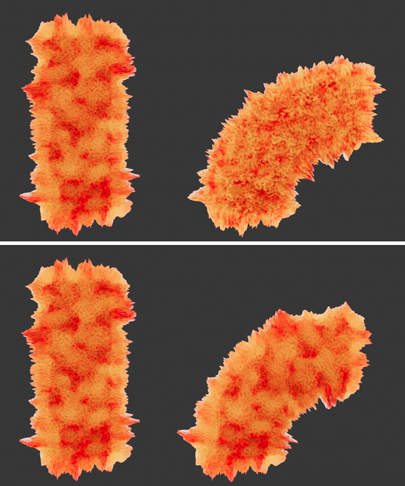 The top row shows the undeformed object on the left and the deformed on the right. It is especially obvious at the upper end of the deformed object that the deformation of the noise shader displacement has changed there (despite UVW mapping). The bottom row shows the same scene, this time with the Snapshot option and saved points and polygons.
Reference geometry is important for texturing objects when deformations are applied. When a reference object is not found or specified, textures can swim through objects as they are deformed. The Source parameter sets the reference behavior from the following options:
- Auto : Redshift tries to find the appropriate reference object automatically. If a deformer is applied to an object the geometry is automatically referencedbefore deformation.
- Object: Manually specify an object as the reference geometry. Useful when the object has changing topology.
- Capture: Use the captured geometry as reference. Incompatible with changing topology.
In all cases the reference object must have the same topology as the object the tag is applied to. If not, the reference is ignored.
When Source is set to "Object" the reference can be manually specified here.
When Source is set to "Capture" the reference object can be set by hitting the "Capture" button which uses the state of the currently selected object as the reference.
Polygon information for the currently captured object is printed below the Capture button.
In Snapshot mode, you can use this button to remove the point and polygon information of the current (undeformed) object from memory.