Node Editor Menu
Note that, depending on the Node Editor, different commands will be available. They are all described here.
Create menu
The Node Commander makes a similar functionality available as in the Content Browser’s asset list. You don’t have to use the mouse but simply have to press the C key and the list will open. However, the Node Editor must be active. You can also click on the Add Nodes button in the Node view.
In addition to the functions described for the asset list, the Node Commander also offers the following:
- The ESC key or click outside of the window will close the window (the filter icon order will be saved)
- The TAB key switches from the list to the Filter field
- Shift + TAB switches from the Filter field to the list
If you copy a value to the clipvoard using the Copy Value command, the Create Value Node from Clipboard command can be used to create a new Value Node with correctly set values..
This will copy a given port's current data state and fixate it in the Value Node. If the clipboard contains a value that comes from outside of Cinema 4D it will always be read in using the String data type.
Example: You used a classic object node to create geometry in the Node Editor. If you want to place this geometry into a Value Node, first create a Port Inspector for the geometry output (this should link to a Scene Node, otherwise nothing may be output at the port). Then execute the Copy Value command for this port. When the Create Value Node from Clipboard command is called up the complete geometry will be saved in the Value Node with the correct data type. The classic object node can then be deleted.
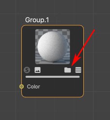
Creates an empty group for the current Node Material.
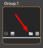
Click on the Folder icon or double-click on the Group Node to open the group.
What is a Group?
Groups are summary, parent Nodes that contain a network of Nodes (and/ or groups as well) The ports of Nodes in these groups can also be propagated outwards in order to feed values from Nodes outside of the group or to access values of Nodes within the group.
Groups can be converted to Assets and passed on.
You can also select multiple Nodes and group them using the following command.
Groups selected Nodes (see also previous command).
Ungroups grouped Nodes and deletes the Group Node. Connections are maintained - as well as outwardly, if possible.
Edit menu
These are the usual commands with which you can delete changes made in the Attribute Manager or undo/ redo functions. Contrary to the XPresso editor, moving or expanding Nodes is not included for these functions.
Here you can copy selected Nodes to the cache (for Cut, the Nodes will also be deleted) and Pasted in the Node Editor. Existing connections between the selected nodes will also be copied.
Selected Nodes will be duplicated, (including all existing connections).
Alternatively you can Cmd/Ctrl + click on selected nodes and move them. This will duplicate them automatically.
Selected Nodes will be deleted. Pressing the Backspace- or Del keys will do the same.
Selects or deselects all Nodes.
Selects all Nodes connected to the selected Node. This makes it easy to select a series of connected Nodes.
Here you can access specific Preferences settings for the Node Editor.
Using this command, a Scene Node setup can be converted to a common scene, which primarily offers access to the generated mesh that can in turn be edited using the normal Ciname 4D tools. To do so, open the Scene Nodes Representation: you will find all meshes under the Meshes Null object.
Furthermore, under Hierarchy, you will find all instances that reference the aforementioned meshes, arranged in a correct hierarchy. The hierarchy displayed in the Object Manager is a representation of that defined in the Node Editor.
Why instances? Scene Nodes generate almost all geometry internally as instances and will therefore be shown as such in the Object Manager.
Node menu
These commands can be used to show or hide the Node’s preview (in the upper area of each Node). The application’s Preferences menu has a Material tab in which a default setting defines if the preview for new Node creation should be visible or not. What good does it do to hide the preview since it actually offers valuable information. Well, for very extensive Node networks it can be very computationally intensive to update all previews when changes are made. In such cases it can be useful to hide the preview.
Furthermore, under Hierarchy you will find all instances that link to the previously mentioned meshes, arranged hierarchically. The hierarchy shown in the Object Manager is a representation of what is defined in the Node Editor.
Why instances? Internally, Scene Nodes generate practically all geometry as instances and are therefore displayed accordingly in the Object Manager.
Hide all Ports hides the port area for all selected Nodes, The connections are maintained. This is a purely optical effect, for example, to get a better overview of your setup. Calling up the Show all Ports command will reverse the effect.
Selected ports can also be defined as hidden with the Del key. The Show all Ports command will then not make these visible again. You will have to define the respective port as being visible via the Add Input command.
The funciton of the following two commands can also simply be accessed for each Node using this icon:
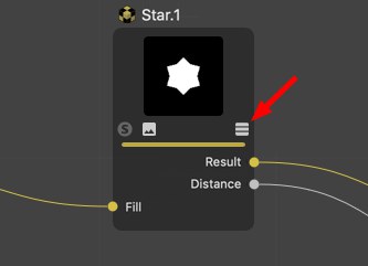
Only the ports with connections will be shown for the selected Node. All others will be hidden. This can be undone using the Show all Ports command.
In the Material Node Editor, the Solo Mode works as follows (Nodes don’t necessarily have a preview; these are, for example, useless for Nodes in the Scene Node Editor):
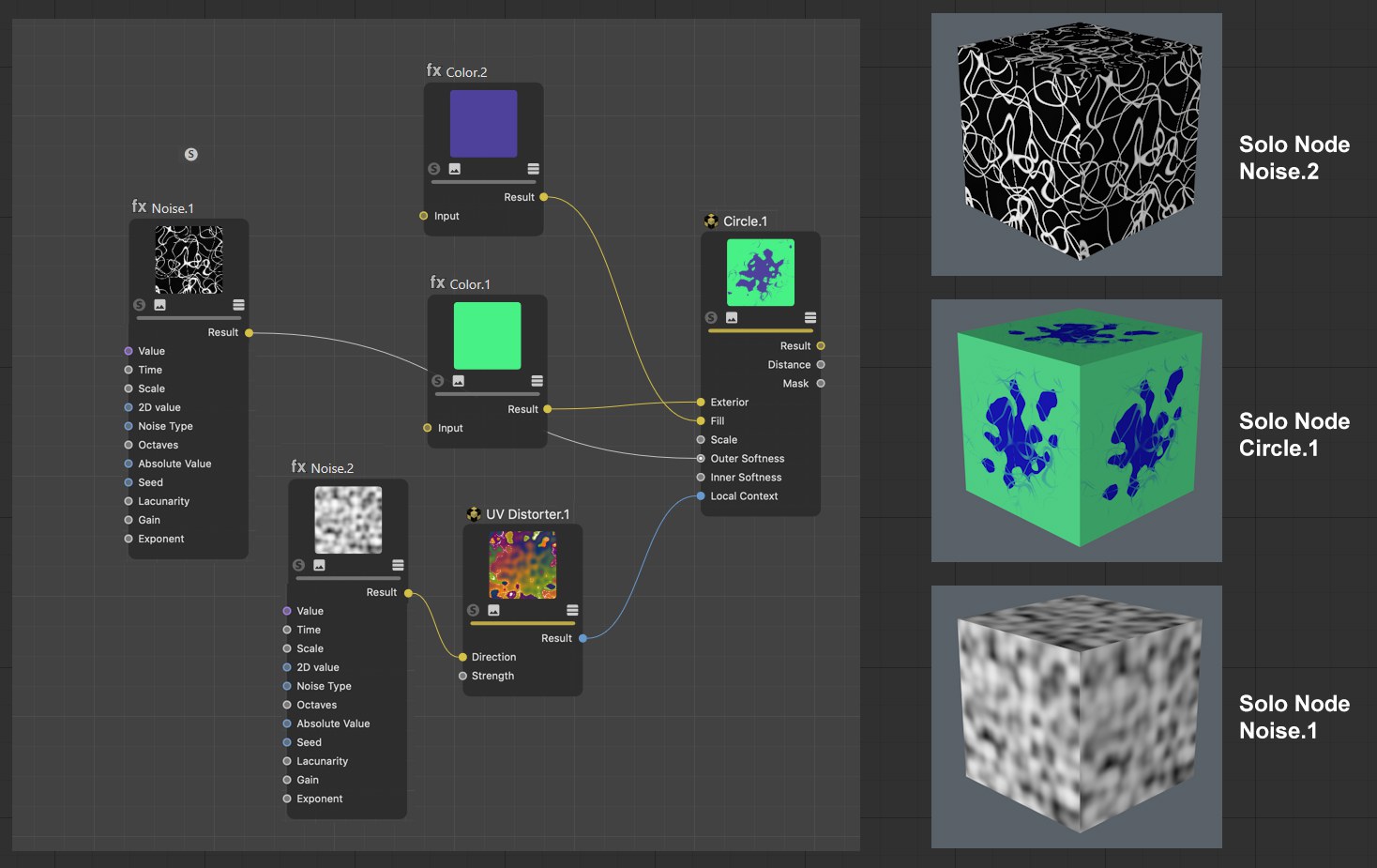 Different Nodes defined as Solo Nodes, rendered texture on a cube.
The enabled Solo Node mode omits all other Nodes. In the Node Editor view and for rendering, only the Nodes fed into the Solo Node and the Solo Node itself will be evaluated and displayed. This is, for example, very useful if your Node preview is too small because you can display or render the effect of individual Nodes at any scale.
Use this command for a selected Node (possibly with a selected output port: see also Solo port) or simply click on the Node’s S icon.
Logically, only a single Node can be a Solo Node. To exit the Solo Node function, call up the Set Solo Node / Port command or simply click again on the S icon.
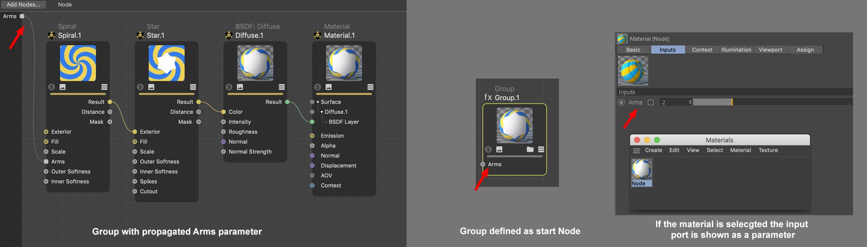
The Start Node works as follows in the Material Node Editor: Node Materials can be made up of very complex networks consisting of hundreds of Nodes. If you want to make minor changes to a material without diving too deeply into the Node Editor, one Node - a single Node per Node Material - can be defined as a Start Node. This Node’s inputs (and only this Node’s inputs) will be displayed in the Attribute Manager or the Material Editor’s Input tab when the material is selected.
If, on the other hand, you only want to display a few ports and you’re working with groups, propagate the respective ports from the group and define the Group Node as a Start Node.
Start Nodes will be marked with a green frame if unselected.
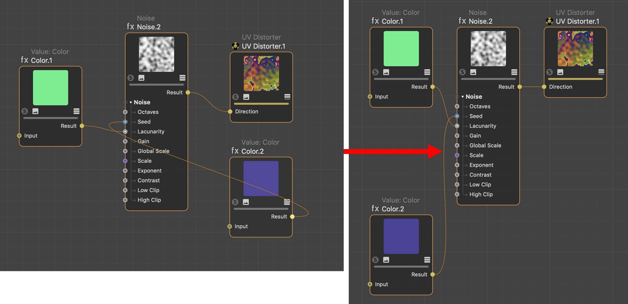
In the following example, only the Spiral Node’s Arms setting should be displayed as an externally controlled setting. Proceed as follows:
-
Place all Nodes in a group by selecting them and selecting Group Node from the context menu. Open the group (click on the Group Node’s arrow icon).
-
Right-click on the Spiral Node’s Arms port and select Propagate Port from the context menu.
-
Exit the group by clicking on Node in the Material or Group Name
- Select the Group Node and select Set as Start Node (Node menu)
As soon as you select the Node Material, only the Arm setting will be displayed (image bottom right).
If you now click on the Group Node to select it and select Convert to Asset , the Asset will be created.
The Clear Start Node command removes the Start Node state.
Opens the Material Editor for the material currently displayed in the Node Editor. In principle, the Material Editor has the same settings as the Attribute Manager for a selected material.
This command selects the corresponding Node Material in the Material Manager for the active Node Editor, whose material settings will then be displayed in the Attribute Manager.
Unused Nodes are Nodes without connections (groups are not included). They therefore serve no purpose and can be deleted using this command.
With this command, the selected Nodes, all ports without a connection will be hidden (these can be unhidden using the Add Input or Add Output commands).
View menu
If Nodes lie outside of the Node Editor view, these can be shown simultaneously using this command. The view will be scaled accordingly to ensure that all Nodes are displayed.
Shows all Nodes in the Node Editor view. The view will be scaled accordingly.
Selected Nodes will be displayed at the center of the view without changing the zoom factor. For multiple selections, the center of the selected Nodes will be placed at the view’s center.
All Nodes will be placed at the center of the view without changing the zoom factor.
Enlarges or reduces the Node Editor view. Using the 2 hotkey and the mouse works faster.
If you have a Node network made up of 376 Nodes, for example, you won’t see much detail in the Node Editor view. This command sets the zoom to a quite legible 100%.
Hides or shows the grid in the Node Editor view. Grid snapping works independently of this display.
Enables or disabled grid snapping. If enabled, Node edges will snap to the grid lines.
Shows or hides the Navigator.
Blenden Sie hiermit den Infobereich links unten ein und aus.
When working with groups you often have to delve into these, i.e., the Node Editor shows the contents of a given group. Call up this command if you want to move up a level, i.e., out of this group. Alternatively, you can click on a layer to which you want to jump next to the Node path.
Selected or all Nodes will be arranged so they are visible in the current view - compact, arranged in order and positioned horizontally/ vertically:
 Before and after the Arrange Selected Nodes command is called up.
All Nodes displayed in the Node Editor will ba arranged according to the previous description.
With this command you can create parameter input ports for all selected ports. See Input and Output Group Area for differences between input and output ports and propagated ports.
Asset menu
Details about Assets can be found under Assets.
Similar to Edit Asset, only that a selected asset instance must lie in the node view.
Assets are most often created from Group Nodes (an example process is described here).
As soon as this command is called up for a selected Node, a dialog window will open:
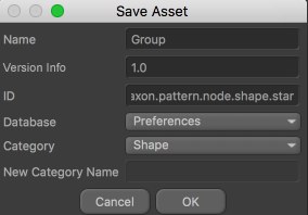
Name
Define a name for the Asset. This Asset will appear with this name in the Asset list. This name will also appear in the Info area if you use it in the Node Editor view as an instance (i.e., you drag it from the Asset list into the Node Editor view). Even if you rename the Node, this name will remain unchanged.
Version Info
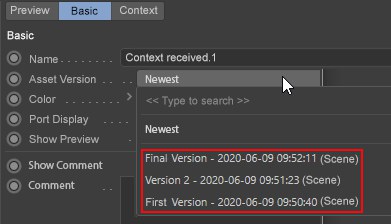
Assets can have several versions (versioning). Imagine you create an Asset, build a scene with it and save the scene. You then edit the Asset by, for example., changing a color or adding Nodes. If you now save the Asset (Save New Version) you can use the Version Tag to define a version (e.g., 1.1 or Version 2, etc.). The Asset will then contain both the original and the new version.
If you now load the originally saved scene or use the Asset anew, the newest Asset version will be used by default. You can, however, switch between versions in the Asset instance (i.e., the Group Node) at any time:
You can also imagine versioning as follows: Assuming you saved a primitive cube in Cinema 4D R15. A Fillet setting was added in R18. If you load the R15 scene into R18 you often had a compatibility mode that lets you load and older version. If the option is enabled, the cube is loaded without fillets, if disabled, with fillets. Sometimes the cube would be loaded without any prompt regarding its older state. If versioning were applied to primitives, you would be able to switch back-and-forth between versions.
MAXN can update the nodes it supplies in the application via the Online Updater. This is done in a manner that ensure that older scenes remain functional.
What you define here in the Version Info will subsequently appear in the Asset instance as the Asset version name.
ID
This is a unique ID (you don’t have to enter anything) is assigned with which an Asset can be clearly identified by the application. This ID - supplemented by a random set of characters - is then displayed in the Info area of the Node Editor when the respective Node is selected.
Database
Assets can be saved in different databases.
Most often, the following will be offered:
- Preferences: Assets will be saved in the default directory userrepository
- Scene: An Asset copy will be copied in the scene file (this also happens if the scene is saved using the Save Project Including Assets option).
- + Databases that are linked in the Preferences menu under Files/ Paths/ Databases. Note that Assets linked as ZIP files in databases cannot be saved in these)
This menu is dynamic and will display all corresponding locations.
Category
If you take a look at the Asset list you will see numerous Assets in the alphabetically arranged categories. You can add categories at any time (these are themselves Assets by the way).
The Asset to be saved will be placed in the selected category. Custom Assets can be dragged and dropped to other categories.
Clicking on OK will save the Asset and add it to the Asset list and will make it visible in the Node Commander where it can be used.
Asset Nodes, which are mostly created from groups, can be converted back to Groups using this command. The arrow icon will then be displayed again.
Opens the group (or double-click on the Node).
If an asset is encrypted, this command will be grayed out.
When editing existing Assets, modifications made should be saved using this command. A dialog window will open that you should be familiar with from the Save Asset command (see above). Since the old Asset state is also saved, versioning will be implemented.
When editing existing Assets, a new Asset can be saved without the aforementioned versioning. A dialog window will open that you should be familiar with from the Save Asset command (see above).
Mode Menu
The Node Editor has various modes that will normally switch automatically- depending on which Node type is being used. If the Scene Manager is activated, for example, the Scene mode will be activated; if a Node Material is activated, the Node Editor will switch to Material mode.
You can also switch manually if you want. You then might have to select the fitting element (e.g., a Node Material).