Node Editor
![]()
![]()
The Node Editor has different modes, depending on which Node type is used. For example, if you enable the Scene Manager, the Scene mode (see also Scene Nodes Introduction) will be used; if you enable a Node Material, the Material mode will be used. In the following you will find references to the fact that a particular function will only work in a particular mode.
General
 Material mode.
The following applies to the Node Editor (Material mode):
The Node Editor is where everything takes place when creating and editing Material Nodes (in the following referred to as Nodes). Everything you see in the Node Editor has to be linked with a Node Material (please note this tip), i.e., to create and edit Nodes, a Node Material must be selected. The Node Editor always displays the currently selected Node Material.
Please note that Nodes are quite complex and to use them effectively you need to have a higher level of knowledge about how shading and rendering works in general. However, several functions are very simple when a pre-defined material is used such as the Uber Material, which is almost as easy to use as a normal material (and can still be used in conjunction with an image node in various material channels)._
The general flow of data is always from left to right. At the far right, everything must always culminate in a Material Node (no Material Node means no working material; only 1 Material Node per material).
The Node Editor can be opened as follows:
- Double-clicking on the Node Material
- Clicking on a Node Material’s Node Editor button (Basic tab)
The following applies to the Scene Node Editor:
The Node Edtor’s content is not assigned to a specific element (such as the Material Node Editor to a Node Material) but is itself displayed in the scene. Therefore, the last output Node must always be connected to the scene output via its Op Output output, otherwise no geometry will be generated.
Note that the Scene Node Editor is designed for advanced users and a higher 3D skillset and technical knowledge is needed. See Szenen Nodes Introduction for a brief introduction.
The Scene Node Editor is opened via the Scene Node Editor command in the main menu (Window / Scene Node Editor).
The Editor also offers several special functions that are described farther down.
As with the Node Materials when they were introduced, the Scene Editor comes with a range of additional Nodes for specific uses. Many Nodes (such as the Math Node) work in both the Material Node Editor as in the Scene Node Editor. A description of most Nodes can be found under Individual Assets. The new Scene Nodes can primarily be found in the categories Geometry, Array, Effectors, Fields, Flow Control, Operators and Distribution.
Several special Viewport settings for displaying geometry generated by the Scene Node Editor are available in the Project Preferences menu (see Nodes).
Node Editor
Navigation:
As with other Managers; the following hotkeys can be used to navigate in the Node Editor (see also commands in the View menu):
-
Move: Press one of the following keys and drag the mouse: MMB, 1 + LMB, Alt + MMB or click and drag in the Navigator. If Touchscreen is enabled in the Preferences menu (Input Devices menu), the following will also be enabled:
Mouse wheel up/down (move vertically) and Shift + mouse wheel (move horizontally) - Zoom: Press one of the following buttons and drag the mouse: Alt + RMB, 2 + LMB, mouse wheel (if Touchscreen is enabled: Ctrl + mouse wheel)
- Show all or selected: H or S.
Creating Nodes
Nodes can, for example, be created in the following ways.
- Drag a Node from the Asset list into the empty Node Editor (new Node without connections), onto the input port of an existing Node (ports will be connected directly) or onto a connection (only works with fitting Nodes - these will then be added to the connection). Alternatively you can open the Nodes Commander by pressing the c key on your keyboard. For both methods the following applies: if you drag a Node onto an input port and release the mouse button, a small menu will open if multiple output ports are possible where you can select the output port of the first Node to be connected.
-
In the Node Editor’s Attribute Manager you will find a connector icon for just about every input type:
. One click will open the context menu. Selecting Connect Node will display a list of all Nodes. When you select a Node, the Node will be created and simultaneously connected with the input. The same can be done by right-clicking on an input port.

- Bitmaps should also be mentioned at this point. If you drag a bitmap file from outside of Cinema 4D directly onto the Node Editor view (or even onto ports!), Image Nodes with a correspondingly linked bitmap will be created.
Note that not all output ports can be connected with all input ports. Many file types will be converted automatically but there are limits to this (e.g., a ShadingContext cannot be connected with a BooleDatatype in the Material Node Editor). Cinema 4D will show you if a connection is possible: if you hover over the port to which you want to connect, the potential connection will be either bright (possible) or dark (not possible).
Moving Nodes
Nodes can be moved at any time by clicking and dragging them. Multiple selections will be moved as a whole. If you move your selection to the edge of the Node Editor view, the view will start to scroll correspondingly.
Connecting Nodes
Node can be created in the following ways (drag & drop, double-click, etc.):
- Basically in the Asset Browser
- Drag a Node from the Asset Browser into the Node Editor
- Click on the Add Node button or
- double-click on an empty area of the Node Editor (alternatively: c key), which will in turn open the Asset Browser’s Asset List.
In order to let data flow from one Node to another they must be connected: For this, Node outputs (right Node side) of one Node can be connected with the inputs of another Node (left Node side). To do so:
- click once on the output port and once on the input port (or vice-versa). This is very practical for Nodes that lie far apart from one another.
- click and drag from the first port to the second and release the mouse button.
- In both cases you can "drop" the connection end onto the middle of the Node: a list with all input and output ports will be displayed from which you can make a selection (if you drop the connection onto an empty area, input/output ports for groups can be drawn out).
The following applies:
- As long as you’re in connecting mode (clicked on the first port to be connected), the mode can be disabled by pressing Esc on your keyboard
- Existing connections can be "re-routed" at the port or the connection itself by Shift+clicking on other ports (even other Nodes).
Selecting Nodes
Nodes can be selected dragging a rectangle around them (simply click on an empty area of the Node Editor view and drag) or by clicking on them. As always, the Shift and Ctrl/Cmd keys cam be used in conjunction with making selections. In the Edit menu you will find several additional selection commands (such as Select Connected). The selected Nodes’ settings are displayed in the Attribute Manager.
Deleting Nodes
Selected Nodes can be deleted by pressing the Backspace- and Del- keys.
Node Editor Title

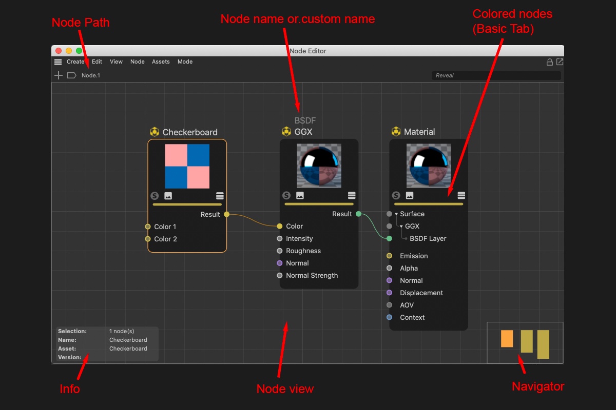
At the very top of the Node Editor you will find the following elements (from left to right):
- Add Nodes: Opens the Asset Browser’s asset list.
- Scene Nodes: Nodes of any type can be grouped and additional groups can be created within this group. If you open these groups, their respective hierarchies will be displayed. Clicking on a group higher up in the hierarchy will let you jump to that group. The Edit Asset mode will also be displayed here, which can be exited by closing the opened Node Editor.
- Highlight: Enter a series of characters here that affects the Nodes displayed. Nodes whose names contain this series of characters will be displayed more prominently by fading all other Nodes. This can help when looking for specific Nodes among a myriad of Nodes.
Navigator
The Navigator is located at the bottom right of the Node Editor view - it’s a small depiction of the entire Node constellation and serves for better orientation and quicker navigation, especially for complex Node setups. The light gray triangle shows the visible part of the Node Editor view. You can move this section by clicking and dragging in the view.
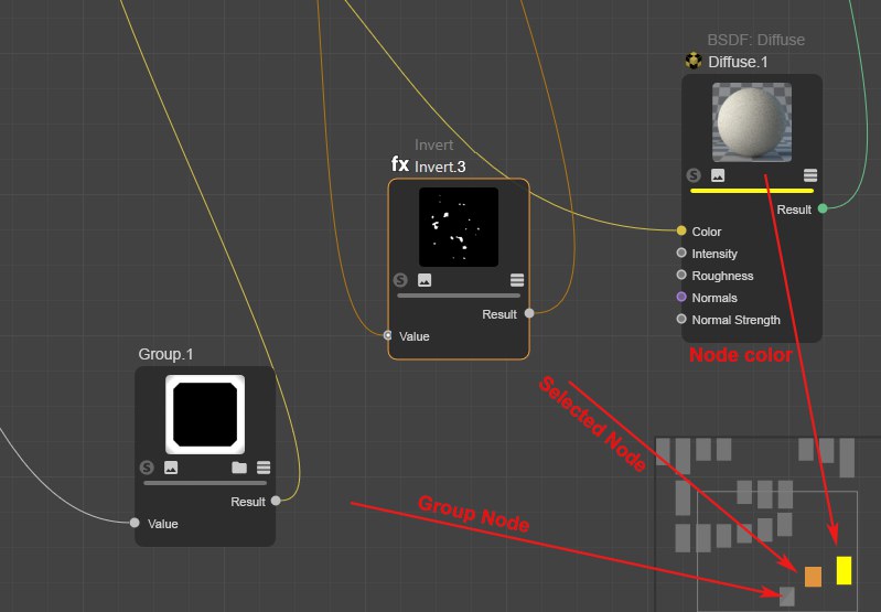
The following Nodes have a special display:
- Colored Nodes (Basic tab) will be displayed with the identical color
- Selected Nodes are also selected
- Group Nodes will be displayed with a diagonal element
Input and Output Group Areas
On each side of the Node you will see a dark edge (if output ports were already created). Connections/ports can be output with these areas by dropping a new connection into an empty region of the area. This makes little sense for individual Nodes but if you combine different groups with one another, you can use this method to create a port that is shown as a group port (as in the image below). This means that even in a group within a group a specific Node port at the very bottom can be connected from the outside (or as an output to the outside).
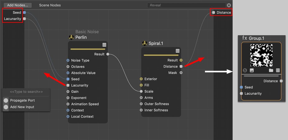 Node ports in groups can be led outside.
When a connection is released in an empty area, a small menu will open (see image bottom left) with the following options:
- Add New Input, round port: Here, the connection can be deleted without deleting the input. An input can be re-connected from the inside.
- Propagate Port, square port: If you remove the connection here, the port will also be deleted. Ports also pass on their properties to the outside, which, however, is currently barely used.
- Node List: Here you can select the Node whose input you want to connect with the current Input port.
Parts of the described functionality (creating inputs) can also be done via the port context menu commands.
General information about Nodes
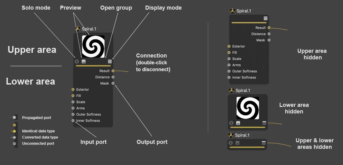 A Node setup and display example (it’s also possible to only display connected ports).
The core component of the Node System is - logically - the Node. A Node has inputs into which data from other Nodes is entered, which is then processed by the Node and the result is passed to its outputs. Inputs and outputs have ports through which the connection to other Nodes can be made. Basically, an input port can only have a single connection and output can have any number of connections.
Nodes can be grabbed on the left or right edge and made wider or narrower.
A Node has an upper area and a lower area:
Upper area
The Node’s name is displayed over the respective Node. If you rename the Node in the Basic tab, its new name as well as the original name will be displayed. The latter so you always know which type of Node you’re working with. This is also the name used in the Help. The name in white text can also be modified by double-clicking on it.
The upper Node area contains the Node preview - for Nodes wherever it makes sense. If the settings of the connected input Nodes change, the preview will change accordingly. You can show or hide the preview using the small icon (2nd from the left) (a command can also be used - see above).
In the Preview you will find the Solo Mode option on the left (see Solo) if the Node Preview is supported, which is, for example, not the case for Nodes for the Scene Node. Next to it on the right is the Preview icon.
You can click on the third icon (only visible for Group Nodes) to display the group content in the Node View (double-clicking on the Node will do the same).
The Display Mode icon at the far right can be used to switch between port display modes, as can be done using the three port commands machen.
Below the row of icons you will see a color bar whose color is defined using the Color setting in the Basic tab. This can make it easier to find certain Nodes. By default, some Bode types are already colored but can be recolored at any time.
Lower area
The lower area contains the input ports on the left with their respective names and the output ports on the right with their respective names. Ports can be hidden, and their order can be changed by moving them. Note that not all input ports will necessarily be listed in the Node itself. These can be displayed using the context menu.
Certain Nodes (such as the Layer Node, for example) even have drop-down port groups for each layer.
Depending on the data type being processed, ports will be assigned a certain color (see next data types).
Ports can be selected (using the Shift or Ctrl/Cmd keys to add or remove selections) so they can be affected by certain commands (see Node menu or context menu).
Data types and colors
Inputs and outputs are colored accordingly. Fitting data types for input and outputs will be displayed using colors. The most important types are:
- Dark gray: Represents a container consisting of various data types, as would be the case when transmitting complex settings for shading for a given material or as it appears with an Op Output port.
- Light gray: Represents numeric values. This can be whole numbers (integers), percentages or a number with a comma value (float).
- Yellow: Used for color values (RGB vectors) or textures
- Blue: Used for transferring data types such as Matrix, Text, Boole, Array .
- Violet: These are ports that work with vectors, for example, in conjunction with Normals and for the displacement of a material or if an object’s position should be ascertained.
- Green: Reserved for BSDF layers for Material Nodes, which can be used to define physical shading and reflectance information.
As in XPresso, atypical input and outputs can be connected with one another. As a rule, a constructive conversion of the data types will take place. For example, a texture can also be connected to an input for a float comma value. The texture’s RGB values will then automatically be converted to brightness values. Using this method, color textures can also be used to, for example, control the Roughness of a BSDF layer. This type of conversion of data types is denoted at the receiving Node by an additional point at the respective input.
Context menu
If you right-click on a Node/port, a comprehensive context menu will open, which contains commands mostly from the Node Editor menu. These are described here, except for the following:
Not all inputs listed in the Attribute Manager have to be displayed by the Node as a port. Sometimes only the most important are shown. Use the Add Port command to show all hidden ports. If one is selected, it will be displayed again (if All is selected, all input ports will be made visible).
This menu point is not available if all input ports are displayed.
Normally, all outputs are displayed. If not, (e.g., if Remove Unused Ports was applied) these can be displayed by selecting one of the output ports from the list.
Propagate Port
A list will be displayed from which a Node to which you can link can be selected. If multiple output ports come into question per Node, click on the small black arrow and the output ports that can be selected will be displayed. In addition to the complete Asset list, the first entries will be existing Nodes where Nodes are listed that are contained in the current Node Editor view. There is also the Add Group Input option with which a port can be drawn from a group (see also Input and Output Group Areas).
Note that this list is created dynamically, and only fitting Nodes will be suggested.
Replace Node
For the current, connected input port, the "feeding" Node will be replaced by one from the list. Note that the complete Node chain will be deleted at the Node to be deleted. This only applies to the Nodes being fed: Nodes that are connected to other output ports remain unaffected.
Textures
All loaded textures are listed here. Select a texture from the list to feed it into the input port.
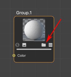
Load Texture
Selecting this option will open a context window from which you can select a bitmap or video, which will then be fed to the input port using an Image Node.
Remove Port Instance
Several Nodes such as the Layer Node or the Gradient make this command available. With it you can delete elements such as Layers or Knots.
Selecting this command will hide the selected ports. This only works with ports that are not connected. The hidden port will then appear in the previously described list under Add Input (and can be made visible there).
Note also the Show All Ports command and the next two commands described there. This is a different functionality from the hiding or displaying of ports.
 The Port Inspector can display the values of simple data types.
Details about these two Debugging tools can be found there.
Most settings have a default value, which is defined when the Node is created. Using this command, modified values will be reset to their default values. This only affects Nodes that are not connected.
Propagate Port
Calling up this command (only of use when the Node Editor view shows a group’s contents) creates a connection to the outside or to the parent hierarchy. See also Input and Output Group Areas.
Here you can copy values/types of individual ports to the cache (for a port with an integer value of 4 it would, for example, look like this: int64:4). These values/types can be pasted to other selected ports using the Paste Value command. The data types will be converted, if possible.
A data type can be copied using this command (fora port with an inter value of 4 it would, for example, look like this: int64). Since it’s possible to create very complex data types (e.g., with a Switch Node) you can use this command to save time by simply copying the data type and paste it at the desired location. For example, for a Compose Container Node, for which you can also define data types, click on the button at the far right of Data Type and select Edit Data Type and paste the data type there.
A Solo functionality can be enabled for Nodes. If this Node has multiple outputs, one of them must be defined as a Solo Port, which is what this option does.
In the upper area of a Node you will find the Node’s preview. If a Node has multiple outputs, this option can be used to define which output should be displayed in the preview.
Connections
Proceed as follows to connect a Node port with another port:
Connections can also be selected, whereby you can almost always do so in conjunction with the Shift and Ctrl/Cmd keys to add or remove selections (clicking and dragging a box can also be used to make a selection). So what can be done with selected connections? They can, for example, be deleted or modified per context menu commands described below (only those commands not described elsewhere are described below).
Add Converter
If ports are already connected, this command can be called up. It places a Converter Node in the connection, i.e., its input and output are already properly connected.
Deletes selected connection.
Muted connections will be displayed with a dashed line. Values will not be accepted from the previously connected Node but from the Attribute Manager instead. This lets you temporarily disable connections for test purposes, for example.
Other Node Editor components
The icons at the top right

At the top right of the Node Editor you will find the following 5 icons, from left to right:
- Here you can, for example, activate or deactivate the automatic layout. This is useful when working in the Scene Manager where Nodes are created. If this option is disabled, all newly created Nodes will lie on top of one another; if activated, the Nodes will be re-arranged and positioned in a readable format.
- Lock Node view: Normally, the Node view will show the Node Material currently selected in the Material Manager. If the view should not change, this option can be enabled to prevent this from happening.
- New Node Manager: This will open a new Node Editor. This can, for example, be helpful if you have a Node network made up of hundreds of Nodes and want to work in several areas simultaneously. Or you want to make the Nodes of two Node Materials visible at the same time (see also previous icon).
Connectors
The most major change compared to the previous Attribute Manager are the linked fields that have been replaced by Connectors. Node inputs can either be fed with values by simply entering values for given settings or - and this is new - by connecting Node inputs with node outputs of other Nodes, i.e., make a connection (which is what Nodes are all about).
Click on the icon at the right of the setting name (the "connector") and select a Node from the Connect Node list to connect with the input that you select (you can, of course, simply connect ports in the Node Editor view). The selected Node will be created and linked:
Bitmaps can at any time be dragged from outside of Cinema 4D onto a complete parameter line *incl. parameter name, connecting icon and GUI element) to link a given setting using an Image Node.
As soon as a parameter is connected with another Node, the following applies:
- A small arrow will appear instead of the animation icon. Click on this arrow to display the settings of the docked Node.
- The setting can no longer animate these using the usual animation icon - this will then be displayed (of course you can animate the setting of the connected Node as usual). A setting cannot be controlled simultaneously by the Timeline and another Node.
The connector icon can have one of the following 3 states:
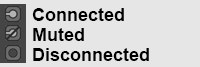
- Connected: The values flow from the linked Node to the Node input. On the right next to the Connector, the linked Node’s name will be displayed. You can click on this name to select the corresponding Node and display its settings.
- Muted: A connection to another Node exists, whose values will, however, not be assumed (instead, the values defined in the Attribute Manager will be used).
- Disconnected: The values defined in the Attribute Manager will be used.
Clicking on a connector icon will make the following commands available, from which most should already be familiar from the port context menu. The connector icon makes a similar functionality available, which makes it possible to access a port in the Node Editor per right-click.
In the following, only the Connector’s commands are described.
Add Layer
This command can, for example, be found in the Layer Node. The selected Node will be linked with a new layer.
Copy
Copies the connected output port to the cache.
Paste (Link)
The cached output port can then be linked with a different input port. This way, multiple inputs can be connected with the same output port.
Paste (Duplicate)
This command connects the output port in the cache with the input on which you click. Contrary to the previously described command, a duplicate of the entire feeding Node is created.
Remove
Removes the connection from the input port.
Mute Port
The connection is maintained but no data will be passed. Instead, the value defined in the Attribute Manager will be used for the input. Call up the command again to allow data to be passed again.
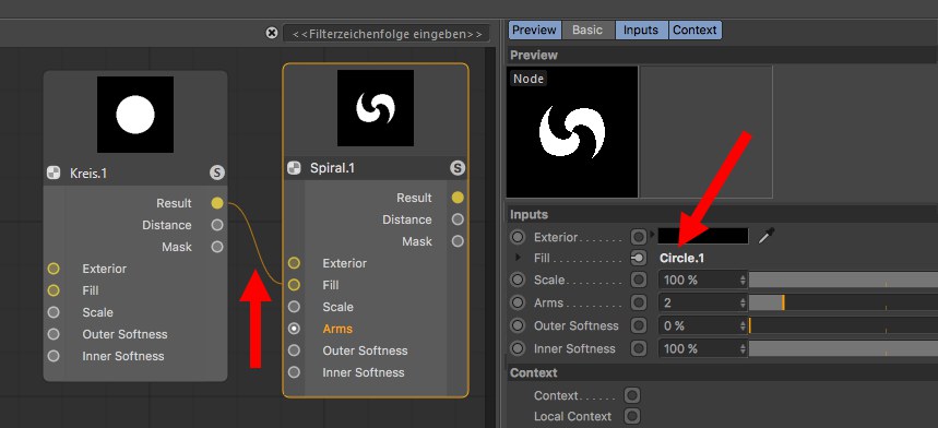
Show Subchannels
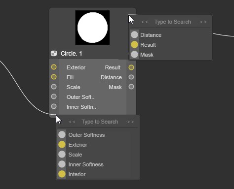
Several Nodes such as the Layer Node or Grading Node offer this mode. Enable this mode, for example, to display the layer settings as animatable or adjustable settings. In addition, the input settings of the feeding Node can be displayed by activating one of the layers. In the following example, the inputs would be those of the Circle Node.
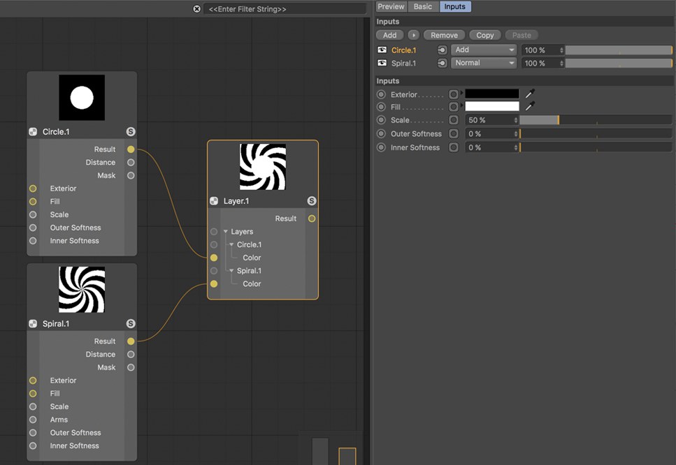
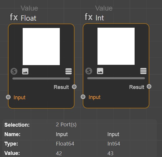 Multiple port selections are also possible in order to compare values.
Info area
At the bottom left you will find the Info area in which you will find information pertaining to Nodes, connections and ports.
For Nodes:
- Selection: The number and type of selected elements
- Name: The Node name as it is defined in the Basic tab
- Asset: The non-modifiable Asset name as it is defined internally. Why do the Asset and Name infos differ? You can change the Name at any time which will differ from that in the Help. Since Cinema 4D R23, however, both names will be displayed on the Node.
- Version: When you create Assets, a version number can be defined, which is then displayed here, including date and time. This way you always know which Asset version you are currently using.
- ID: A unique ID, which has no additional informational value for you.
- Errors: Here all errors will be displayed (e.g., if an automatic conversion of a data type failed)
Additional information for connections:
- Selection: The number of selected connections
- Port Type: The data type that the port expects as input or itself puts out
- Connected Type: The data type that flows through the connection
Additional information for ports:
- Port Value: If a port has no connection, the value defined in the Attribute Manager will be displayed
Opens the group (or double-click on the Node).
If an asset is encrypted, this command will be grayed out.
When editing existing Assets, modifications made should be saved using this command. A dialog window will open that you should be familiar with from the Save Asset command (see above). Since the old Asset state is also saved, versioning will be implemented.
When editing existing Assets, a new Asset can be saved without the aforementioned versioning. A dialog window will open that you should be familiar with from the Save Asset command (see above).
Material Node example scene
The following material was created using Nodes only. Not bitmap or texture was used!
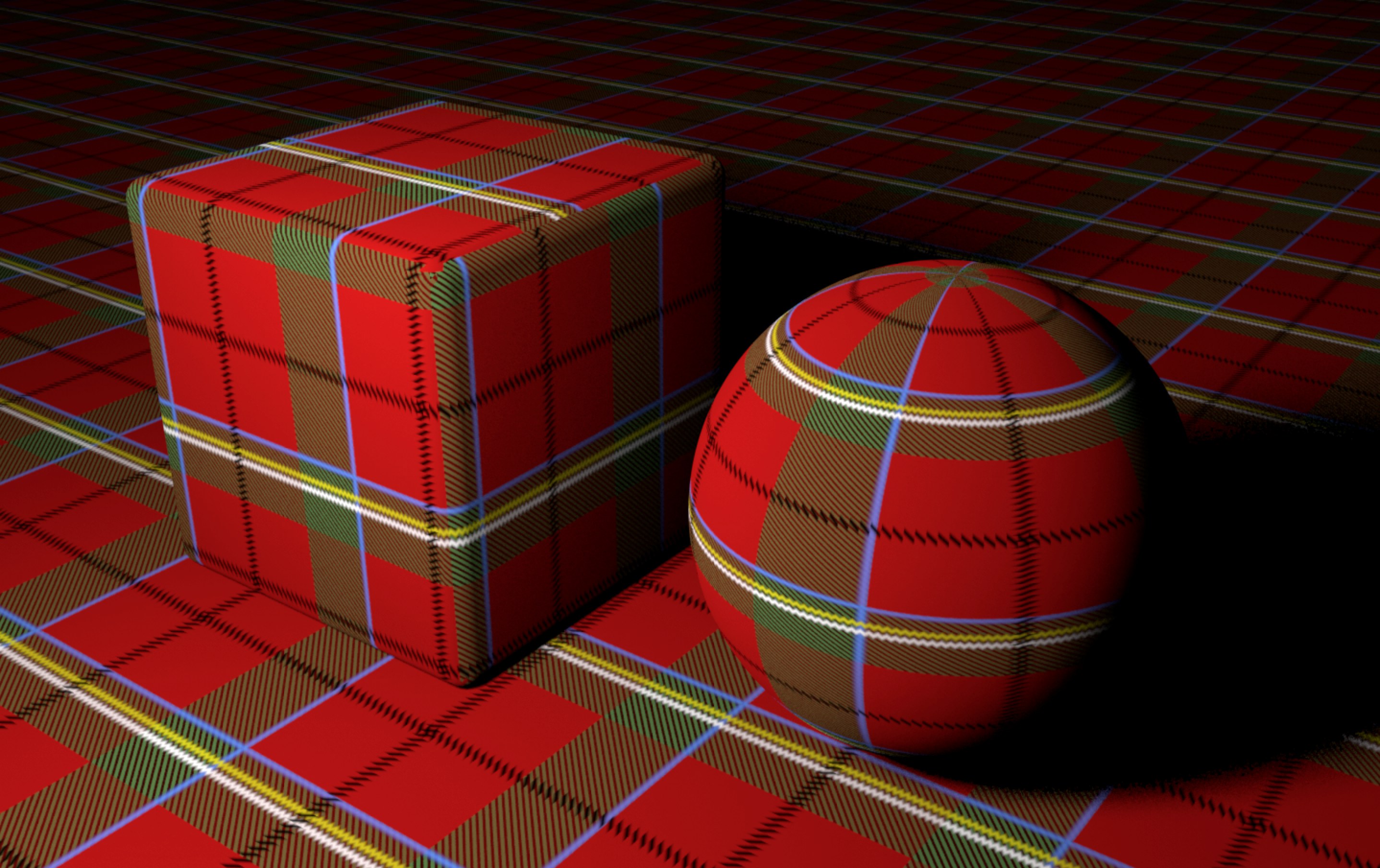
Load the following scene:
Here you can get an idea of what is possible using Nodes. Right-click on the material and select Node Editor to see what the Node setup looks like. Note the Plaid Group Node in which additional Node networks are nested.
Special informaiton about the Scene Node Editor
Aside from the descriptions above, the Scene Node Editor has several special features:
-
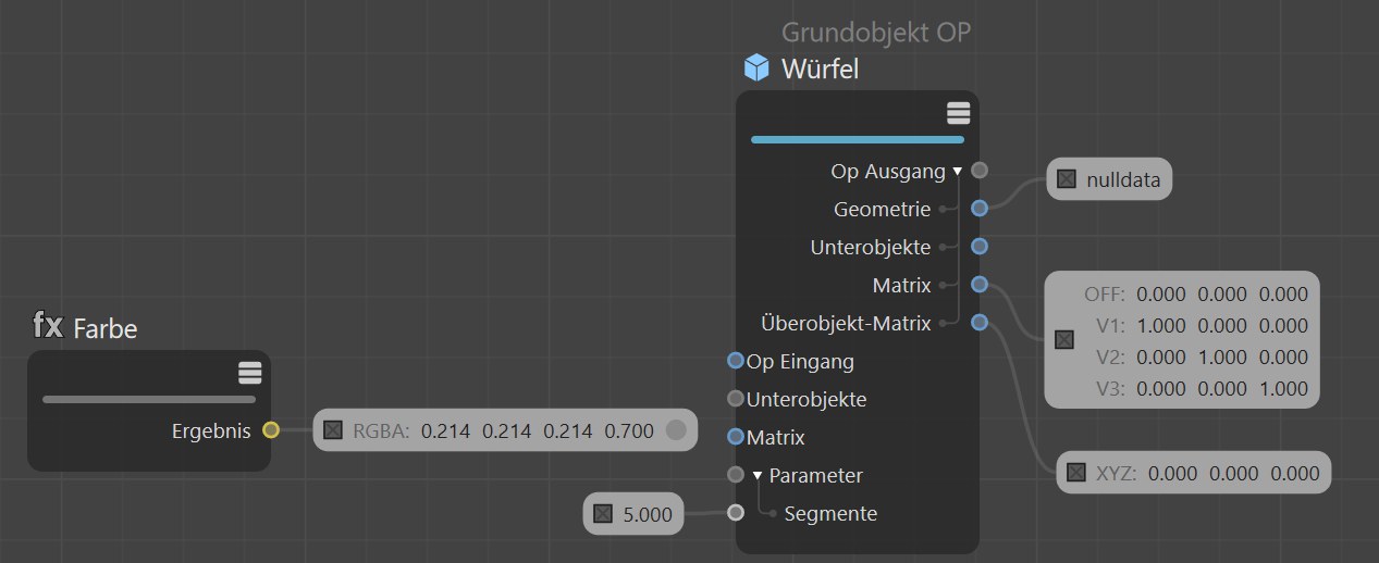
The Op Output connection for severyl Nodes in the Scene Node Editor is displayed in bold:
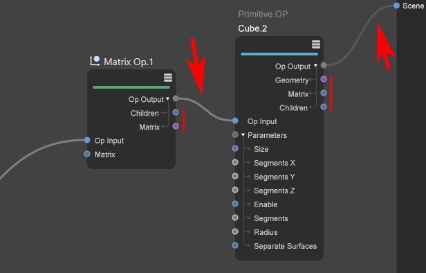
These connections are a conglomerate of different values.
Click on the small arrow at the Op Output port to open them and display the value type. To create geometrty that is visible in the scene, a Op Output port must always be connected with the Scene port.
- Nodes in the Scene Node Editor often have not preview
- Nodes in the Scene Node Editor have no Solo Mode