Object Properties
 The path of a cube (top) and a circular plane (bottom) are being traced using the Tracer.
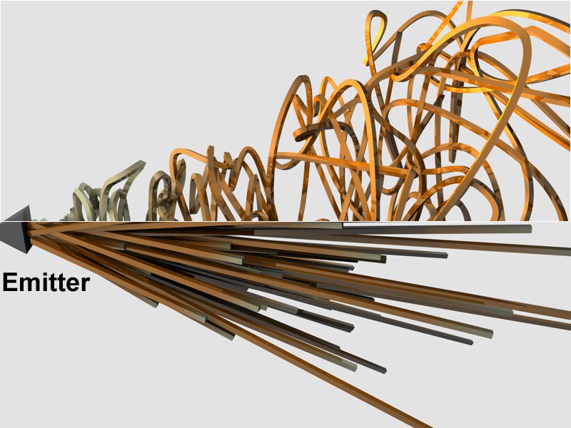
Drag the object(s) to be traced (polygonal objects or splines) from the Object Manager into this field. To trace particles, drag either the emitter (Cinema 4D) or the particle group (Thinking Particles settings) into this field.
The Tracer can even be applied to PLA and Pose Mixer animations …
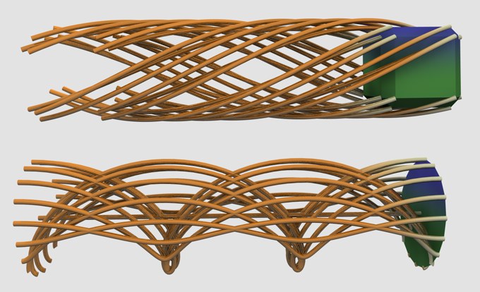
 At top: Connect All Objects. At bottom: Trace Paths. Both using one Particle Emitter.
Trace Paths: Paths of object vertices or particles will be made to splines.
Objects or particles will be connected with a segment by a common spline.
For example, this lets Splines be created using Null Objects:
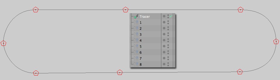
The Spline pictured above could, for example, be transformed into a pearl chain using a Cloner Object. This allows better control of the Null Objects when subsequently animated as opposed to using PLA Spline animation.
Interesting effects can be achieved when cloned objects (here spheres) are used:
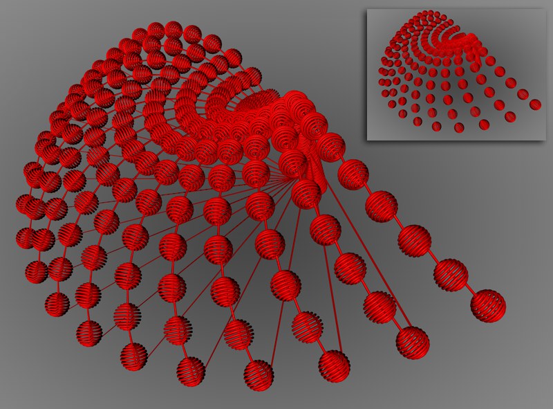 A cloned Sphere in Connect All Objects mode and Connect All Elements mode, respectively (top right).
Objects or particles (object vertices can also be connected, depending on the type of traced object or the Handle Cloners modes) from different objects traced by the same Tracer will be connected by a common spline but connected by different segments.
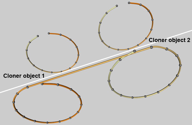 Two clones have been placed into the same Tracer (the Tracer lies in a Sweep object). At top: Connect All Elements. At bottom: Connect All Objects.
Use this setting to define at which frame interval (in an animation) in internal spline vertices should be set. 1= one spline vertex each frame.
Use this setting to temporarily turn the Tracer off. This will result in gaps in the splines, thus creating spline segments.
When tracing splines or polygonal objects, use this setting to define whether all object or spline vertices should be traced (active) or only the object’s center (not active).
Particles can be placed into groups as desired when using Thinking Particles. Use this setting to define whether child objects of the particles groups in the Trace Link field should also be included.
If several Cloners are nested in each other, the Tracer must know how to handle these objects. The following options are available:
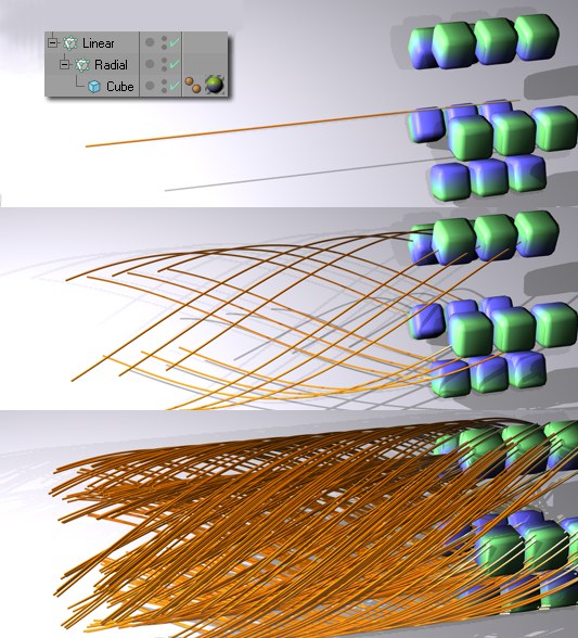 From left to right: Nodes Only; Immediate Clones; Clones from Clones. Trace Vertices active. Insert: Object hierarchy. The Tracer follows the Cloner, which moves from left to right.
Only the Cloner that has been placed in the Trace Link field will be used. This Cloner’s child objects will be ignored.
Any child objects of the object located in the Tracer Link field that are also clones will be included.
All clones will be included that are child objects of the Cloner located in the Tracer Link field.
This setting should be activated if the Cloner (not the clones!) should be included as a spline when the splines are generated internally. In most cases, though, this will not be necessary.
You can position the Tracer and the object to be traced at any location. The following two options are available:
This will basically pull the rug out from under the splines, i.e., when the Tracer Object is moved, the spline tracings will be strongly affected. The object to be traced does not have to be moved - this would move the surrounding space itself.
The traced splines will be positioned relative to the Tracer Object. Only if the Tracer’s position is set to 0,0,0 will the spline tracings match the traced object exactly. Otherwise the tracings will appear at a distance equal to the Tracer Object’s distance from the world coordinates. What this basically means: In certain situations, an emitter that has been traced and placed into a Loft object can be controlled more easily.
 These effects were achieved by using different Limit modes.
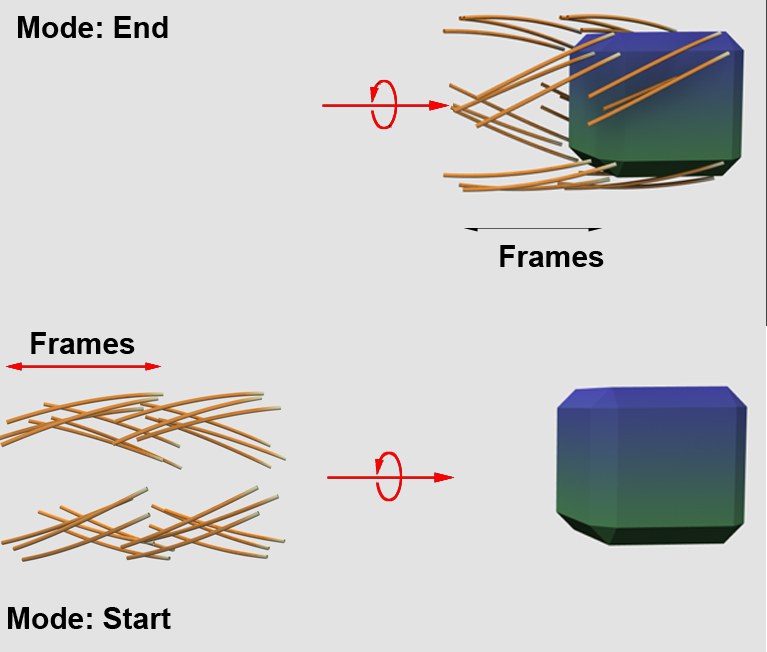
The spline length can be limited in the following ways:
No limit will be set. All movements will be made to splines.
Splines will be generated from the very beginning of an animation up to the number of frames defined by the Amount setting to the right.
The moving object or particle will drag a trail behind it. The length of this trail is defined by the number of frames set in the Amount setting to the right.
This simplest of all the spline types connects the vertices, which define the polygon, with straight, directly connected lines. You can use these splines to create angular objects or to simulate sharp jerky movements for animation.
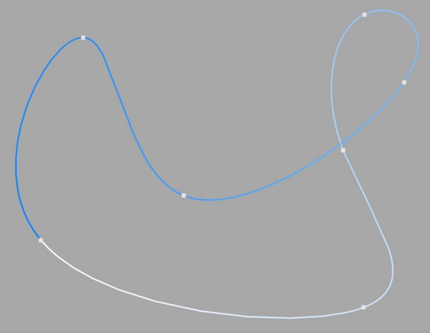
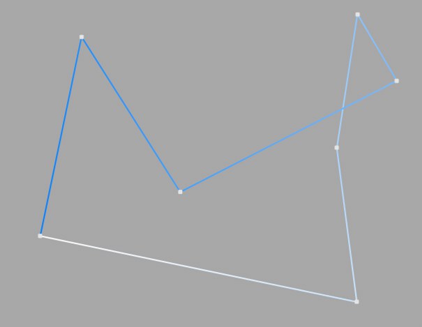
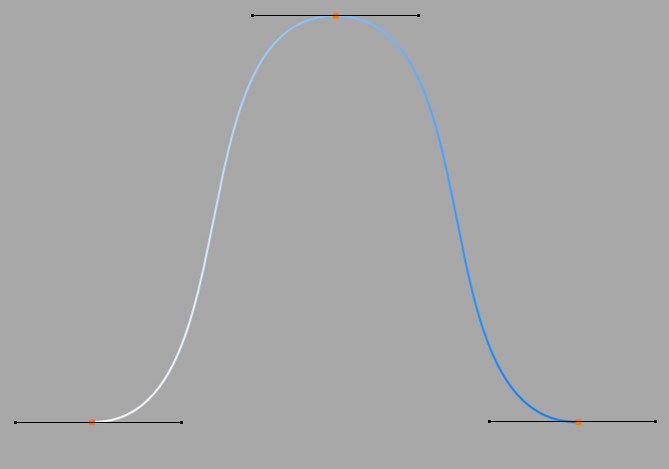
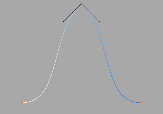
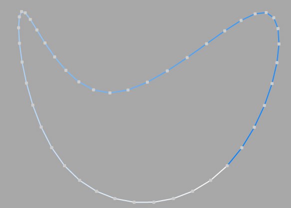
This kind of spline has a soft curve between vertices. The interpolated curve passes directly through the vertices. Looking at the two points at the top right of the diagram, you can see that the curve bulges more than is probably required. This behavior is called overshooting, and it often appears with closed curvatures. This becomes clearer when you compare this section of the curve with the same section of the curve with Akima interpolation.
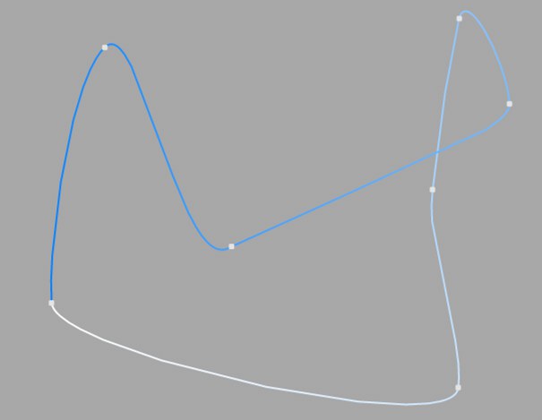
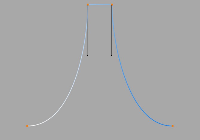
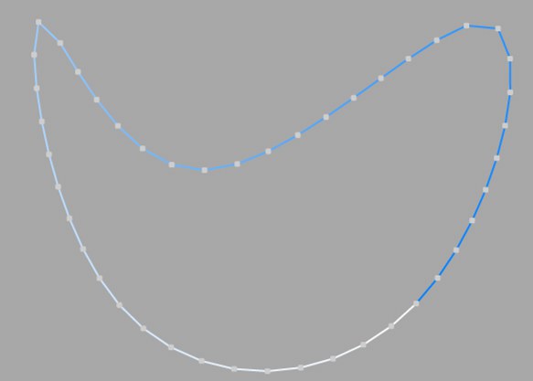
This spline type creates a soft curve between vertices. The interpolated curve always passes directly through the vertices. Overshooting does not happen with this type of curve. Akima interpolation adheres very closely to the path of the curve directly between the vertices but, because of this, it can sometimes appear somewhat hard. If this is not required, you should use Cubic interpolation.
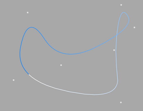
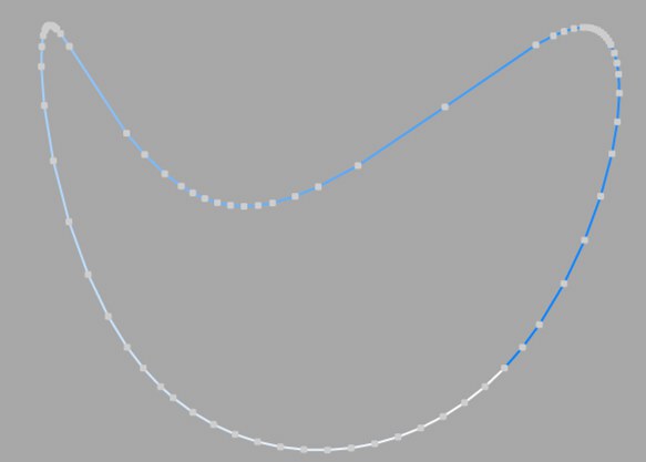
This kind of spline also creates a soft curve between the vertices. However, the curve does not pass directly through the vertices. This produces a very smooth curve. The vertices control only the approximate path of the curve. Distant points have less influence on the curve than those lying closer together.
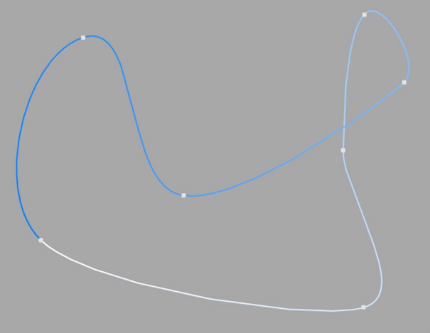
This spline type creates a soft curve path between the vertices, which can be controlled very precisely. The interpolated curve always passes through the vertices. Overshoot does not happen.
Compared to the other spline types available, Bezier splines are the most functional, offering the most control. Therefore CINEMA 4D uses Bezier splines for its animation system.
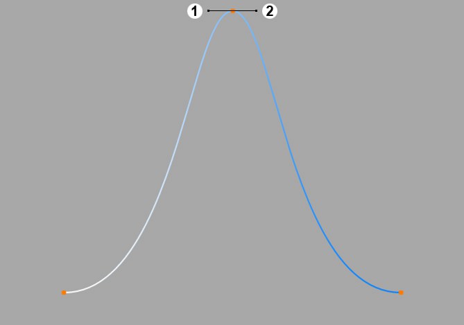
If you activate a vertex of the spline (i.e. by clicking on it), additional control points at the tangents to the curve become visible. Changing the direction of the tangent handles controls the direction of the curve at each vertex. To do this, drag the tangent end point.
By adjusting the length of these tangent handles, you can control the strength of the curvature. Drag the tangent end point towards the vertex point and observe the symmetrical movement of the opposite handle.
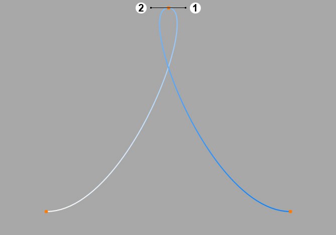
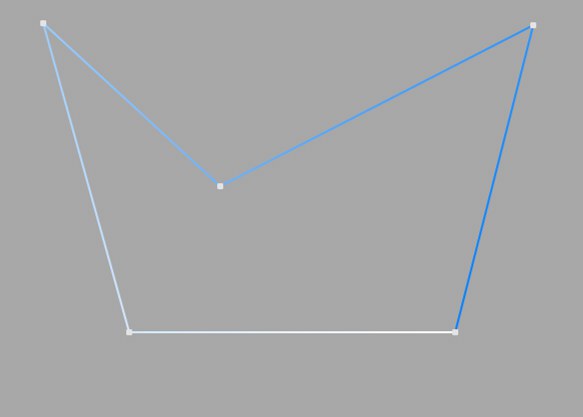
In the previous illustrations all tangents lie horizontally. Now let’s rotate the tangent of the upper point through 180° so that the left tangent end point lies on the right, the right on the left.
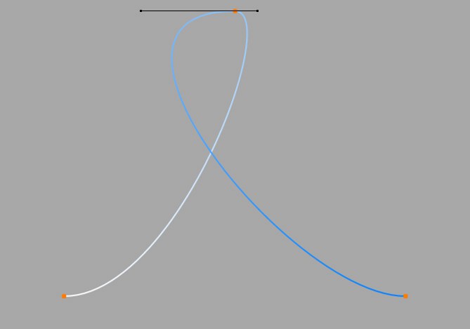
You can see the result in this illustration.
You can change the lengths of the tangents separately from each other. To do this, Shift-drag a tangent end point.
You can set different tangent directions on the right and on the left of the vertex. With this approach you can make the otherwise smooth path of a curve produce sharp corners and peaks, if required. To do this, Shift-drag a tangent end point.
If the tangents of two neighboring points have zero length, the segment that runs between the vertices will be linear. Thus, you can mix linear segments with curved spline shapes.
If you double-click on a Bezier vertex with the Move, Scale or Rotate tool active, a dialog opens that allows you to accurately enter both the position of the vertex (in the spline’s object coordinates) and the position of the tangent end points (relative to the vertex) numerically.
If you convert a Bezier spline to a different type of spline, all tangent settings will be lost. If a spline is converted from a non-Bezier type to a Bezier type, all tangents will be assigned default positions and orientations.
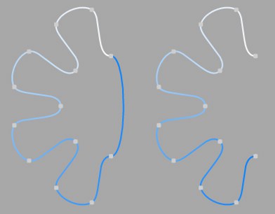 Close Spline enabled (left) and disabled (right).
Each spline segment can be closed or open. If a spline is closed, the start and end points are connected.
There is a big difference between closing a spline (and interconnecting the start and end points) and simply positioning the start and end points together. In the first case, the transition from the start to the end point is soft, in the second case it is abrupt.
To close the spline, Ctrl-click the start point.
Here you can define how the spline is further subdivided with intermediate points. This affects the number of subdivisions created when using the spline with Generator objects. Even after you select the Interpolation type from the menu for the Intermediate Points, you can still make changes.
This method of interpolation locates points only at the vertices of a spline, using no additional intermediate points. You cannot enter values into the Number or Angle boxes. For B-splines, the vertices, and therefore points, might not be located on the spline curve.
This interpolation type first locates points at spline vertices. In the case of B-splines, points are located at positions on the spline curve closest to the spline vertices. Number (N) corresponds to the number of intermediate points between vertices. The points are positioned closer together on areas of the spline with more curvature.
You cannot enter values into the Angle box. The interpolation is not affected by reversing the point order.
This interpolation subdivides the spline so that the distance between any two consecutive points, as measured along the spline curvature, is constant. One point is always located at the beginning vertex. For open splines, a point is also located at the ending vertex. Other points generally do not coincide with vertices.
You cannot enter values into the Angle box. The interpolation is not affected by reversing the point order.
Open spline: ((Number + 1) * (number of vertices - 1)) + 1
Closed spline: (Number +1) * number of vertices
So an open spline with four vertices and a number of 2 will contain ((2+1)*(4-1))+1=10 intermediate points. If the spline is then closed, a further (virtual) vertex is added — the number of intermediate points will then be (2+1)*4=12. This ensures that a spline is not more roughly divided when you close it.
This interpolation type sets intermediate points whenever the angle deviation of the curve is larger than the value given in Angle. The points of the resulting curve pass through the vertices. If a spline has several segments, then the value of Angle will apply to each segment.
The Adaptive method gives the best results in rendering, hence it is the default interpolation method.
You cannot enter values into the Number box.
Subdivided is similar to Adaptive. Additional intermediate points will be added until the intermediate segments are shorter than the defined Maximum Length, i.e., the point intervals will not necessarily be equal to the maximum length. Lower values will result in higher quality, along with the disadvantages of working with a high number of points - slower refresh times in the editor view, etc.
Especially the render quality of deformed text can be greatly improved using this method. More or less perfect caps and edges without shading errors can be achieved by setting Maximum Length to the same value as Width in the Extrude object (Caps tab, activated Regular Grid option). The subdivision of the letters and caps will match and must not be done manually.
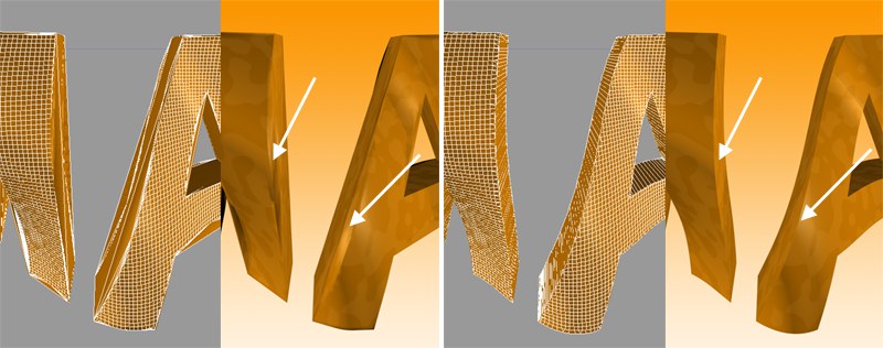 Left: Intermediate points Adaptive; right: Subdivided, applied to an active formula deformation object. Note the defined edges at the right of the image.
This setting controls the maximum spline segment length without adding intermediate points, and is only available if the Intermediate Points parameter is set to Subdivided.
Activate this setting if you want to internally reverse the sequence of the vertices.