Lines
The Lines tab controls which line types (outline, intersections, polygon edges, etc.) are created and which Sketch materials are used to render them.
About lines and layers
To understand how lines work with settings such as Combine (see below), it can be helpful to think about each line type created being given its own layer (internally this is exactly what happens). When Sketch and Toon creates lines for an object, a new layer is created and the line types inserted. If Combine is enabled, all line types that can be merged are placed onto the same layer. If Combine is disabled, each line type is placed onto its own layer.
This means each object produces one or more layers (from each Sketch Style tag and the post effect). The layer priority (i.e. the order in which the layers are rendered) is defined by the tag order, post effect and material priority (defined on the Sketch material’s Main tab), then during rendering the Z-depth is used, followed by the layer priority for all lines of approximately similar Z-depth (lines closest to the camera are drawn on top).
 Types
Types
The options in the top part of the Lines tab control which line types are created. For example, enable the Outline option to create outlines. Some options have extra settings which will appear in the bottom part of the dialog when the option is enabled.
The following line types are available (additional details can be found in the description of the corresponding parameters):
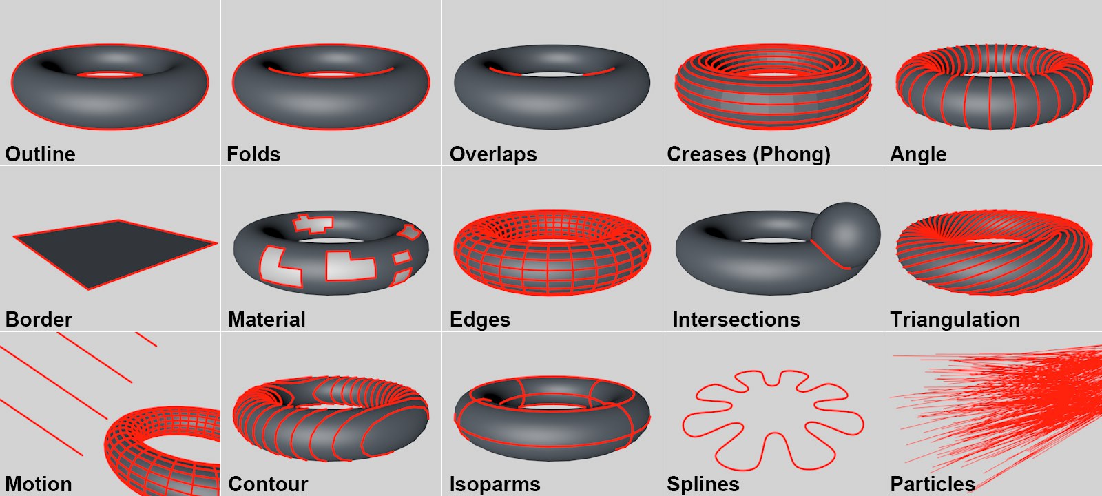 Various line types can be created.
An object’s unhidden contour lines.
A Fold is the edge between a front and rear polygon.
Overlaps are silhouette lines that overlap the mesh, or the difference between Fold and creases.
Non-smoothed object edges.
This renders the edges of two adjoining polygons that lie in a certain angle or within a certain rotational range to each other.
These are edges that only belong to a single polygon.
These are edges that belong to regions of a material assigned to a polygon selection.
Renders each individual edge.
Renders edges that are created when one object intersects another.
A triangulated line is rendered for each quad.
For objects in motion, lines can be calculated in the direction of motion.
Renders lines of equal angle or height.
Isoparms render lines of the same name from generated objects.
Splines will be rendered.
Particles will be rendered. Make sure not to place any objects into the Emitter.
The Combine mode enables you to merge line types in the following ways.
Each line type is created separately and rendered individually on its own layer. If more than one line type produces the same line when using effects such as transparency or patterns, you may notice unwanted results where the lines overlap. An example would be enabling Creases and Angle, which may create lines for the same polygon edges. When strokes are enabled in the Sketch material, the strokes will be limited to lines of the same type.
All line types that use the same Sketch material will be combined on a single layer. This helps to prevent overlapping (see None above). When strokes are enabled in the Sketch material, all line types in this layer are available for the strokes to draw along.
The line types are merged so that only lines which do not overlap between multiple types are created.
The enabled line types are merged to create lines that only exist in more than one line type; this is the opposite effect to Exclusive mode.
See Hidden Cull.
See Hidden Cull under Objects.
To switch off hidden lines, set Hidden Cull to Self and clear the Default Hidden box or local Hidden box.
These settings control which lines are visible and which are hidden. The Hidden Cull mode sets which objects in the scene are used to find out if a line is hidden. In the following examples, the visible lines are black, the hidden lines are red.
In Self mode, only the object which created the line is used to find out if the line is hidden.
 Children mode with Self-Culling disabled (left) and enabled (center).
Children mode uses the parent and its children to find out if a line is hidden.
 Hierarchy mode with Self-Culling disabled (left) and enabled (right).
Hierarchy mode finds the top-most parent and then uses the parent and all its children to find out if a line is hidden.
In this mode, the line is checked against all objects in the scene to find out if it is hidden.
 Object mode with Self-Culling disabled (left) and enabled (right)
This mode uses the objects in the Objects box to find out if a line is hidden.
See also Default Visible
Use the Default Visible and Default Hidden boxes to specify which Sketch material to use for visible lines and which to use for hidden lines (Drag & drop the materials from the Material Manager into the boxes). Leaving a box blank means those lines will not be rendered.
These are the default materials and they are used for all line types except those with their own materials specified in their Visible and Hidden boxes (to display the Visible and Hidden boxes, set Line Materials to Both).
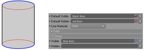 To display the Visible and Hidden boxes for each enabled line type, set Line Materials to Both.
Each box has a triangle button to its right which you can click to access the following commands:
- Clear empties the box. In other words, it unassigns the Sketch material.
- Show In Manager activates the Material Manager and scrolls it if necessary to display the Sketch material.
- Select Element selects the Sketch material in the Material Manager and displays its settings in the Attribute Manager.
Line types
Sketch and Toon offers over a dozen line types. In these pages, you will find a description for each line type and its settings on the Lines tab if it has any. In general, Folds, Creases and Border are all you need for a basic toon.
About line ownership
The object that creates a line owns it. The lines are placed onto a layer that is linked to the object that created them. This can affect things such as outlines — although an outline may look like it goes around multiple objects, internally each object owns its own section of the outline, so if you try and apply a stroke to the outline, it can only go around lines in the same layer, which also means for each object.
Cleaning up with the Sketch Style tag
For general details on using the Sketch Style tag, see Sketch Style tag.
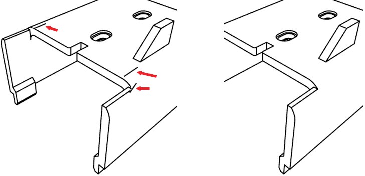 The Sketch Style tag gives you a quick and easy way to remove unwanted lines.
The Sketch Style tag has a Lines selection box that gives you an easy way to remove unwanted lines.
Select the polygons or edges in the problem areas or, if it’s easier the other way around, select all polygons or edges which are not causing the problem. Create a Selection tag for the selection (Select / Save Selection). You can create several Selection tags if you wish.
Drag & drop the Selection tag or tags into the Sketch Style tag’s Lines box (Selections tab). Set Mode to Exclude or Include depending on whether you selected the problem areas or trouble-free areas. Render, and the unwanted lines should be gone.
Outline
 Original, Outline, Folds, Overlaps
These three line types — outline, folds and overlaps — are collectively known as the silhouette-based lines. They appear at each polygon edge where the polygon on one side faces towards the camera (frontface) and the polygon on the other side faces away from the camera (backface).
Folds are the most important silhouette-based lines. A fold is a polygon edge between a frontface polygon and a backface polygon.
Outline generally gives you just the outline of the mesh. It is the same as Folds except that it ignores edges which overlap the mesh.
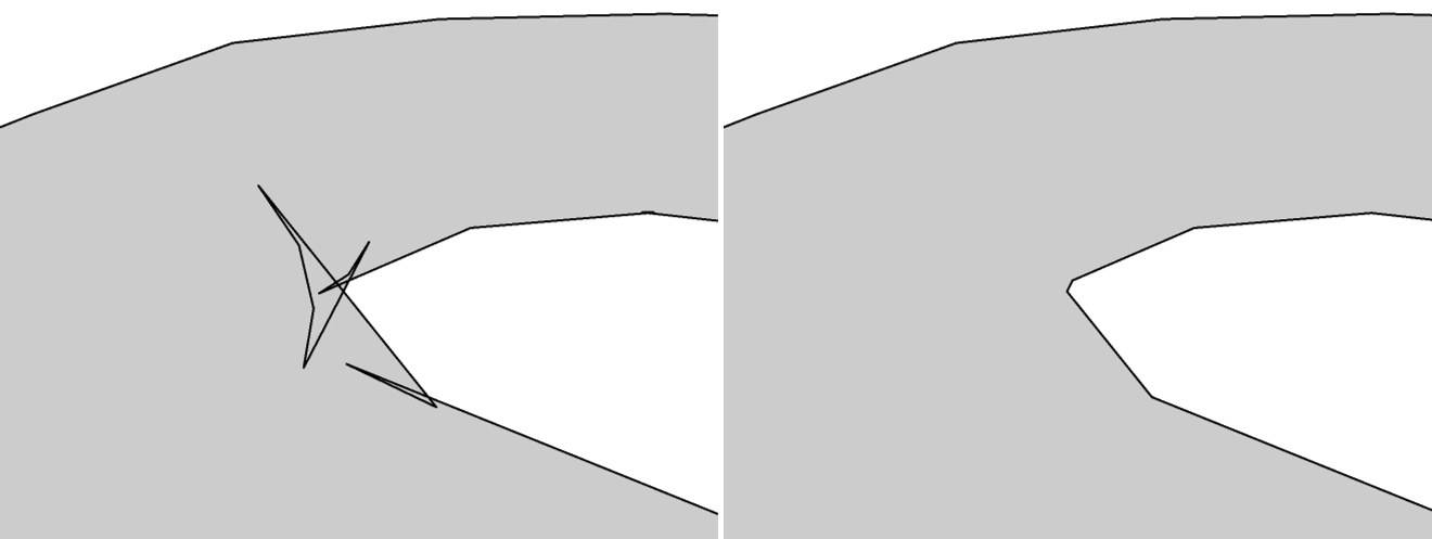
Overlaps is the opposite of Outline. Overlaps are silhouette-based lines which overlap the mesh. Sometimes you may notice small unwanted overlaps. You can often remove these quickly using the Filter Strokes option in the Sketch material on the Strokes tab.
Lines tab settings

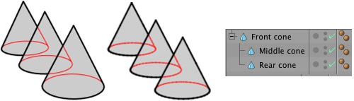
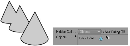
The Outline Culling mode controls which objects will combine their outlines if they overlap.
Outlines are not combined between overlapping objects, but look up Self Culling.
Children mode combines overlapping outlines for the parent and its children.
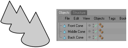
Hierarchy mode looks for the top-most parent and then checks all children of that parent.
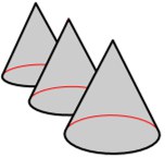
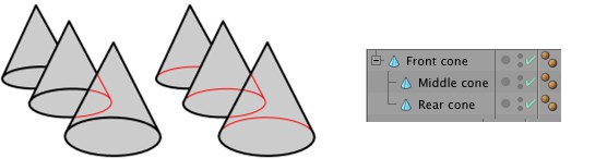
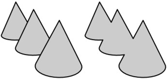
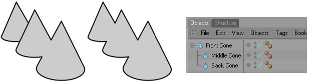 Children mode (left) and Hierarchy mode (center). In Children mode, the back cone has a separate outline because it is not a child of the middle cone.
The overlapping outlines of different objects are combined.
Sketch and Toon combines the outline of each object in the Objects box with the outline of any other object it overlaps.
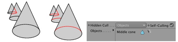
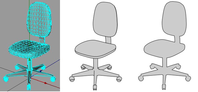 Original object at left: Scene mode, Self-Culling deactivated, Self-Culling activated.
If Self-Culling is active each object’s outline will be combined with the total outline. This will also occur if Outline Culling is set to Self.
If Object is selected in the culling outline menu, objects can be placed via drag & drop into this field to be included in the calculation.
Folds
The Fold Direction setting defines which types of folds are created: all folds (Any), folds in the direction of front to back, or folds in the direction of back to front.
The Fold Direction can be useful if you notice many unwanted lines forming creases.
Generally the Fold Direction should be set to Any, otherwise it reduces the number of lines created, which can result in gaps.
Creases
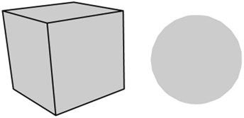
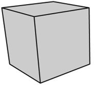
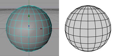
The sphere has no creases because its edges are smoothed by a Phong tag. The cube, on the other hand, has no Phong shading over its edges (angle limit less than 90˚), so each edge results in a crease line.
A crease is any edge not smoothed by aPhong tag (either because the edge has been broken using the Break Phong Shading command on the Structure menu or because the angle between the edge’s polygons exceeds the angle limit in the Phong tag’s settings).
The Min setting helps to prevent creases from appearing in flat parts of the mesh. Each crease is only created if the angle between its polygons is greater than or equal to the Min value.
Angle
Sketch and Toon checks each edge for the angle between its polygons. If the angle is within the Min to Max range, an angle line is created for that edge.
The Min and Max values define the range within which angle lines are created.
Border
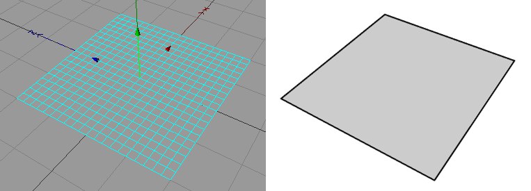
A border is any edge with only one polygon attached to it, such as the outer edges of a Plane object. Borders can also be the outer edges of polygon selections; use a Sketch Style tag to specify which polygon selection tags to use (Drag & drop the Selection tag or tags into the Border box on the Sketch Style tag’s Selections tab).
Material
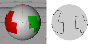
Material lines are the polygon edges around materials restricted to polygon selections or the edges around alpha maps (hard alpha maps work the best).
The following options can be found in the Sketch Style tag.
The Mode defines whether to include or exclude Material tags for edges around alpha maps or materials. Drag & drop the Material tags into the Tags box.
If the Combine option is enabled, Sketch and Toon will combine the outline for any overlapping alpha maps.
Edges
With Edges, lines are generated for each polygon edge unless edge selections are set on the Selections tab of the Sketch Style tag, in which case lines are generated for the selected edges only.
Intersections
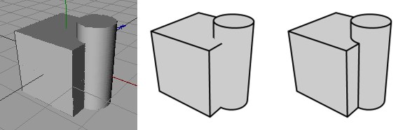 A cube and cylinder, without intersections, with intersections
These are lines where polygons intersect each other.
This mode defines which objects are used to find out if there are intersections.
This mode only produces intersection lines where an object intersects itself.
Children mode checks the parent for intersections with its children. Hierarchy mode looks for the top-most parent and then checks for intersections with any children of that parent.
This creates intersections where any object in the scene intersects any other object.
Sketch and Toon checks the objects in the Objects box for intersection with any other objects in the scene.
Enable this option to switch on lines for where an object intersects itself.
Objects in this field will be included in the calculation.
Triangulation
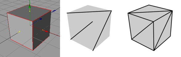 A cube, with Triangulation, with Triangulation & Edges
This creates a triangulation line for each quadrangle.
Motion
These settings create motion lines when an object or polygon selection moves faster than a threshold value. Restricting motion lines to a polygon selection is useful for producing motion lines from arms, legs and so on.
The number of motion lines to create.
Velocity mode creates motion lines based on the object’s current velocity — the greater the velocity, the longer the lines. The lines will only appear if the object is travelling at least as fast as the Threshold velocity.
Trail mode creates motion lines based on the object’s path. To limit the trail to recent frames only, enable the Limit option and set Trail to the desired number of frames.
The minimum speed at which motion lines will be generated.
Enable the Bias option if you want the lines to be zero length at the Threshold velocity, otherwise they will already have some length at the Threshold velocity.
These are lines drawn away from the object or polygon selection based on a 2D projection.
Creates from the line types enabled in the Sketch Style tag or the post effect.
Shapes are created along lines created for the object (e.g., creases, edges or splines; isoparms won’t work), which can be interpreted as a type of motion blur (even though nothing is actually blurred).
Enable the Curves option to creates curves along the motion.
Use the Curve Width setting to adjust the width of the curves.
Use the Curve Height setting to adjust the height of the curves.
Uses a spline object (the Spline LINK control). The spline is used from the XY plane with the dimensions of the Spline object (the object matrix is not used).
A spline object (not spline primitives) can be placed into this field per drag & drop. It will then be used as a movement guide.
Length is the scale for the velocity.
Varies the Length value.
Scale X scales the motion lines.
Scale Y scales the motion lines.
The Offset is the size of the gap between the object or polygon selection and the motion lines. Enable the Relative option to make the offset a percentage of the object’s size on screen — this is useful for objects moving towards or away from the camera.
Squash or stretch the motion lines as they get further away from the object or polygon selection.
Defines the strength of tapering along the X axis.
Controls the strength of tapering along the Y axis.
Use this setting to adjust the strength of the Fade Opacity option.
Thin out and fade the lines as they get further away from the object or polygon selection.
Use this setting to adjust the strength of the Fade Opacity option.
Contour
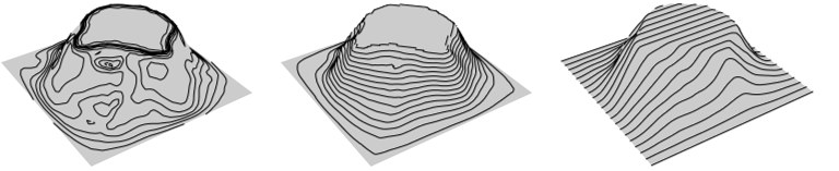 Angle mode, Position mode, UVW mode
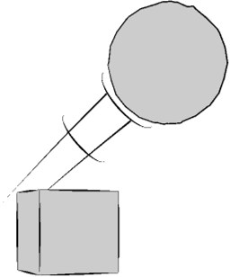
Contour lines help to show the shape of an object. They are especially useful when used with a thick marker style pen such as for the racing car below. There are three modes for contour lines.
- Angle mode creates lines of equal angle from the surface normal to a given axis.
- Position mode creates lines of equal position along an axis, like a map’s altitude lines.
- UVW mode uses the object’s UVW coordinates to create lines in the U or V direction.
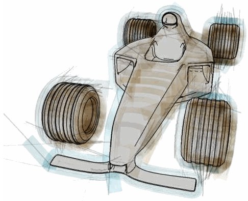 Try using Contour lines with a marker-style pen.
The following modes are available:
The Angle setting defines which axis is used.
In Position mode you can choose the axis along which the contours are created.
In case a given object contains several UVW tags, a tag can be specified using the Sketch Style tag (drag the UVW tag from the Selection tab into the UVW Contour field).
The Angle setting defines which axis is used. You can choose the X, Y or Z axis of the object or world coordinate system, or the view’s (i.e. camera’s) X, Y or Z axis.
This setting defines the range of rotation over which the contour lines will be created. 0° will result in a right angle to the selected axis.
These define the range of angles over which the contour lines will be created. 0° means planar to the axis chosen (see Angle above).
This is the number of contour lines to create.
In Position mode you can choose the axis along which the contours are created. You can choose the X, Y or Z axis of the object or world coordinate system, or the view’s (i.e. camera’s) X, Y or Z axis.
The Spacing mode gives you two ways to control the distance between contour lines: Relative mode and Absolute mode.
Relative mode sets the number of contour lines to create (Steps) and how far along the object they start and end (Min and Max).
Absolute mode sets the distance between each contour line (Step). The Offset value enables you to adjust where the contour lines start along the object.
Use the Variation value to vary the size of the gap between contour lines. The default value of 0 means no variation and the lines will be equal distances apart.
This rotates the axis on which the contour lines are based.
If the object has multiple UVW tags, you can specify which of these should be used via the Sketch Style tag (Drag & drop the UVW tags to be used into the Contour UVW box on the Sketch Style tag’s Selections tab).
 This is which coordinate to use: U or V.
Use this setting to define where a given line should start.
The Min and Max values define how far along the object the lines start (Min) and end (Max).
This is the number of contour lines to create.
Isoparms
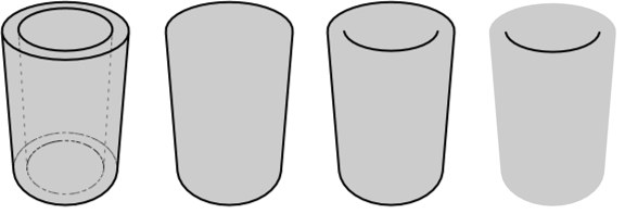
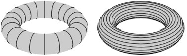
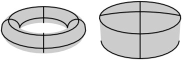 Isoparms for a Torus and Oil Tank object.
These are isoparm lines for objects which use them, such as primitives and Generator objects. Note that these do not work with parent deformers. Also, they do not work with some generator objects such as the Array object and the Instance object.
Splines
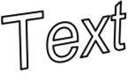
These are lines for spline objects. You can use any type of spline, including text splines and freeform splines. However, they do not work with parent deformers. Nor do they work inside generator objects such as the Array object, Instance object and Symmetry object. As a special case, they will work inside a Subdivision Surfaces object because the Subdivision Surfaces does not affect the spline itself.
Note that a spline segment itself defines a stroke — the direction of the stroke and the line normal (used by the From Line modifier) is taken from the direction of the spline. Enabling strokes has no effect on splines because the spline lines are already strokes.
Particles
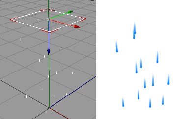
These are lines for particles. They work for particles generated using Thinking Particle’s or Cinema 4D’s standard particle system. As with the spline line type, enabling strokes has no effect because each particle line for a particle is already created as a stroke.
There are two modes for controlling the length of the particle lines.
Velocity mode creates a straight line from each particle’s current position. The line is as long as the particle would travel in one second provided Velocity Scale is set to 100%. Use a higher Velocity Scale value to lengthen the lines or a lower value to shorten them. The line points in the particle’s current direction.
Trail mode creates lines for the trail (i.e. flight paths already travelled) of the particles. The Limit and Trail settings limit the length of each line to the most recent part of the trail. For example, to draw the trail travelled by the particles over the past ten frames, enable Limit and set Trail to 10 F.
Note for the Path Mode, the entire animation must be rendered in the Picture Viewer so the particles are visible.
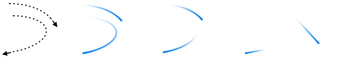
From left to right:
- the flight paths of two particles
- Trail mode with Limited disabled to give the entire trail;
- Trail mode with Limited enabled to give only the most recent part of the trail;
- Velocity mode to produce a straight line from each particle’s current position — the length of the line depends on the particle’s current velocity.
Enables the Limit option.
If, for example, you want to render the path that was covered over the previous ten frames, activate Limit and set Trail to 10B.
Use this setting to define the length of the particle lines.
The On Death setting controls what happens to a line when its particle dies.
With these modes, each line remains or disappears respectively when its particle dies.
When each particle dies, its line gets shorter and shorter until it eventually disappears, like a train disappearing into a tunnel.
Each line fades out gradually after its particle dies.
The Fade value defines how long the line takes to fade out.