Parameter
For Shape Fields (e.g., Spherical Fields), this setting is no longer required because it includes several matrices that are evaluated by the Node.
Any object can be connected to this port (preferably a Null Object) and be used to define the position and direction of the falloff field. In most cases, the Global Matrix output port can be used.
Feed position vectors into this port. The falloff/ color/ direction will be calculated exactly at this position. This value will then be automatically passed on to the Value output port.
Use this setting to define a Normal direction. Only the Shader Field (and then only specific shaders that use a normalized surface direction such as the Fresnel or Falloff shaders) can make use of this.
Here the MoGraph UVW coordinates or UVW texture coordinates for UVW-based Noise Fields are inserted.
• Array Size [1..2147483647]
• Index [0..2147483647]
These Ports are used to output the Field’s effect of step-based Fields (e.g., Step Field). For Array Size, the number of elements (e.g., total object point count, clone count, Thinking Particles count, etc.) can be defined and for Index the element number (e.g., the 7th clone or the 17th particle) whose values should be ascertained.
This port reads out the calculated falloff value (Field channel Value). This value will generally lie between 0 and 1 and can be set to any output value range using the Range Mapper XPresso Node.
This is the color (Color channel) that the Field list produces.
This output port outputs the Field channel Direction as a vector.
With this Port, Thinking Particles effects such as movement/coloring along splines - use the Spline object in the Field list - can, for example, be fed to Nodes (by combining its vector with the particle’s velocity vector and plugging this into the velocity input Port Set P Data).
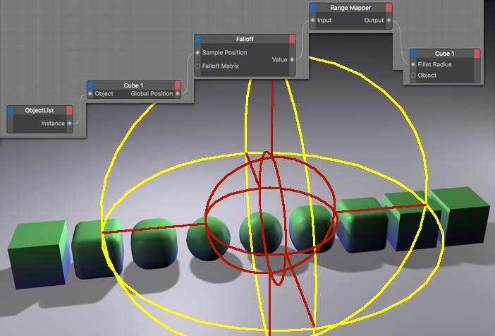 Here the Falloff effects the cube’s Fillet Radius.
The setup shown above scales the Fillet Radius of each cube in relation to its position within the Spherical Field. The Range Mapper Node serves to increase the output value of the Falloff Node from 0 - 1 to 0 - 100. All cubes are contained in the Iterator Node, Object List.