Object Properties
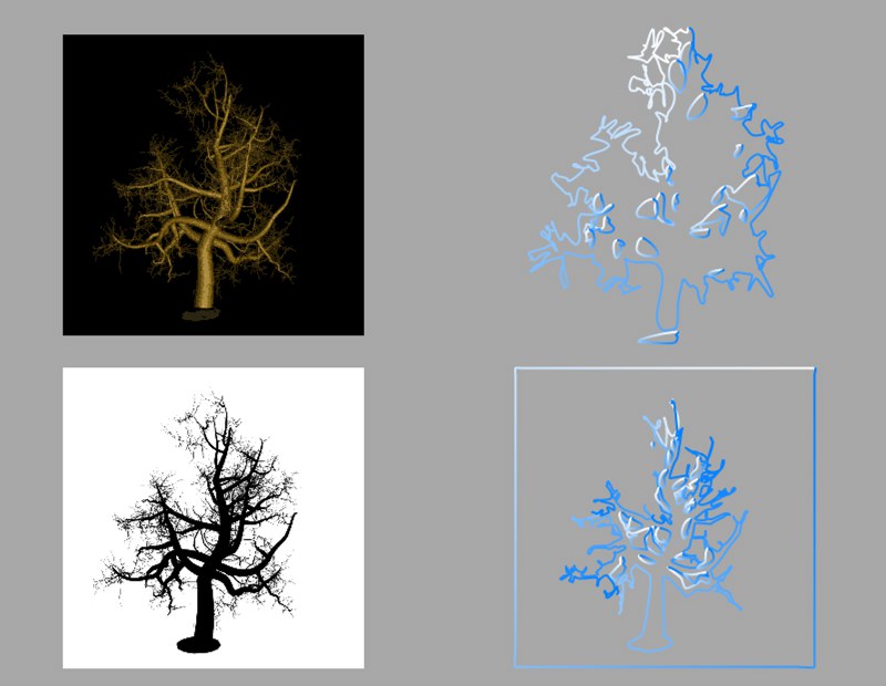
Click the three dots button to open a file selector. Use the file selector to choose the picture that will be converted to splines. Click the arrow left of the filename box to open the picture’s preview.
Keep in mind that only pure black (RGB 0/0/0) is interpreted as a solid background — all other colors will be bordered with a line. The larger the source image, the better the results will be.
 Converting an image (color image with black background and black image with white background).
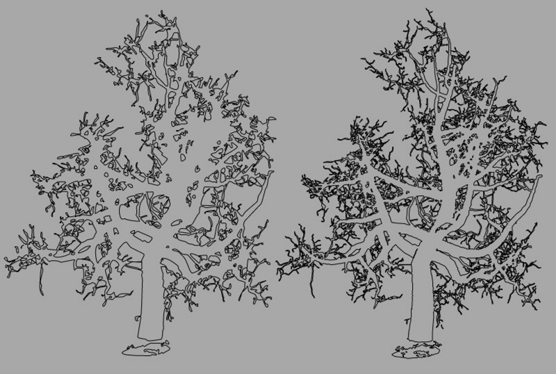 Effect of the image size on the result (left: 512x512 and right: 1024x1024 pixels).
This parameter defines the size in the X direction. The height (Y direction) is calculated automatically using the picture’s aspect ratio and the Width value.
This defines the smoothing of the conversion. The higher the value, the smoother the contour appears. However, more and more detail will also be lost. The smaller the value, the more detail of the original picture will appear in the result. However, this can lead to staircase-like jaggies at the spline’s edges.
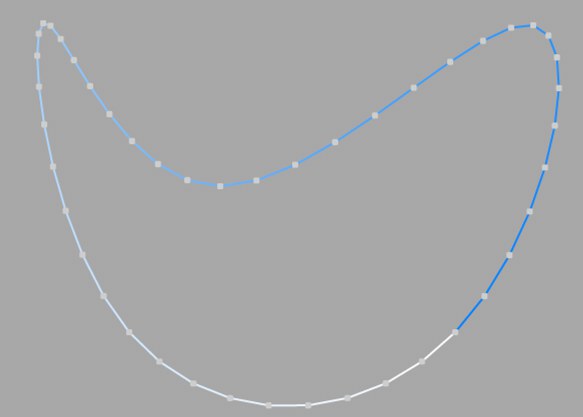
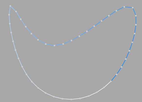
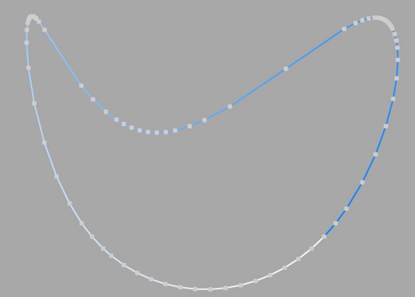
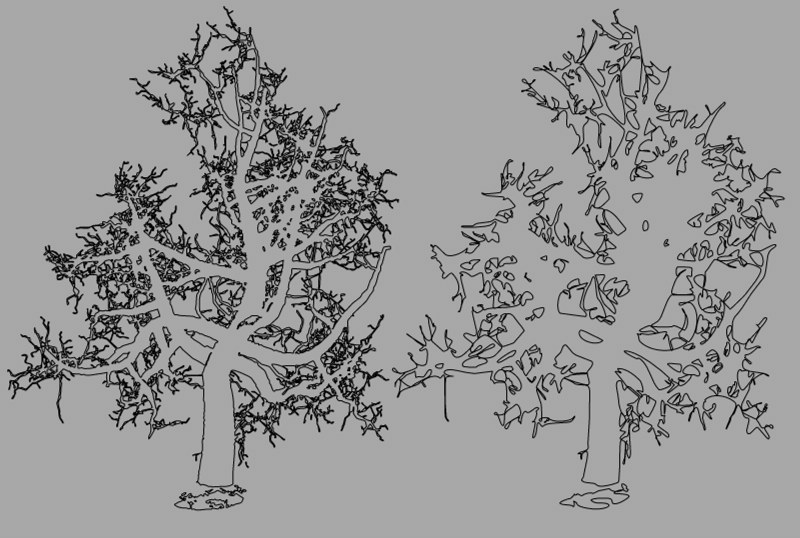 Different tolerance values affect the accuracy of the spline.
With this drop-down list you choose in which of the three planes the spline primitive is created.
Enabling this option will reverse the point order of the spline (see also Spline Primitives.
Here you can define how the spline is further subdivided with intermediate points. This affects the number of subdivisions created when using the spline with Generator objects. Even after you select the Interpolation type from the menu for the Intermediate Points, you can still make changes.
This method of interpolation locates points only at the vertices of a spline, using no additional intermediate points. You cannot enter values into the Number or Angle boxes. For B-splines, the vertices, and therefore points, might not be located on the spline curve.
This interpolation type first locates points at spline vertices. In the case of B-splines, points are located at positions on the spline curve closest to the spline vertices. Number (N) corresponds to the number of intermediate points between vertices. The points are positioned closer together on areas of the spline with more curvature.
You cannot enter values into the Angle box. The interpolation is not affected by reversing the point order.
This interpolation subdivides the spline so that the distance between any two consecutive points, as measured along the spline curvature, is constant. One point is always located at the beginning vertex. For open splines, a point is also located at the ending vertex. Other points generally do not coincide with vertices.
You cannot enter values into the Angle box. The interpolation is not affected by reversing the point order.
Open spline: ((Number + 1) * (number of vertices - 1)) + 1
Closed spline: (Number +1) * number of vertices
So an open spline with four vertices and a number of 2 will contain ((2+1)*(4-1))+1=10 intermediate points. If the spline is then closed, a further (virtual) vertex is added — the number of intermediate points will then be (2+1)*4=12. This ensures that a spline is not more roughly divided when you close it.
This interpolation type sets intermediate points whenever the angle deviation of the curve is larger than the value given in Angle. The points of the resulting curve pass through the vertices. If a spline has several segments, then the value of Angle will apply to each segment.
The Adaptive method gives the best results in rendering, hence it is the default interpolation method.
You cannot enter values into the Number box.
Subdivided is similar to Adaptive. Additional intermediate points will be added until the intermediate segments are shorter than the defined Maximum Length, i.e., the point intervals will not necessarily be equal to the maximum length. Lower values will result in higher quality, along with the disadvantages of working with a high number of points - slower refresh times in the editor view, etc.
Especially the render quality of deformed text can be greatly improved using this method. More or less perfect caps and edges without shading errors can be achieved by setting Maximum Length to the same value as Width in the Extrude object (Caps tab, activated Regular Grid option). The subdivision of the letters and caps will match and must not be done manually.
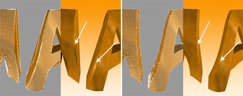 Left: Intermediate points Adaptive; right: Subdivided, applied to an active formula deformation object. Note the defined edges at the right of the image.
This setting controls the maximum spline segment length without adding intermediate points, and is only available if the Intermediate Points parameter is set to Subdivided.