Tag Properties
Controls whether IK is switched on for the tag.
Defines whether the IK chain is solved in 2D or 3D.
In order to understand the difference between these two solvers, you first need to know that each IK solver uses a certain pose of the chain as its starting point for solving the IK. This is usually the pose the chain was in when the IK tag was added.
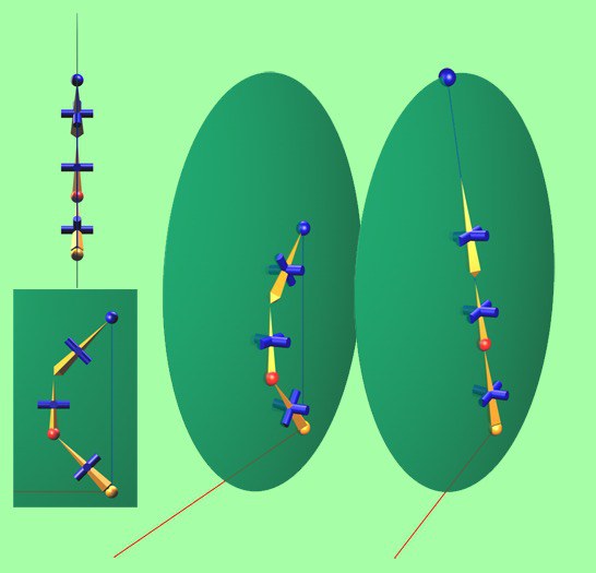
With the 2D option, a plane is created for the IK chain (represented as a disc in the picture). This plane is formed from the following three points in the chain:
- The chain's origin, in other words, the position of the joint to which the tag is assigned.
- The chain's goal (blue sphere).
- The position of the first joint (red sphere) that is not on the line between the origin and goal (shown as a blue line) or pole vector if present.
Each 2D IK chain is solved using this plane, where the pole vector defines in which direction the chain bends. The internal pole vector is used if the chain doesn't have an external one.
The 3D option, on the other hand, uses neither a plane nor a pole vector. Here, the IK chain is solved using only the starting pose and the optimum angles for reaching the goal. In the case of the picture above, where all the joints are lying on a plane, you'll hardly notice a difference between the 2D and 3D options. But the difference becomes apparent in cases such as the one shown in the next picture.
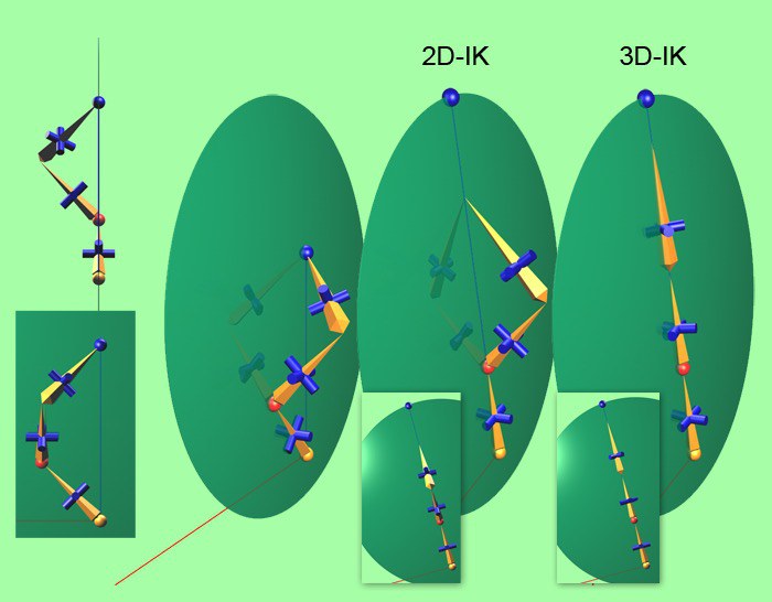
In this example, the third joint has been moved away from the 2D IK plane. The difference between 2D and 3D is clear to see when the chain stretches to reach the goal.
With 2D IK, the only angle that changes is the angle between three joints as if the joints were projected onto the plane. As you can see in the inset at the bottom of the 2D IK example, this angle really does stretch.
You can limit the rotation of this angle for the 2D IK using the Limits group on the Kinematics tab for the joints. The values for Min R.H and Max R.H are used, and are independent of the actual angles of the joints. All other values are ignored in this case. (Note that these values are relative to the starting pose.) As you can tell from the blue cylinders, all other angles for the joints stay the same.
The 3D option, on the other hand, rotates all angles for the joints and does its best to reach the goal. You can see this clearly in the inset for 3D IK by the way the blue crosses are rotated.
In this case, the Limits values do correspond to the actual angles of the joints (although, once again, the values are relative to the starting pose).
As mentioned previously, please note that 3D IK does not use a plane. The plane in the picture is for illustration purposes only, to make it easier to compare the results. The 3D IK uses neither a plane nor a pole vector.
In most cases, you'll find that 2D IK is the best choice for standard characters because it calculates the chain faster and tends to be more stable that the 3D option. 3D IK, on the other hand, is very useful for animating mechanical objects, such as robots.
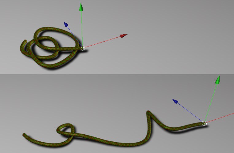
This option is only available if the IK tag is assigned to a point object, in other words, to a polygon object, editable spline, FFD or Bezier object. If you enable this option, instead of the object hierarchy being evaluated, an IK chain is created that directly affects the object's points. This enables you to, for example, quickly animate a garden hose being pulled - simply add an IK tag to a spline that's inside a Sweep object and use this option. In the next example, Point IK has been enabled and the IK Solver has been set to 3D.
Here you can enter the index number of the first point that should be used by the point IK.
Here you can enter the index number of the last point that should be used by the point IK.
Drag & drop the last object in the IK chain into this link field. In the case of the previous example, this would be the last joint object. This is not always the case, however. Usually, it makes sense to have several chains one after the other, such as a chain from the hip to the heel, a chain from the heel to ball, and another from the ball to the toes. The object is entered into the End field automatically when you create an IK chain using the joint tool.
Drag & drop the object you want to use as the goal into this link field. This object is entered automatically if you create the chain using the joint tool. Alternatively, you can add a goal which is again entered into this field automatically using the Add Goal button. The goal is placed in the same position as the object defined by End.
Allows you to blend seamlessly between the chain's current FK pose and the pose calculated for the chain by the IK solver.
Resets the FK state of each Joint to the IK state. This is useful if you have changed Joint positions or rotations in FK mode and want to reset them to their original (based on the IK) state.
Defines the strength of the IK chain's influence. If you lower this value, the chain will take several frames in the animation to reach its goal. Also, you can use several IK tags on the same object and choose different settings for them such as different goals or a different IK solver. You can then use the Strength value to blend between them.
Set this value to 100% if you want the IK to be calculated using the Preferred values on the Kinematics tab as the chain's ending position. Any changes you then make to your character's FK pose will have no influence on the IK solver.
Defines where, on the line from the origin to the goal, the IK chain ends. A value of 100% means the goal will be reached if possible. A value of 0% moves the end of the IK chain to its origin. You can also enter values greater than 100%, in which case the tag will attempt to move the end of the chain beyond the goal by extending the line. Negative values move the end of the chain away from the origin in the opposite direction to the goal.
![]() Pole Vector
Pole Vector
This new option allows you to define which joint axis should be used to orient each joint to the Pole Vector target. Note that the main joint axis (defined by the Axis option in the Object tab of each joint - by default Z) shouldn't be used, since it's the banking axis.
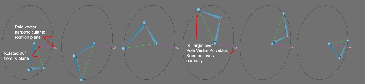
Will rotate the IK plane in relation to the Pole Vector. This is very useful to avoid IK chain flipping issues when taking your character to extreme poses.
For example, say you need a character whose legs have to do a full 360 degrees rotation. Then, simply set the twist to 90 degrees and move your Pole Vector at a 90 degrees angle to the side of the leg to realign your IK chain. Now, your IK goal will never go above the Pole Vector target and cause the chain to flip, since the Pole Vector is on the side.
Here are two illustrations showing the impact it can have. First, without any twist, the IK plane will point the knee directly towards the Pole Vector.
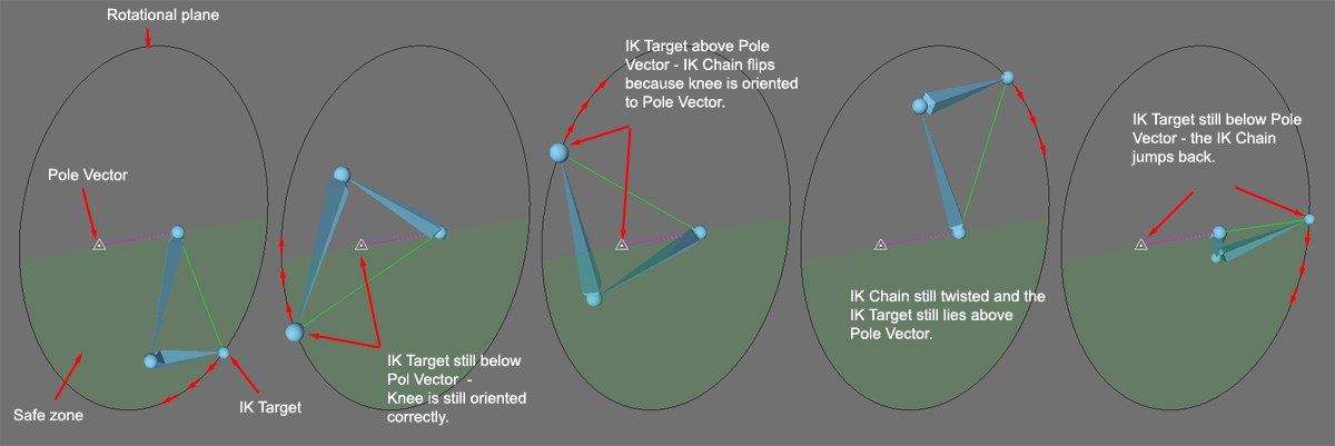
Now, if we set the twist to 90 degrees and reposition the Pole Vector to the side of the IK Chain, the plane of rotation of the chain will never pass through the Pole vector, and the IK chain will not flip around.
This field is only available if IK Solver is set to 2D. Drag & drop any object into this field to use the object as a pole vector for the IK chain. 3D IK does not use pole vectors, hence the field is not available for 3D IK.
Adds a null object at the end of the IK chain as a goal and enters the null object into the Goal link field automatically.
Adds a null object at the position of the first joint in the IK chain as a pole vector and enters the null object into the Pole link field automatically.
![]() Squash/Stretch
Squash/Stretch
Squash and stretch is one of the most commonly used effects in traditional 2D animation. For example, the shape of a bouncing ball will squash upon hitting the floor (or other surface) and stretch upon being repelled. This makes an otherwise mundane motion much more dynamic. The parameters of this group let you easily add this effect to objects in Cinema 4D.
Contrary to the Squash and Stretch Deformer, the squash and stretch effect described here is applied to a chain of bones and can be controlled very precisely.
This value defines to what extend a given IK Chain should be allowed to stretch, whereby a value of 100% will let the chain stretch as far as needed to reach the target object, as defined in the Target field.
This value is closely related to the Stretch value defined in each Joint Object’s Kinematic tab. This setting lets you precisely define the extent to which each bone in the chain should affect the stretch as a whole.
Select how the stretching of the bones of the chain should affect the deformation of the mesh. The following options are available:
Position
Uniform Scale
Bone Scale
Volume Scale
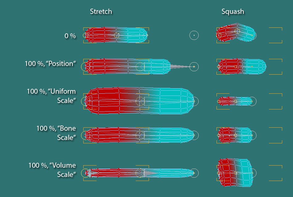
The effect of the various options can be seen in the image above. The Volume Scale setting reflects the effect most commonly used in traditional animation.
Use this slider to limit the maximum IK Chain stretch in Cinema 4D units, independent of the Stretch slider value. The neighboring Clamp option must be enabled in order to edit this slider. The value defined by the Distance slider represents the distance the chain is allowed to stretch beyond its normal maximum stretch distance.
Enable this option to edit the Distance slider.
Use this slider to define how much the chain can be squashed, i.e., be made shorter, before it bends. A value of 100% will result in no bend at all and the chain will only become shorter. This value is closely related to the Stretch value defined in each Joint Object’s Kinematic tab. This setting lets you precisely define the extent to which each bone in the chain should affect the squash as a whole.
Select how the squashing of the bones of the chain should affect the deformation of the mesh. The following options are available:
Position
Uniform Scale
Bone Scale
Volume Scale
The effect of the various options can be seen in the image above. The Volume Scale setting reflects the effect most commonly used in traditional animation.
Use this slider to limit the maximum IK Chain squash in Cinema 4D units, independent of the Squash slider value. The neighboring Clamp option must be enabled in order to edit this slider. The value defined by the Distance slider represents the distance the chain is allowed to be squashed beyond its normal maximum squash distance.
Enable this option to edit the Distance slider.
If changes made to the above settings do not affect your objects, check the Length setting for the Skin Object responsible for the deformations. Make sure None is selected. All other settings will override individual IK settings!