Tag properties
In this tab you can make object-specific settings such as the bendiness of a cloth or its tensile strength. General information about the new Simulation System can be found on those pages.
Unfortunately, some parameters are not constant, but also change depending on the simulation project settings or mesh density. The Substeps and Iteration settings in particular produce a stiffer cloth behavior.
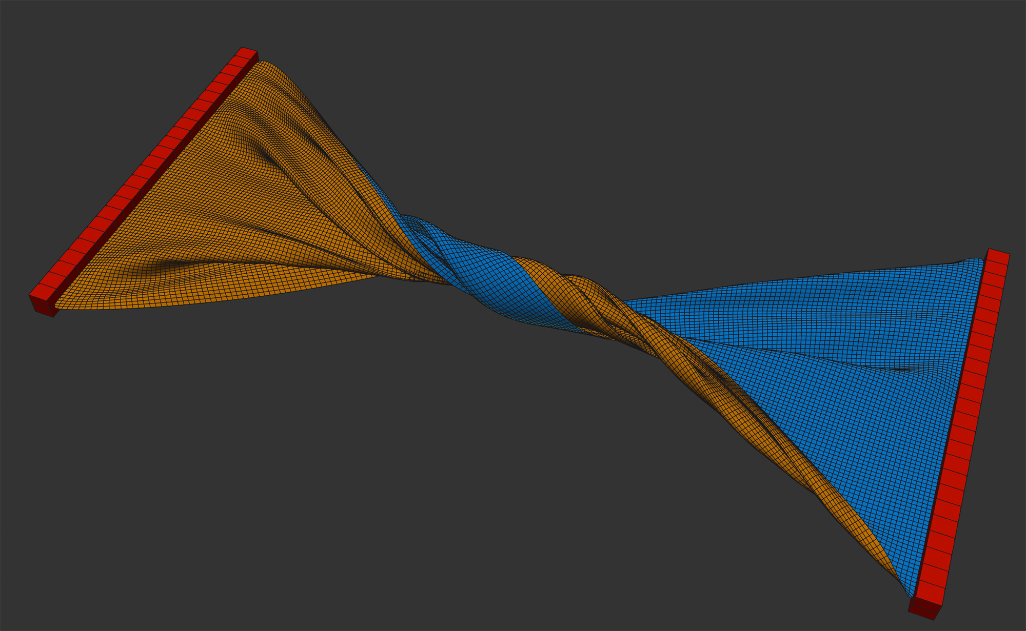
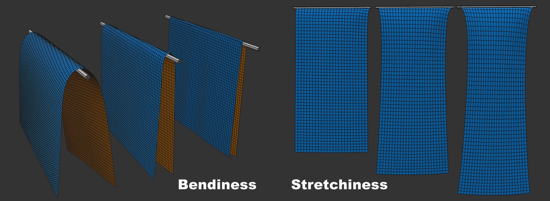 The two parameters Bendiness and Stretchiness each with increasing values.
Imagine a thin square object hanging vertically downward, and you're holding it by the ends of the upper side. Also imagine rotating your hands horizontally 90 degrees.
The Bendiness defines how far the hanging object rotates: small values behave like a thin sheet of metal, increasing values lead to a behavior of aluminum foil up to a towel as values increase.
In other words, Bendiness is a measure of the resistance that a cloth object presents to an external force for angular changes between the object point edges.
Bendiness also depends on the Substeps parameter of the project presets. The larger the Substeps, the stiffer the cloth will be.
With Map, Vertex Maps can be used to define the Bendiness at point level. If you define a maximum value for a related value, the Vertex Map will use this value if Weighting is set to 100%; if set to 50% it will use half the value and so on.
Stretchiness is a measure of how tightly object points are connected by their edges - and any diagonal constraints. Or, put differently, how strong the connected constraints are.
For small values, as is advisable, for example, when simulating real textile fabric without elastic, the points are firmly connected. If, on the other hand, high values are defined, the cloth will stretch like rubber.
With Map you can use vertex maps that specify Stretchiness at the point level. If you define a maximum value for a related value, the Vertex Map will use this value if Weighting is set to 100%; if set to 50% it will use half the value and so on.
See also Substeps, which also affects the Stretchability.
If collisions occur, this setting defines a "springing back" force in the direction of the contact point Normal direction. If, for example, a cloth falls parallel on a plane, the cloth will spring back slightly if higher values are defined. It will repel slightly from the surface. Since textiles normally don't behave this way, the default value is 0.
Be careful with very high values here, otherwise faulty behavior may occur.
Map allows you to use vertex maps that specify bounce at the point level. If you define a maximum value for a related value, the Vertex Map will use this value if Weighting is set to 100%; if set to 50% it will use half the value and so on.
When 2 simulation objects collide or a simulation object touches itself, friction comes into play. This is a measure for the resistance elements have when they rub against one another. Smaller values define correspondingly less friction and larger values increase the friction accordingly.
Contact or collision occurs whenever points, triangles or edges approach closer than defined under Thickness.
Map allows you to use vertex maps that specify friction at the point level. If you define a maximum value for a related value, the Vertex Map will use this value if Weighting is set to 100%; if set to 50% it will use half the value and so on.
When simulation objects get close to each other, the collision case will occur at some point and that is when points, triangles or edges get closer than defined under Thickness.
A very important setting if you want to avoid penetrations. To avoid this, collisions should always occur when the geometry has not yet met (this is why the default is set to 1.5 cm).
If you want to use a very small Thickness for visual reasons - for example, to avoid objects hovering over surfaces as much as possible - it may be useful to increase the Substeps setting in the Simulation Project Settings. This lets you calculate collisions more precisely for faster movements.
If you have very fine mesh geometry, point spacing may turn out to be smaller than Thickness, which would trigger a continuous collision. This is what you want to avoid: Internally, Cinema 4D automatically selects a lesser thickness for the respective points ((80% of the shortest edge that is attached to this point). This means that the defined Thickness value is not fixed and can be undercut internally depending on the mesh density. This applies to self-collision and collision with other Cloth objects/splines. However, for Collision objects (Collision tag), the defined Thickness applies.
Map allows you to use vertex maps that specify Thickness at the point level. If you define a maximum value for a related value, the Vertex Map will use this value if Weighting is set to 100%; if set to 50% it will use half the value and so on.
Here you can define the total mass of the garment, which is initially distributed evenly among all points (can be changed with a vertex map in the Map field below).
Higher masses develop more "thrust" when colliding with lighter ones. In other words: you have greater inertia.
If you want to arrange several garments on top of each other, make sure that a lower layer always holds a larger mass than the one above it. This helps prevent penetrations.
Map allows you to use vertex maps that specify mass at the point level. For the respective setting, define a value that will be spread across all points. If Weighting is set to 100%, the Vertex Map will use precisely this value; if set to 50% only half and so on.
In order for garments to retain their shape, it is necessary to internally place constraints on quads, and to do so in a diagonal fashion. Imagine a single-polygon plane that you're holding at one corner: if constraints were only along the edges, the quad would collapse. Diagonal constraints on the other hand prevent the deformation of the original quad.
You can select from the following:
-
None: no diagonal constraints are used.
-
Simple: 1 diagonal constraint is created per quad. Here, asymmetrical simulation behavior can sometimes occur, e.g., on simple planes. In such cases, switch to the following option:
-
Double: 2 intersecting diagonal constraints are created per quad.
In short, the more constraints there are here, the greater the "shape retention" of the Cloth tag-wearing object.
If the mesh consists only of triangles, this setting has no function (triangles have no diagonal). It only applies to quads - NGons are, by the way, internally made up of triangles and quads, which are processed accordingly.

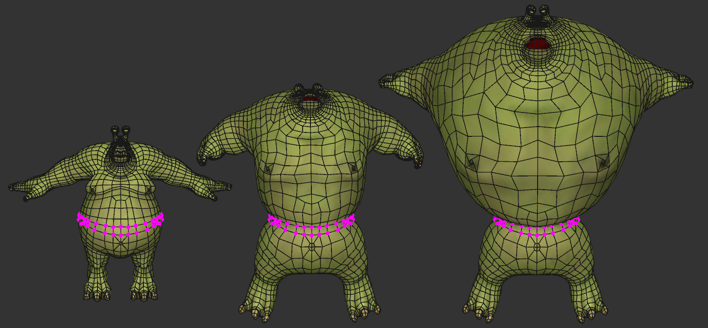 Good old Flabio makes acquaintance with an air pump. Note how regions with greater mesh density (eyes, hands, feet) are more stable.
If you have closed objects, you can inflate them. To do so, activate the Balloon option while the simulation is running and carefully increase the Overpressure value. Increasing the value too quickly can result in penetration occurring.
The Overpressure setting is used to control the actual volume. The default value of 1 produces a neutral behavior and a value of 2 will double the volume. You can even use negative values to create a vacuum. The Balloon option must be enabled to apply the Overpressure setting.
As soon as you activate Balloon, the volume will obey the Overpressure, i.e., even with a value of 1, the behavior will change so that, for example, a ball compressed by collision objects will squeeze out at the sides to maintain the volume. Otherwise the sphere will simply be flattened.
Should a balloon object rupture, the Balloon function will be disabled internally.
A modified Overpressure or an overpressure at the start of simulation each increase within this defined period. This assures a uniform inflation without any penetration. This behavior is similar to real-world behavior: except for a car's airbags, inflation does not occur instantaneously.
Be careful with very small time-frames. The simulation might be overwhelmed with suddenly having to build up a giant volume. Penetrations can then occur very easily.
The parameters of this section revolve around plastic, i.e, permanent, deformations. Imagine a narrow metal strip that you can bend: The strip will give up to a certain degree back to its original state when released but if this degree is exceeded, the strip will start to bend. This is the typical behavior of metals, for example. This does not quite fit within the bounds of a cloth simulation but the more functionality you have the better.
Below you can see the result of plastic deformation:
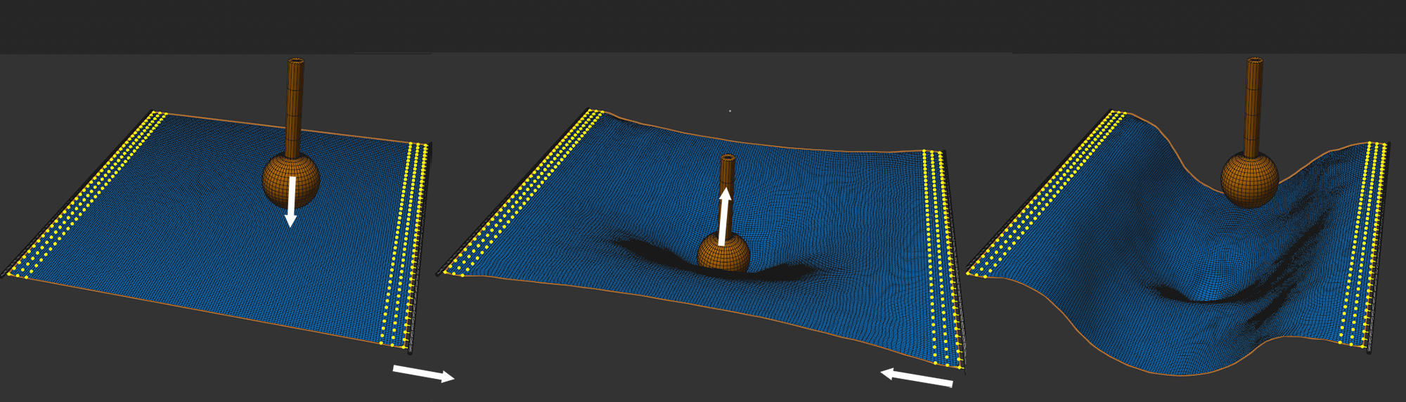 Both bending deformation and stretching deformation are activated here.
A plane is stretched, at the same time a stamp is pressing on it from above, then stretch and punch are retracted. The result is shown on the right as a plane whose length can be defined at will and a permanent indentation from the stamp.
The deformation is split in two in Cinema 4D. As you know, the internal structure of a piece of cloth is defined using the Bendiness and Stretchiness settings to adjust the distance and bend constraints. And these are also responsible for creating the plastic deformation. These can be defined separately. This is why you will find two identical sets of parameters that are described together here.
Here you can define which deformation should behave plastically. Of course both can be activated at the same time. If you take a look at the image above: The continuous plane on the right is a result primarily of the plastic stretch and the indentation at the center is primarily a result of the plastic bend deformation.
If 2 bordering polygons are bent using this value or polygon edges are deformed along their length, a plastic, i.e., permanent deformation will result.
The two values can each also be defined by vertex maps at the point level. Point values of 0% will produce no plastic deformation and 100% in accordance with the Deform Past setting. Intermediate values will be converted proportionally.
Here you can define the degree of deformation: from 0% (none) to 100% (maximum deformation).
The Strength value can be scaled at point level using a Vertex map.
Some metals harden where they are deformed, i.e., their flexibility and elasticity is reduced in these regions. For this you must define positive values.
Other materials on the other hand will soften in the regions in which they are deformed. You must then apply negative values.
With regards to the internal constraints model it means that the constraints will be made harder or softer, respectively.
A value of 0 will disable the hardening effect.
Hardening can be scaled to point level with a Vertex map.
When a garment is stretched beyond a certain extent it begins to tear - the deciding factor here is the elongation of object edges. You can use Tear Guiding to roughly control the course of the tear or Map for more precise control.
Enter here the factor by which an edge may lengthen before it yields at one of its points - the separation will take place at this point.
A vertex map can be loaded here to paint on weaknesses in in specific areas of the clothing structure. If Tear Past is set to 300% and you paint on using 50% or 100% Weighting, the respective points will tear at 150% or according to the edge length defined by Min Tear Past.
This means that you can influence the course of the tear:
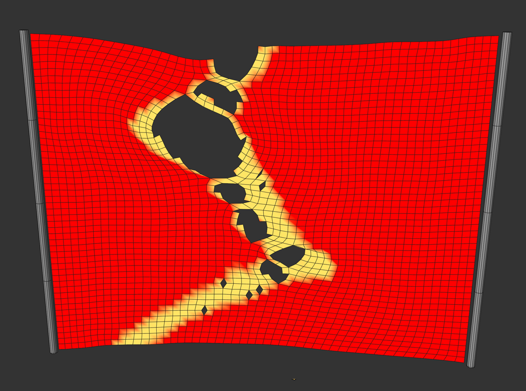
Paint an approximate course of the tear. This is where it will tear when stretched far enough. You can also paint on a linear point row: The tear will then occur exactly along the corresponding edges.
It always depends on the degree to which the individual edges are stretched. If no edges along the painted tear line, no tear will appear.
When you create vertex maps, there are areas that have a 0% weighting. For the tearing process, this means it should tear hear and the garment would be broken down into its individual polygons in extreme cases. If, on the other hand, the default 120% are applied, the respective edges will first tear if stretched to 120%, even if 0% weighting is defined here.
This setting is somewhat more to understand. Simply put, the edges that are part of each tear have an imaginary cone applied to them. Here you can define the angle of the cone. Edges within this cone will not tear.
This can be used to affect tear tendencies. It's much easier to use Vertex Maps to influence this (see previous setting).