Stereoscopic
The stereoscopic camera settings let you define all properties having to do with the creation of two or more images whose perspectives are slightly offset. Detailed information regarding stereoscopy can be found here.
Detailed information about Spherical Camera in VR Stereoscopy can be found here.
This is the normal camera mode without stereoscopy.
Use this mode if you want to render normal stereoscopic images. A double camera will be assumed and each camera will be assigned half of the defined Eye Separation value, left and right, respectively.
Depending on the parameters defined, both cameras will be positioned as follows on the Camera object's X axis:
- Left: left camera is set to 0, right camera is set to + distance between eyes
- Right: left camera is set to -distance between eyes, right camera is set to 0
This value defines the distance between the left and right eye. The default value of 6.5cm reflects the average distance between a human's eyes. Normally, this value should be as small as possible. Greater values will produce a correspondingly larger spatial view but it will also become more strenuous for the viewer to view the scene. Exception: a scene, e.g., a landscape, is depicted that lies far away from the camera.
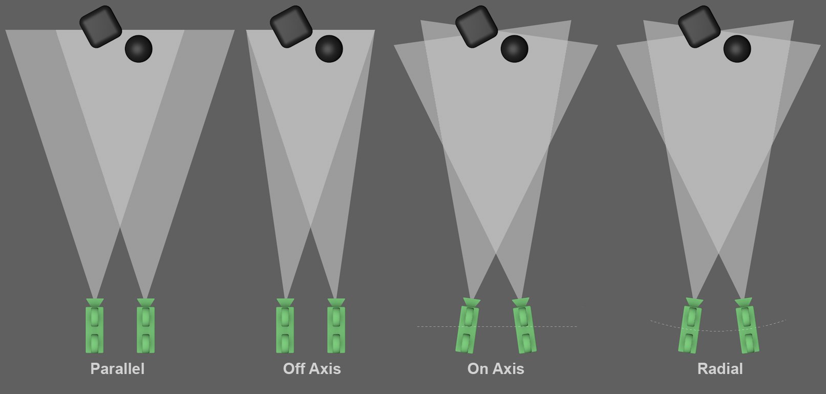 Depending on placement, both (or several) cameras will be oriented differently.
Even though several options are available, most of them are only there for compatibility reasons. For stereoscopic double images you should always (with the exception of special circumstances) set Placement to Off Axis. Each example in the image above uses a double camera only. In the Render Setting’s stereoscopic settings, images can be set to render in channels, i.e., a scene can be rendered from any number of camera perspectives. Their arrangement will also be as shown above.
This is the most simple stereoscopic camera arrangement. Both cameras are positioned parallel to each other (the image axes are also parallel). Stereoscopic images with this type of arrangement only depict objects that lie in front of the projection plane. Hence, the null plane CANNOT be moved by modifying the Zero Parallax value (see also Zero Parallax). This is in contrast to the following three modes.
Basically the same camera arrangement as Parallel but with an offset (similar to Film Offset X), which means that the image axes are no longer parallel but intersect. The zero parallax lies at this point of intersection (see next setting, Zero Parallax). Objects can be depicted to lie spatially either in front of or behind the projection plane (i.e. in or in front of the monitor).
When this mode is selected, both cameras are rotated so their Z axes intersect with the zero parallax. This reflects approximately how the human eye works but is not recommended for the creation of stereoscopic images because a vertical parallax can result. This mode is also referred to as "toe-in".
This mode is similar to On Axis except that both cameras don't lie on the Z axis but on an arc (whose center point lies on the point of intersection of both cameras’ zero parallaxes).
Enable this option if both left and right cameras (instead of only a single camera) should be displayed in the Viewport.
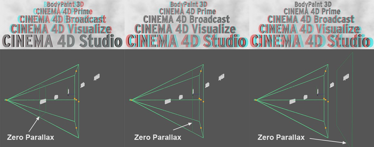
The zero parallax is a virtual plane that lies vertically to the camera's angle of view and defines where the projection plane lies, i.e., the plane that represents the monitor screen at its depth. Objects that lie in front of this plane in the direction of the camera protrude spatially out of the monitor in the direction of the viewer; objects that lie behind this plane lie "within" the monitor.
In the Viewport, the zero parallax is displayed as the dark green camera plane at the center.
If you link the Zero Parallax to the Focus Distance via XPresso you can adjust the zero parallax interactively in the Viewport using handles.
If you want to play it safe, select 90 and place all visible objects in the direction of the camera and behind this plane.
The Auto Planes do not affect rendering! They only serve as visual references that you can adjust manually. If you determine via test renderings that the optimal spatial impression within a given distance from the camera has been achieved (objects that, for example, lie too close to the camera – while the zero parallax is positioned far away – can only be seen with great effort by the human eye), then you can define these planes accordingly and can place objects in the Viewport correctly within the resultingly restricted space.
The options 70 and 90 represent a parallax of 70 and 90 arc seconds, respectively, for the near plane. These values are described in technical literature as values at which the human eye can perceive spatially with normal effort. Therefore, objects should lie behind this near plane.
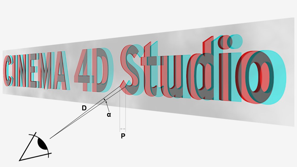
A formula even exists that defines the maximum parallax (distance between red and cyan (anaglyph)):
P = tan a * D
Whereby P = Parallax, D = Distance of the viewer from the projection plane (e.g., the monitor), a = Angle between 2 points that the eye can comfortably perceive (this should be max. 1.5° or somewhat less).
For a monitor and an average distance between eyes and monitor of 50 cm, an average reference value of 13 mm results.
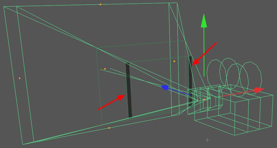
Enables or disables the display of critical regions (that can be seen by each camera). The Show All Cameras option must also be enabled.
Stereoscopic rendering with a Spherical Camera
Special settings are available if you want to make the 360° view of a Spherical Camera stereoscopic. The left and right eye views will be combined to a single image (left = top; right = bottom).
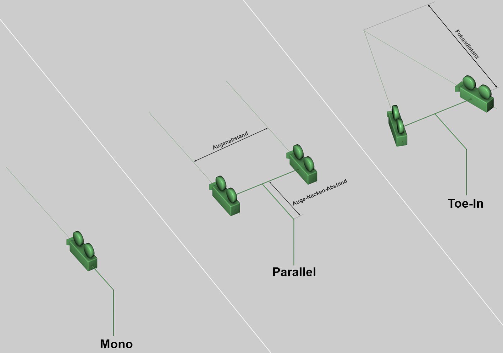 The various Stereo modes with the camera axes (the cameras are rotated internally for rendering panoramas).
The following options are available:
- Mono: no stereoscopic images will be rendered.
- Parallel: both cameras will be arranged with parallel axes of view.
- Toe-in: both cameras’ axes of view will cross. The point of intersection can be defined using the Focal Distance.
The primary difference between both stereo modes lies in the definition of the null paralllaxe, i.e., the distance from the camera at which no parallaxe is generated. This spatial depth can be seen in the Viewport. If Toe-In is selected, the null parallaxe will be defined using the Focal Distance setting and cannot be subsequently modified. If Parallel is selected, the null parallaxe is infinite and can be subsequently modified (by moving the left and right perspectives).
Here you can define how both stereo images should be arranged or which one should be rendered alone.
This value defines the distance between both cameras/eyes. The default distance of 6.5 cm represents the average distance between human eyes.
Depending on which target model is rendered (this system works according to the Oculus Rift targeting system), you can define the horizontal distance from the neck "Atlas" (or C1) to the eyes (see image above). The Atlas is the rotational joint around which the head rotates, including the (forward-lying) eyes. The camera's rotational point will therefore no longer lie at the center of both cameras if the Eye to Neck Distance is set to 0.
If Stereo Mode is set to Toe-In, you can use this setting to define where the null parallaxe should lie. Objects that lie in front of this point and face in the camera's direction of view will protrude out of the monitor towards the viewer; objects that lie behind this point will more-or-less "sink" into the monitor.
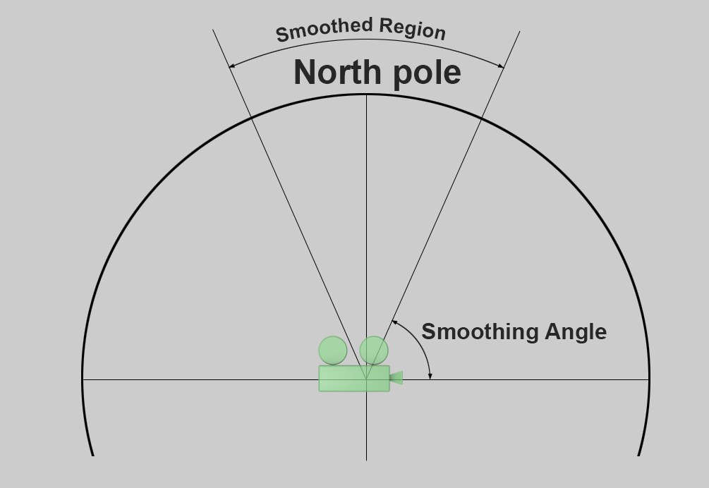
For technical reasons, stereoscopy cannot be rendered correctly around the poles. To prevent unwanted artefacting, the stereo effect can be gradually faded in these regions. In most cases, this can be done with no problem because the visually important elements mostly occur horizontally around the camera's location (and not vertically above or below it).
The smoothing can be defined separately for top and bottom poles. In the region in which the smoothing takes place the views will be equalized with the left and right cameras until they are identical with the maximum possible smoothing. The smoothing types are described below.
Bottom Smoothing Angle[0..90°]
How smoothing will be done from the start to the pole is determined by the using the Linear option (with linearly increasing strength, i.e., abrupt deployment) or the Exponential (with exponentially increasing strength, i.e., gradual deployment) using the defined defined Smoothing Angle. The Top/Bottom Polx Exp settings can be used to affect the Exponential option.