Note:
An active selection is automatically saved if the Edit Mode is changed. An edge selection is therefore retained if, for example, you switch to Point Mode and later switch back to Edge Mode.
The mesh actions menu allows you to apply different operations on the selected mesh. Some of these actions also offer additional options that can be opened by clicking on the cogwheel icons that are shown next to the commands.
Table of content
The available Modeling Actions and Selection Actions are based on the active Edit Mode (Object, Faces, Edges, Points), that can be switched from the icons on the top of the Viewport or from the drop down menu in the Toolbar that is found on the right side of the viewport by default.
|
|
Note: An active selection is automatically saved if the Edit Mode is changed. An edge selection is therefore retained if, for example, you switch to Point Mode and later switch back to Edge Mode. |
Most modeling tools and modeling actions can be applied to a specific region of a mesh by using selections. You can create individual point, edge oder polygon selections bei using the Select Tool. Just be sure to activate the needed Edit Mode first. This tool offers various modes and options.
While selecting you can always use the Add Selection/Subtract Selection modifier buttons in the Shortcuts Toolbar on the left to add or subtract elements to the current selection.
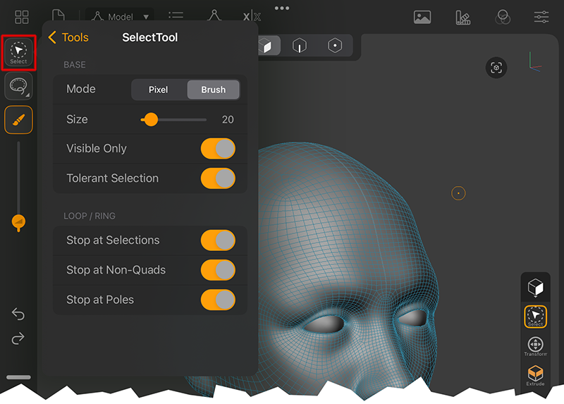 Activate the Select Tool in the right Toolbar. Then click on the Select Tool icon on the upper left to acess its settings.
Mode: The Select Tool offers two modes:
Pixel: You can only select by tapping on an element, not by painting over an area. This mode is especially usefull for using the additional tools, like Lasso, Rectangle, Square, Ellipse or Circle to select larger areas in one step. More info on this is found below.
Brush: This activates the typical paint behaviour to draw your selection by moving over the surface in one continuous movement.
Instead of moving over the elements to be selected you can also use a classic Lasso selection method or use shapes, like a Circle or a Rectangle to select an area. Just choose from the option list found right below the Select Tool icon in the left Toolbar (see also the image above). To activate the chosen selection shape you have to keep one of the selection modifier buttons pressed. It is recommended to use the Pixel Mode for the Select Tool with it, as this also allows you to start drawing the selection shape directly over a mesh, not having to start drawing in an empty area of the Viewport.
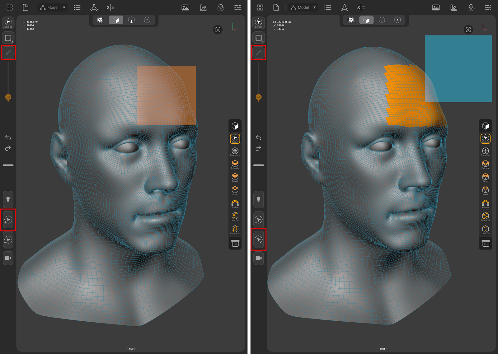 Adding and subtracting a rectangular selection shape.
As you can see in the image above, it is recommendet to keep the Pixel Mode active (see highlighted icon on the upper left) and combine a tap+drag action with one of the two selection modifier buttons, to add or subtract a selection. Added selection shapes are drawn in an orange color, subtracted shapes have a blue color.
Ring and Loop selections provide an easy way to add complex selections that follow the specified direction of the edges or polygons. For this to work, you have to double-tap on any single edge of the mesh. When dealing with high density meshes you might have to zoom in close enough or lower the Size value of the tool to hit just a single edge. When you are in Polygon Edit Mode, a so-called Ring Selection is created that follows the strip of polygons on the side of the double-tapped edge.
When using the Edge Edit Mode, a double-tap on an edge will create a Loop Selection which follows the direction of the edge.
The process is a bit different in Point mode. First select one point and then double-tap on a second point that shares an edge with the first point. This way you can also create a Loop selection with points (see example images below).
To control the creation of Ring and Loop selections there are also additional options available at the Select Tool settings. These are described right below.
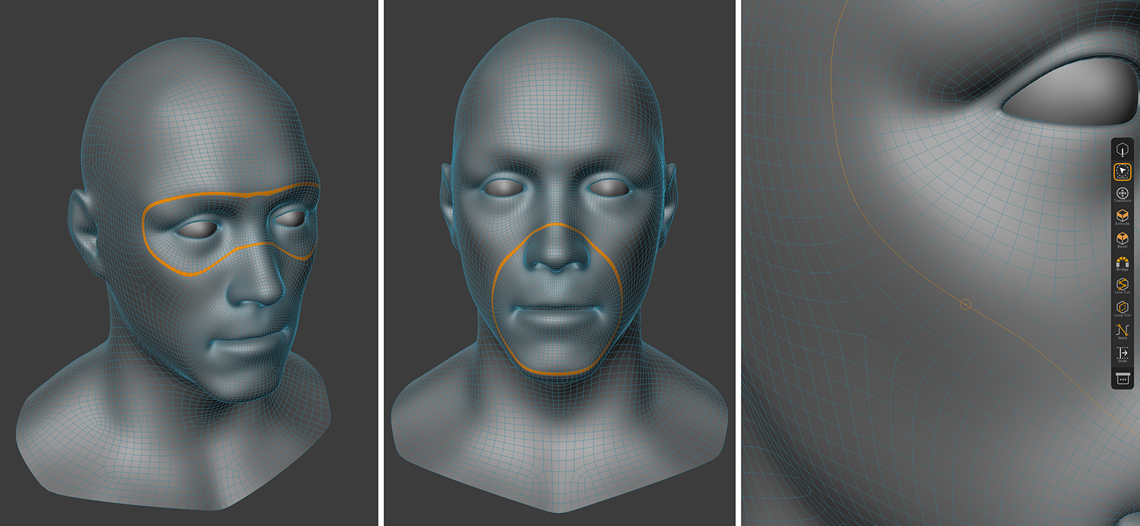 The two images on the left show examples of Ring selections of polygons, the image on the right shows a Loop selection of edges.
When working with edges, you can also hold the Subtract Selection modifier button while double-tapping an edge and will receive an edge Ring selection. The same technique also works with points. For this you again have to first select one point of an edge and then double-tap on the other edge point (see images below).
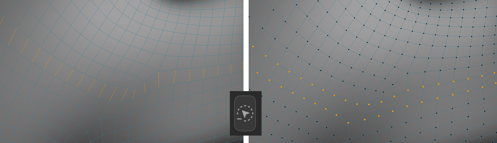 A Ring selection of edges and a Ring selection of points, created by holding the Subtract Selection modifier button.
Beside the Mode setting, the Select Tool also offers these options and settings:
Size: This is the radius used in Paint Mode. This value is also accessible directly as a value slider below the Select Tool icon in the left Toolbar.
Visible Only: Only visible elements in the viewport can be selected. This way you cannot select elements on the backside of a mesh.
Tolerant Selection: This only applies to the selectin of edges or polygons. Having this option activated, you can select edges or polygons even by selection just one point of an edge or one edge of a polygon.
The following options are offered to control the creation of Ring and Loop selections (double-tap an edge with Select Tool Paint Mode):
Stop at Selections: Whenever an existing selection is in the way of a to be created Ring or Loop selection, it will stop the selection path at that position.
Stop at Non-Quads: If a triangle shaped polygon or a N-gon is touched by a Ring or Loop selection, this ends the selection.Otherwise, an unpredictable bending of the selection path can occur at such polygons.
Stop at Poles: The path of a Polygon Ring selection will stop automatically when reaching a point that is only surrounded by triangles (like a north or south pole at a Standard Sphere primitive). When creating an Edge Loop selection, a pole is a point that is an element of multiple polygons and whose polygon count is not 2 (edge) or 4 (regular loop).
Note:
The Modeling Actions menu will not open if there is no Editable Mesh selected. To select a mesh, go to the Object List and tap on its name. Remember that Editable Meshes are the ones with the triangle with points icon.
Note:
The available Modeling Actions depend on the Edit Mode. Some commands also require a Point, Edge or Face selection.
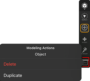
This image shows the Modeling Actions menu while in Object mode.
|
|
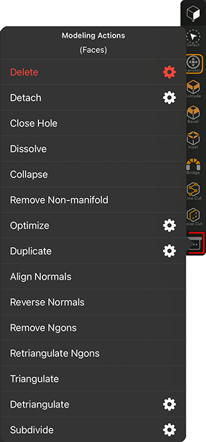
This image shows the Modeling Actions menu while in Faces mode.
|
|
Close Hole: Having an open area that is completely surrounded by faces, this command will close that opening with a patch of polygons that tries to keep the flow and density of the mesh. To make this work, all polygons along the opening have to be selected. If the selected polygons surround several openings, you might have to call this command several times as only one hole is closed at a time.
Dissolve: All selected polygons that form a contiguous island are converted into a single N-gon. Polygons can have only 3 or 4 edges, but N-gons have no restriction on the number of points or edges. The only drawback is that although complex and even curved surfaces can be represented by an N-gon, there are no editable points within the surface of the N-gon. Only the edges and points on the edge of the N-gon are normally editable. This limits the possibilities to shape an N-gon in all dimensions. On the positive side, however, N-gons can be selected with a single mouse click and edited with the modeling tools like normal polygons.
Collapse: The selected polygons will be merged into a single point in the center of the polygon group.
Remove Non-manifold: Whenever more than two polygons meet at an edge, it is a mathematically undefined surface. The command therefore splits the surface at this edge. Thus the action corresponds to using the Detach command for the non-permissible surface at the edge. To ensure that all edges of the object are checked accordingly, make sure that no polygon is selected when the command is called.
Optimize: This action can be used to find and remove double or overlapping elements, such as points that are in a very short distance towards each other. Within the tools options you can set this distance with the Tolerance value. Note that this action is limited to the elements of the current selection. If you like to optimize the complete mesh, Clear any edge selection first. There are also some options available for this action:
Polygons: Polygons, that don't contribute to the visible surface (for instance, when all points are positioned on a straight line), are automatically removed.
Unused Points: Points, that are not a part of any edge or polygon are removed.
Points: Points, that are placed within a very close radius (set by the Tolerance value) are welded into a single point.
Duplicate: The selected polygons can get duplicated, scaled, rotated and moved along the chosen object Axis. The command offers these settings:
Clones: Defines the number of clones along the selected object Axis. Offset, Scale and Rotation specify the parameters for the final clone. The intermediate clones use interpolated values.
Offset: Gives the distance from the start element to the last clone along the selected object Axis. All intermediate clones are distributed evenly over this distance.
Holes: With this percentage value (0=0%, 1=100%) you can define the number of cloned elements that you want to be omitted from the total. With a value of 0 the full number of clones is created. With 0.5 (=50%) only half will be created. The omitted elements are randomly selected. With a value of 1 (=100%) no new elements at all will be created.
Scale: This parameter enables you to scale the clones. The scale of the clones will increase gradually all the way to the last clone. Enter the size of the final clone as a percentage of the start element's size (0=0%, 1=100%). For example, if you enter a vaue of 0.5 (=50%), the last clone will be half as large as the initial clone. A value of 1 (=100%) will not modify the size of subsequent clones.
Axis: Defines the object axis about which the clones are to be moved or rotated.
Rotation: Defines the angle through which the clones are rotated. You can also use negative values here.
Move Variation: By default, all clones are assigned a fixed position that depends on the above settings. You may vary these positions using Move Variation. For example, if you set the Move Variation value for Y to 0.1, each clone can deviate from -0.1 to 0.1 units in their Y position.
Scale Variation: Defines the variation in the size of the clones as a percentage, with 0=0% and 1=100%. At 1 the size is not varied. Entering 0.5 for the X value means that the X size of the individual elements can vary between 50% and 100%.
Rotation Variation: Each element is assigned its own virtual axis. The element may then be rotated randomly around its axis with the value entered here.
Uniform Scale:If this option is enabled, the values entered for X, Y and Z are used for relative scaling. For example, with Uniform Scale enabled, X set to 2, Y to 1 and Z to 0.5, the ratio of scaling is 2:1:0.5; the individual elements can then be scaled only according to this ratio. If this option is disabled, the axes of the individual elements can be varied in scale independently.
Align Normals: When creating polygons you may sometimes create surfaces whose Normals point in the wrong direction. Using Align Normals, you can quickly correct the direction of selected polygons.
Reverse Normals: This action is similar to Align Normals. Here, however, the Normals are reversed. If no polygons are selected, all the Normals of a selected object are reversed. With an active selection only the Normals of the selected surfaces are considered.
Remove Ngons: This action automatically converts existing N-Gons to normal triangles and quads. Point, edge or polygon selections can also be used if N-Gons should only be converted in specific regions.
Retriangulate Ngons: Internally, N-gons consist of triangles and quads. The arrangement of these polygons is defined when the N-gons are created and will not change, even if the position of the edge points change. This action can be used to update the arrangement of the polygons in existing N-gons.
Triangulate: Triangulate converts all of an object's polygons to triangles. It analyses polygon selections (only these will be subdivided). In all other modes (Edges, Points), the entire object will be triangulated.
Detriangulate: If a given object is only made up of triangles, this action will convert these triangles back to quads or N-gons. The modeling action offrs the following options:
Create N-gon: Enable this option if you want to create a common N-gon from triangles. The Flatness Angle's Angle wetting will be used automatically. With increasing values it can happen that the object's shape changes - up to a complete collapse. You should generally start with small values.
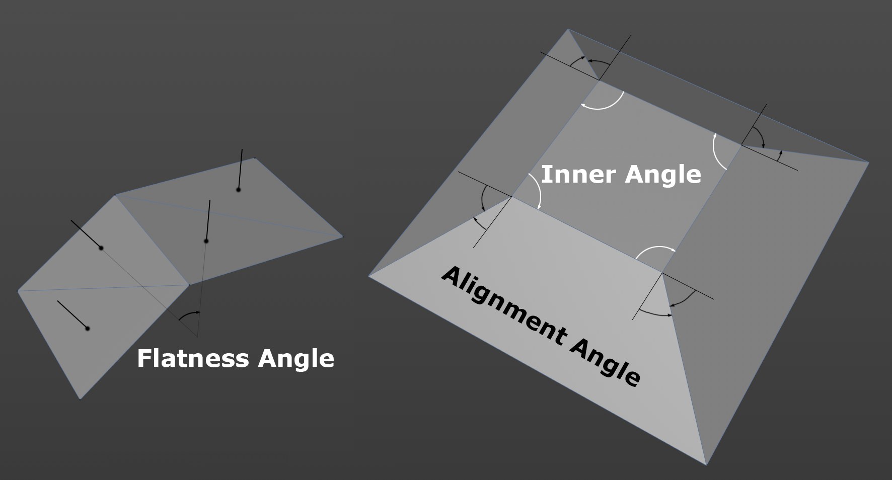 The 3 angle types that can be used by the following options. Note on the right that you can define the angle to be used in the resulting quads.
Flatness Angle: Activate this option to make use of the following Angle value.
Angle: Here you can define the maximum allowable deviation of Normal angles between adjacent triangles to which quads or N-gons can be created. Or, put more simply, if there is a corner where two adjacent triangles meet, a higher value must be defined for these to be converted.
Internal Angle: Activate this option to make use of the following Angle value.
Angle: Here you can define the degree to which the internal angle of the resulting quad can deviate from 90° so a quad can be created. The higher the value, the more the resulting quads can deviate from a quadratic shape.
Alignment Angle: Activate this option to make use of the following Angle value.
Angle: If you imagine the edges of a quad extending beyond the outer points as a line, angles can be created between these imaginary lines and the adjacent edges (if the mesh is not planar). The value defined here defines the maximum allowable angle deviation for the resulting quad. If the deviation were greater, no quad will be created.
Keep UV Boundary: Enable this option if you want to maintain the edges of UV islands and with them the corresponding polygon edges. Note that the UV coordinates will in some cases be modified but this should be irrelevant in most cases since the UV coordinates are mostly only important after the modeling process.
Keep Phong Edge Breaks: Phong edges that are defined using Create Shading Breaks By Angle (see Mesh Commands) will remain unchanged if this option is enabled.
Keep Mesh Attributes: Points can save multiple values, such as colors. If the algorithm removes related triangles, the values saved would change. Enable this option to prevent this. Corresponding edges will not be modified or removed.
Subdivide: With this action you can subdivide faces. If no polygons are selected, all polygons are partitioned. Otherwise, only the selected polygons are subdivided. The results can be similar compared to using the Subdivision Level from the objects Display Settings, but here the calculation is applied directly to the mesh and therefore cannot be tweaked later. The tool also offers additional options:
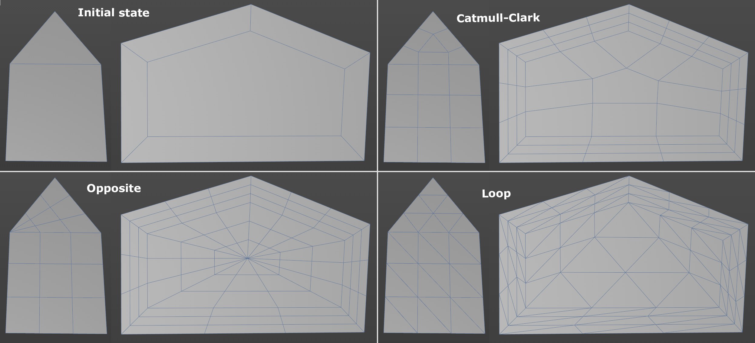 The 3 angle types that can be used by the following options. Note on the right that you can define the angle to be used in the resulting quads.
Mode (also see image above):
Catmull-Clark: Subdivides - as much as possible - using quads.
Loop: Subdivides exclusively using triangles.
Opposite: Handles N-gons particularly well since it creates edge loops around a point at the center (quadrangles are created via Catmull-Clark and triangles are created by connecting the starting point with the opposite edge).
Smooth: With this option enabled the object is subdivided using the Subdivision Surface formula. Point positions that already exist are modified to round the structure of the surface. If this option is disabled, existing point positions are maintained and the surface is not smoothed when subdividing.
Iterations(available if Smooth is on): Here you can enter the number of subdivision steps that should take place. The polygon or point count will increase exponentially with each step. You should therefore be careful when increasing the number of steps. You can always just use the values 1 or 2, evaluate the result and call the command again to increase the subdivisions further in a second step if needed.
Subdivisions (available if Smooth is off): This defines the number of times each individual edge should be subdivided. If set to 3, each edge will be cut 3 times.
Angle(available if Smooth is on): Defines the maximum angle the surfaces can have to each other while still maintaining a hard edge. If this angle is smaller than the defined value, the edge will be rounded.
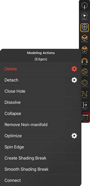
This image shows the Modeling Actions menu while in Edges mode. Some of the available actions are also avilable in Faces mode and have been described already. That's why we focus on the edge specific commands and options here:
|
|
Close Hole: Having an open area that is completely surrounded by faces (and selected edges), this command will close that opening with a patch of polygons that tries to keep the flow and density of the mesh. To make this work, all edges along the opening have to be selected. If the selected edges surround several openings, you might have to call this command several times as only one hole is closed at a time.
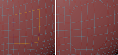
Dissolve: All selected edges are removed from the mesh (see example in the image below). The polygons that were bounded on one side by these edges are combined into N-gons. N-gons are faces that can be defined by more than four edges. The only drawback is that although complex and even curved surfaces can be represented by an N-gon, there are no editable points within the surface of the N-gon. Only the edges and points on the edge of the N-gon are normally editable. This limits the possibilities to shape an N-gon in all dimensions. On the positive side, however, N-gons can be selected with a single mouse click and edited with the modeling tools like normal polygons.
Collapse: The selected edges will be merged into a single point in the center of the edge group.
Remove Non-manifold: Whenever more than two polygons meet at an edge, it is a mathematically undefined surface. The command therefore splits the surface at this edge. Thus the action corresponds to using the Detach command for the non-permissible surface at the edge. To ensure that all edges of the object are checked accordingly, make sure that no edge selection is active when the command is called.
Optimize: This action can be used to find and remove double or overlapping elements, such as points that are in a very short distance towards each other. Within the tools options you can set this distance with the Tolerance value. Note that this action is limited to the elements of the current selection. If you like to optimize the complete mesh, Clear any edge selection first. There are also some options available for this action:
Polygons: Polygons, that don't contribute to the visible surface (for instance, when all points are positioned on a straight line), are automatically removed.
Unused Points: Points, that are not a part of any edge or polygon are removed.
Points: Points, that are placed within a very close radius (set by the Tolerance value) are welded into a single point.
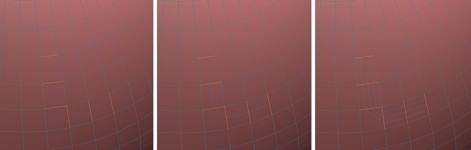
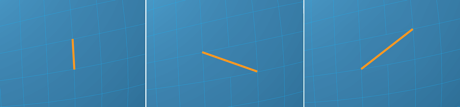 Example of the use of the Spin Edges command. The position of the selected edge changes each time the command is called until the original direction is reached again.
Spin Edge: This command to turns (spins) the selected edges (several can be turned simultaneously) of two adjacent polygons and connects them to the neighboring two points. Why would anyone need to do this? This way the polygon flow can be altered or poles smoothed (e.g., if five or more edges meet at a single point).
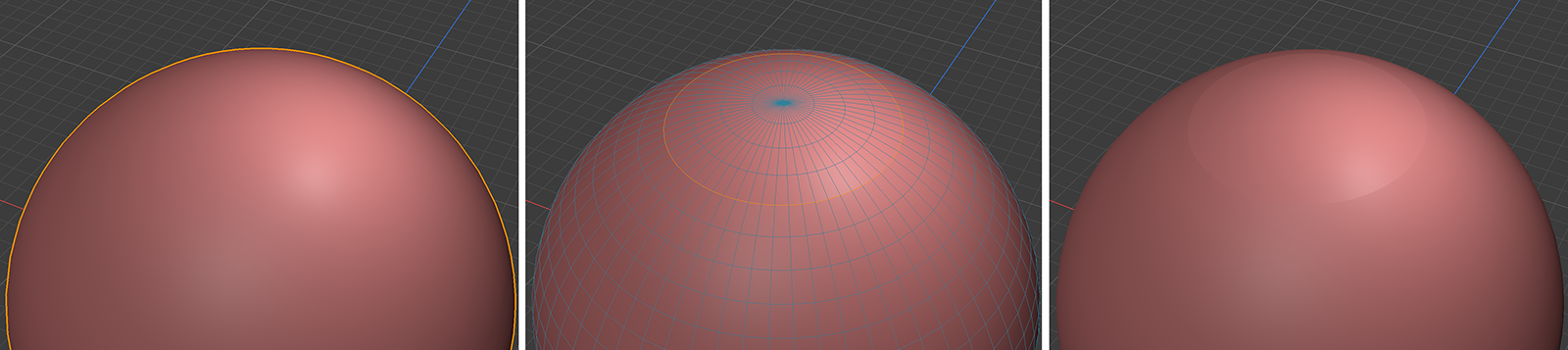 Example of the use of the Create Shading Break command. The effect can be reversed again by using Smooth Shading Break.
Create Shading Break/Smooth Shading Break: The current shading can be interrupted by Create Shading Break at the selected edges (see images above). These edges will then appear hard shaded, which may be desirable especially for mechanical low polygon objects. The effect can be undone at any time by calling Smooth Shading Breaks for these edges. Edges with broken shading can also be selected automatically using the Select Shading Breaks command.
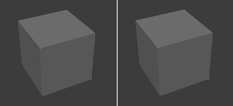
 Example of the use of the Connect command. The command can be executed several times until the desired density of new edge loops has been created.
Connect:The selected edges are divided in the middle and the resulting new points are connected. This allows you to add uniform edge loops. Since the original edge selection is automatically transferred to the split edges, the command can also be called several times in succession until the desired edge density is achieved (see figure above).
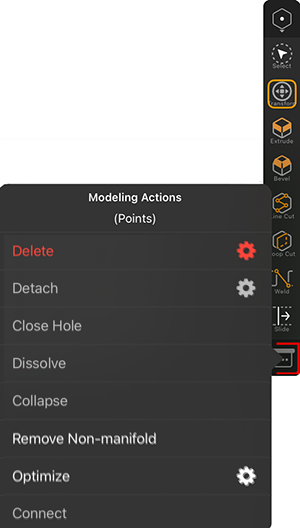
This image shows the Modeling Actions menu while in Points mode. Some of the available actions are also avilable in Edges mode and have been described already. That's why we focus on the edge specific commands and options here:
|
|
Close Hole: Having an open area that is completely surrounded by faces (and selected points), this command will close that opening with a patch of polygons that tries to keep the flow and density of the mesh. To make this work, all points along the opening have to be selected.
Dissolve: All polygons that share at least one of the selected points get combined into N-gons (see example in the image below). N-gons are faces that can be defined by more than four edges. The only drawback is that although complex and even curved surfaces can be represented by an N-gon, there are no editable points within the surface of the N-gon. Only the edges and points on the edge of the N-gon are normally editable. This limits the possibilities to shape an N-gon in all dimensions. On the positive side, however, N-gons can be selected with a single mouse click and edited with the modeling tools like normal polygons.
Collapse: All selected points are moved to the center of their group and then merged into a single point.
Remove Non-manifold: Whenever more than two polygons meet at an edge, it is a mathematically undefined surface. The command therefore splits the surface at this edge. Thus the action corresponds to using the Detach command for the non-permissible surface at the edge. To ensure that all edges of the object are checked accordingly, make sure that no point selection is active when the command is called.
Optimize: This action can be used to find and remove double or overlapping elements, such as points that are in a very short distance towards each other. Within the tools options you can set this distance with the Tolerance value. Note that this action is limited to the elements of the current selection. If you like to optimize the complete mesh, Clear any edge selection first. There are also some options available for this action:
Polygons: Polygons, that don't contribute to the visible surface (for instance, when all points are positioned on a straight line), are automatically removed.
Unused Points: Points, that are not a part of any edge or polygon are removed.
Points: Points, that are placed within a very close radius (set by the Tolerance value) are welded into a single point.
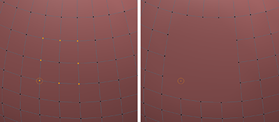
Connect:A new edge is created between the selected points of a polygon (see image below).
 Example of the use of the Connect command. The effect is comparable to a Line Cut between the two selected points.
To select Objects, Faces (polygons), Edges or Points you first select the right Edit Mode and can then use the Select Tool. Additional selection commands are also avilable in the Selection Actions menu. To find the Selection Actions in that menu you have to hold one of the modifier buttons to add or subtract selections in the Shortcurts Panel (see image below).
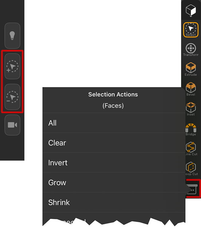 First hold one of the selection modifiers (see highlighted icons on the left side), then open the Selection Actions menu (see right side).
The following actions are available:
All: It selects all the elements in the mesh, based on the active Edit Mode.
Clear: It deselects all the elements in the mesh, based on the active Edit Mode.
Invert: It inverts the currently active selection.
Grow: The current selection grows by one element in the border area.
Shrink: The current selection is shrinking from its edges.
Connected: Expands the currently visible selection to the entire area connected to the selected areas.
Convert: Any selection can be changed to another element type. For example, an edge selection can be converted to a point selection. The following options are available:
From: Here you choose the selection you want to convert. You can choose between Vertex, Edge, Polygon, UV Vertex and UV Polygon.
To: Here you select the selection to be recreated by the conversion. Also available here are the types Vertex, Edge, Polygon, UV Vertex and UV Polygon.
Tolerant: In a Tolerant conversion, the elements of which only a part was selected in the initial selection are already selected. So, for example, if only one point was selected, the tolerant conversion can select all edges or all polygons related to this point. Without tolerant conversion, for example, both start and end points of an edge would have to be selected so that this edge would also be selected during the conversion.
Symmetrize: This action can be used to mirror point, edge or polygon selections of polygonal objects based on the mesh symmetry settings.
Selection Mode:
Mirror (Add): The current selection gets mirrored and is then added to the original selection.
Mirror (Subtract): The current selection gets mirrored and is then subtracted from the original selection.
Flip: The current selection is mirrored. The original selection gets lost.
Outline: In Polygon Edit Mode, this tool selects the edges that outline the selected polygons.
Fill(in Edge mode): This selects all polygons that are surrounded by a closed edge loop selection.
Select Shading Breaks(in Edge mode): It selects all edges that have been applied with a shading break.
Path(Edge or Point mode):