
This mesh can be edited with polygonal modeling tools, which can modify its topology.
Tabel of content
When trying to use polygonal modeling tools on a primitive object, such as a Sphere, a Cube or a Cylinder, an option is displayed to convert that object to an Editable Mesh.
However, a conversion to an Editable Mesh can also be executed at any time via the corresponding icon in the parameter settings of a primitive object or via the context menu that opens by a held click on an object entry (see images below).
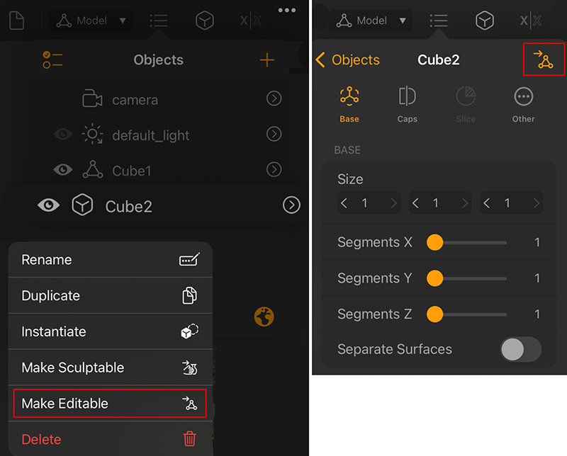 The left side shows the option to convert an object to an Editable Mesh in the objects list context menu. The right side highlights the icon for an object conversion to an Editable Mesh in the parameter settings.
Tip:
Sculpting tools can also be used on an Editable Mesh, it is recommended however that any mesh over 200K faces is converted to Sculptable if the sculpting tools are to be used.
Hint:
When combining parametric primitives, you will always get an editable mesh as a result.
|
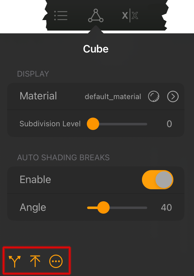
Split/Extract Submeshes...:
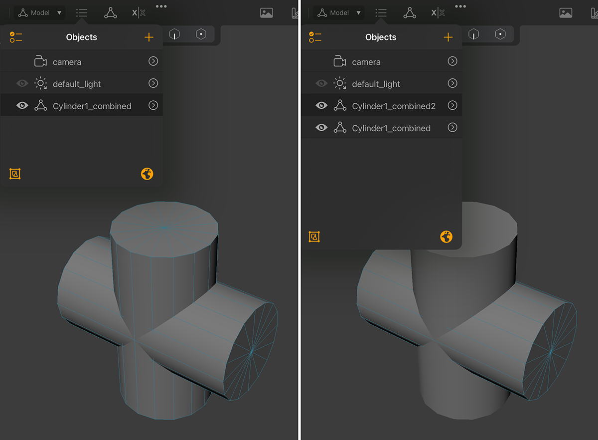 An object that consists of meshes that have no connection to each other can be divided into individual objects. The left picture shows such an object, which was created by connecting two cylinder objects. After executing Split by Submesh, the two original cylinders are visible again in the Object List. An object that consists of meshes that have no connection to each other can be divided into individual objects. The left picture shows such an object, which was created by connecting two cylinder objects. After executing Split by Submesh, the two original cylinders are visible again in the Object List.
|
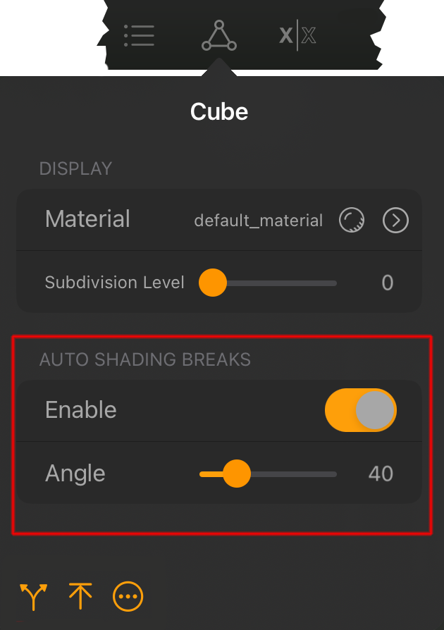
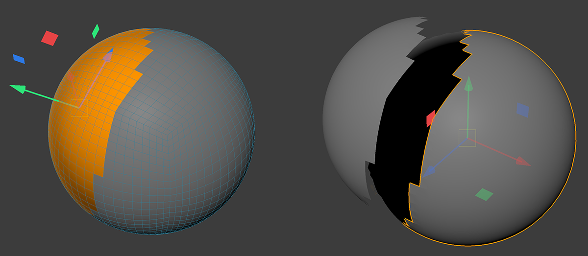 The selected polygons of an object can be separated with Split Selected Faces and made into an independent object.
 Auto Shading Breaks can be used to specify the angle up to which the shading of an edge is still soft. If the angle between two adjacent polygons is above this, the shading is interrupted there and the edge between the surfaces becomes visible.
|
Normals... :
|
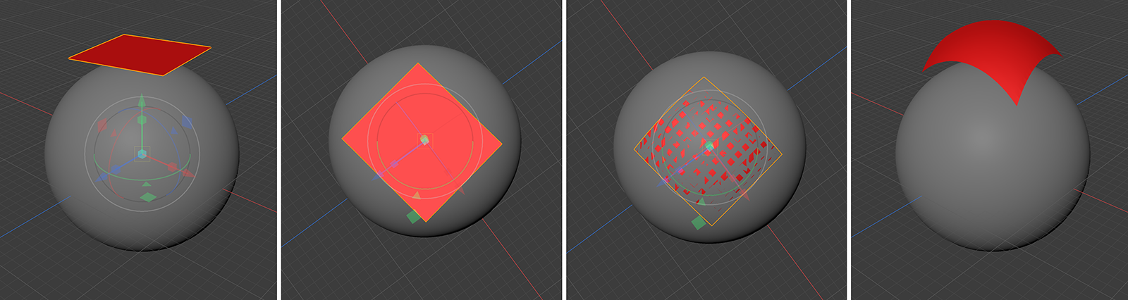 This image sequence shows a typical sequence of projection of a mesh (here a plane) onto another object (here a sphere). First, you place the object to be projected and then align the view to describe the desired projection direction. In this view, the object to be projected should lie completely over the areas of the other objects to be projected (see second image). The two images on the right side of the figure show the result, which can be seen especially after pulling away the now deformed plane (see image on the right side).
 Mesh Projection Settings:
Targets: Here you can choose whether you want to project onto all objects or only onto the objects and surfaces that are currently visible from your line of sight.
Max. Distance: This is the maximum distance that may lie between the points of the object to be projected and the other objects in the scene for a projection to be calculated.
Create Layer: This option is only relevant if you have selected a Sculptable Mesh and are projecting. In that case, the deformation of the projected object can be used as a sculpting layer and thus also weighted individually.
Symmetry: Activate this option to automatically mirror the deformation of the projected object along a selectable axis.
Symmetry Axis: The deformation of the projected object in the axis range specified here is automatically mirrored to the opposite axis side. Thus, when using -X, for example, the deformation on the negative X-axis side is mirrored on the positive X-axis side.
Symmetry Origin: Here you can choose whether the axes of the world system (World) or the axes of the projected object (Local) should be used for symmetry.
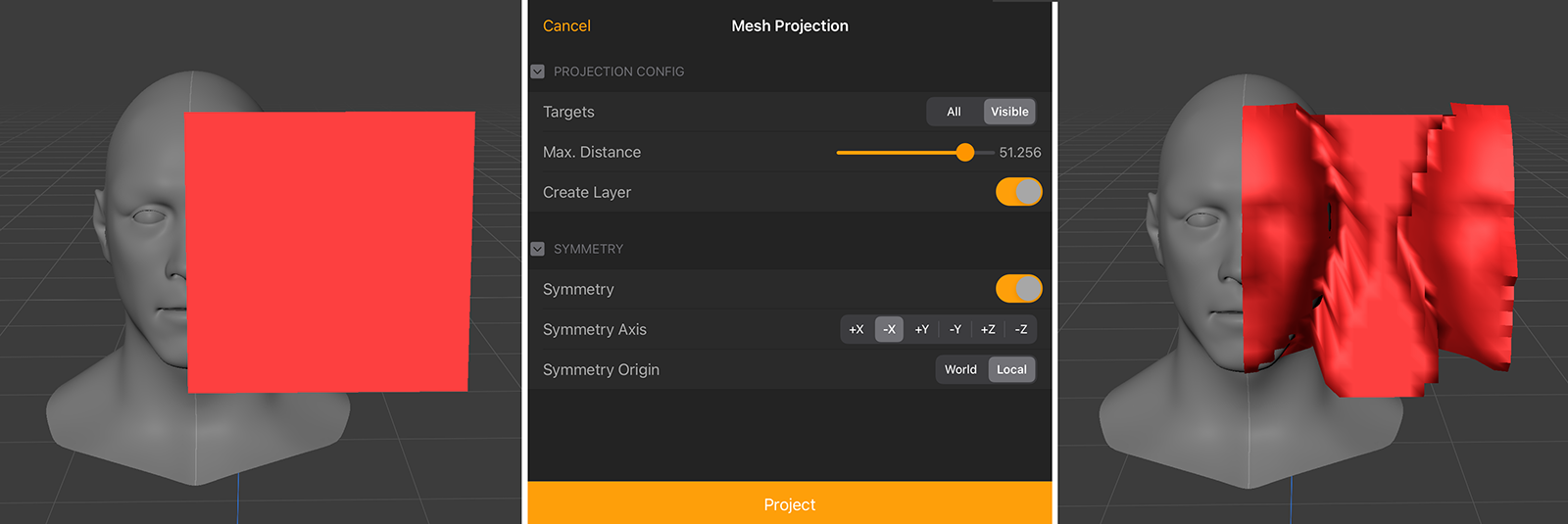
Example of a Plane Editable Mesh projected onto a head model. Since the plane hits only one side of the face, the result can be automatically mirrored on the free side of the plane by using the Symmetry function of the Mesh Projection.

When Create Layer is activated while projecting a Sculptable Mesh, a Sculpting Layer is automatically created for that shape change.
If you need a more individual way to project a Sculptable Mesh, have a look at the ZProject Brush.
Bake Transform: Applies the node transform to the mesh.
|
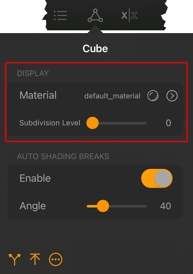
This part of the selected object settings lists the material used, allows you to select a material for this object and provides a Subdivision Surface function.
|
Subdivision Level: An Editable Mesh can have additional subdivisions that are automatically used to round off the shape as well. These subdivisions are calculated parametrically and can therefore also be reduced or increased again at any time. The original shape is therefore not changed by this.
This is a very powerful function to be able to use a relatively simple object for modeling with polygons, which can then appear very complex and organically rounded by the parametrically added subdivisions. Each time the value is increased by 1, all quadrangular polygons are subdivided once lengthwise and once crosswise. One polygon thus becomes four polygons. A further increase by 1 quarters these areas again. So there are already 16 times as many polygons compared to the original.
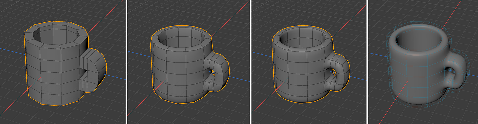 This image sequence shows a low polygon mug modeled in Forger on the left, using modeling tools on a cylinder primitive that was converted to an Editable Mesh. The second and third image shows the same mesh with 1 and 2 Subdivision Levels. The image on the right shows the same object, but this time with an active Loop Cut tool. The original mesh is visible as a blue wireframe while the rounded mesh is still visible shaded.
Important:
Take note that the added Subdivision Levels will get lost if you convert an Editable Mesh to a Sculptable Mesh!
Sculpable Meshes have their own tools to add subdivisions.
|
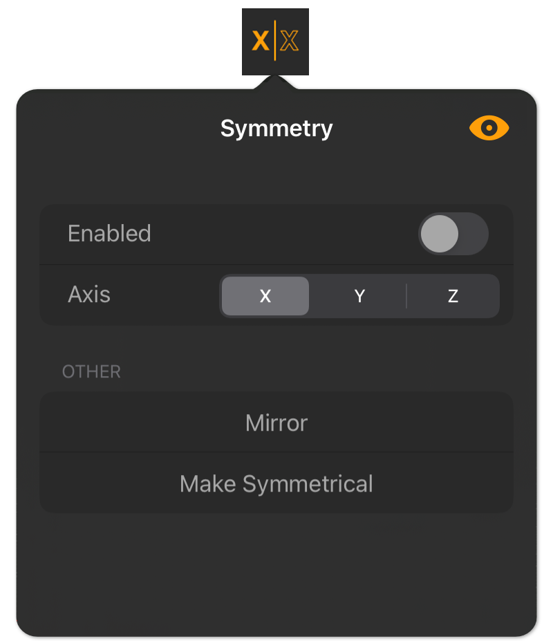
This section controls the way that Forger deals with symmetry on the selected model. Important:
|
In order to model a mesh symmetrically, choose an axis and any edits that are done on one side of the mesh will be replicated on the other side of the mesh along that axis. This assumes that the originating mesh is somewhat symmetrical. The axis directions are always oriented to the world axis system.
Use this option to switch the Symmetry on or off for the selected mesh object.
Here you select the axis direction along which the symmetry should act. If you select X, the mirror plane is therefore created between the Y and Z axes. The mirror plane is indicated by a thin line on the surface of the object. You can activate and deactivate this line with the eye symbol in the upper right corner of the Symmetry dialog.
 The bright line indicates the chosen plane of symmetry and always runs through the origin of the world axis system.
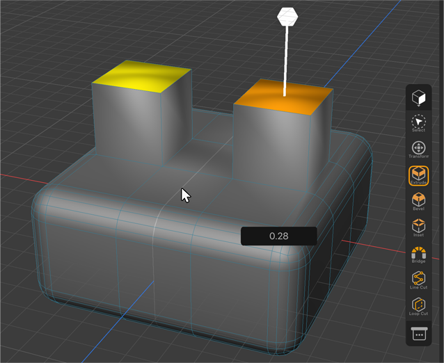
As you can see on the image above, any selection or modeling that is performed on one side of the selected symmetry happens automatically on the other side. In this example, a surface was selected on the right side of the cube and then extruded. As you can imagine, this works best with objects that are still original, i.e. aligned along the world axes. For rotated or asymmetrical shapes, the Symmetry function tries to find elements on the mirrored side that are as close as possible to the elements of the other side. The following figure also shows an example.
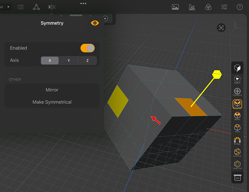 The red arrow points to the symmetry plane along the world x axis. The polygon selection on the right is mirrored to the closest element on the left.
This command flops the current mesh across a given user-specified axis.
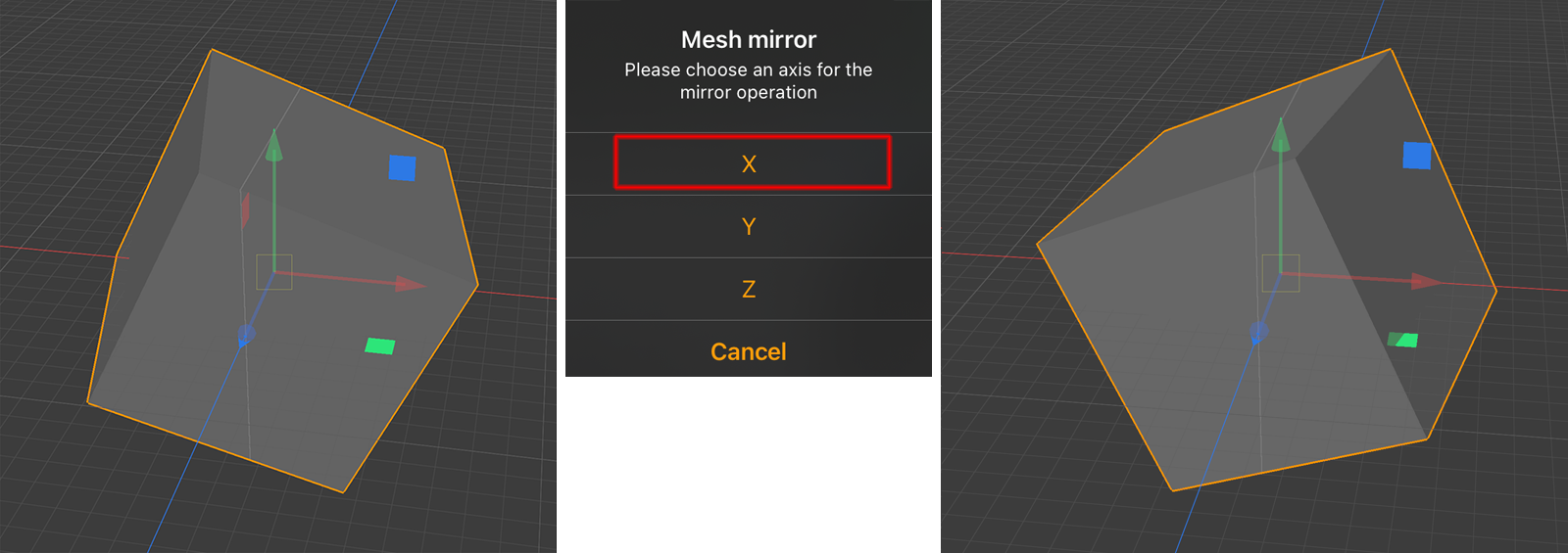 The original cube mesh is seen on the left side. The result after using Mirror X is seen on the right side.
This feature allows users to forcefully make a mesh symmetrical, it will internally slice, duplicate, mirror and merge the two halves. Note that there may be cases where this action cannot be performed. This can be the case, for example, for meshes with a lot of polygons, when too many points are very close to the symmetry plane.
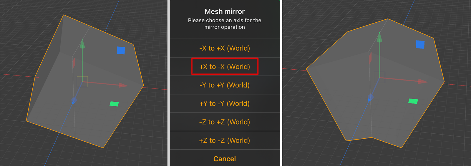 The original cube mesh is seen on the left side. The result after using Make Symmetrical with +X to -X (World) is seen on the right side.