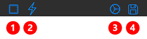
This menu shows tweakable parameters for the active tool. You can change the active tool from your SideBar shortcut buttons or the tool picker, also found in the SideBar.
Every tool in Forger has a different set of parameters, and each parameter within a tool will change the way this tool behaves when applied to the target mesh (or canvas).
There is a tool preview at the top of the Tool panel (only applies to brushes), so you can get quick feedback about how a parameter may affect the active brush visually, by tweaking it and having a look at the refreshed preview.
This tool allows applying various types of transformations to the selected mesh. It can be used to Translate, Rotate and Scale the mesh The tool "mode" can be changed by pressing the different Universal/Translate/Rotate/Scale buttons on the sidebar. The tool offers different handle representations depending on the transformation mode that the tool is in.
You can also offset the pivot by holding the Pivot shortcut button in the Shortcuts Panel on the left.
The following options are available for this tool:
Snap Alignment: Choose the axis system for the orientation of the Transform when snapping to the mesh.
Normal: Oriented along the surface normal
View: Oriented along the current viewing direction
To enable snapping of the Pivot to the surface of the Sculptable Mesh the Masking modifier must be held and a small dragging motion must be performed over the desired location on the surface. On the left you can see the orientation along the surface normal, on the right the orientation in the viewing direction.
Ignore Symmetry:If a symmetry is active, you can select here whether it should also apply to the transformation or not. The following figure illustrates this with an example.
On the left is the original Sculpting Mesh, for which symmetry along the X axis is active. A soft masking of the snout and the forhead has been applied to it so that only the ears are moved. With Ignore Symmetry turned off, the active symmetry is taken into account and when rotating, both ears move outwards (see image in the middle). If Ignore Symmetry is off, both ears are rotated in the same direction (see image on the right).
Invert Transform: Moves and rotates the Pivot system to align it with the World system. This will move the mesh with it.
Center Selection: Centers the pivot system in the currently selected mesh.
Center Masked: Centers the pivot system within the currently masked areas.
Center Unmasked: Centers the pivot system within the currently unmasked areas.
Universal
Contains all three manipulators, described below.
Translation
Moving the central handle: Moves the element freely, according to the direction of movement.
Pulling on an axis handle: Moves only along the chosen axis direction.
Moving the red, green or blue rectangular handles: Allows you to move freely, but locks the axis direction with the color of the tapped rectangle.
Rotate
Drag on the area of the object, inside the red, green and blue rings: Rotates the element freely.
Touching and pulling the red, green or blue ring: Rotates only along the chosen ring direction.
Touching and pulling the gray ring: Rotate around the current viewing direction.
Scale
Moving the central handle: Scales the element freely and evenly along all directions.
Pulling on an axis handle: Scales only along the chosen axis direction.
Moving the red, green or blue triangular handles: Allows you to scale freely, but locks the axis direction with the color of the tapped triangle.
Mirror
This mirrors the pivot point of the currently selected Transform function along the current symmetry direction. This is especially helpful if the pivot point has been moved manually and is therefore no longer central in the object.
Using the Transform Tool for masking
The Transform Tool settings (or the settings of any other sculpting brush) also allow to choose between several geometric shapes that can be used for masking. To apply the masking, just hold down the Mask Modifier button in the Shortcuts Panel and start to draw from outside of the object. So the first tap has to be in the empty viewport.
You can choose between Rectangle, Square, Ellipse, Circle and Lasso
First open the Transform Tools settings and choose the shape you like to use for masking (see number 1). Next hold down the Mask Modifier button (see number 2) and start to draw from a position outside of the active mesh (see number 3) to create the mask.
There are also additional actions available to work with maskes directly from the Transform Tool:
You can also use the same technique to delete all maskes from the active mesh. Just draw a masking shape completely outside the selected mesh while holding th Mask Modifier.
Holding the Mask Modifier and simply tapping the empty viewport inverts the existing mask.
By holding the Mask Modifier and the Pivot Modifier buttons together and drawing a masking shape, you can subtract that drawn shape from an existing mask.
Holding the Mask Modifier and simply tapping the mesh will blur existing masks.
Holding the Mask Modifier and the Pivot Modifier together while tapping on the mesh will sharpen existing masks.
Holding the Mask Modifier and the Smooth Modifier shortcuts together allows you to draw the chosen masking shape, starting from outside of the mesh. This time the unselected area of the mesh will be hidden in the viewport.
Holding the Mask Modifier, the Smooth Modifier and the Pivot Modifier at the same time, you can draw a selection shape (start to draw outside of the mesh). This time only the mesh area that is inside the drawn shape stays visible. All other mesh parts get hidden in the Viewport.
Sculpting Tools
Forger comes with various different brushes. Each brush has two different modes, a normal and an "alternate" mode; the "alternate" mode can be triggered by pressing the +- Shortcut button found in the left sidebar in sculpting context (see icon on the left).
A tools behavior will change depending on whether it is running in "regular" or "alternate" mode.
Holding down this Smooth Modifier button while using any Sculpting Tool will switch to a Smoothing brush. This way you can smooth you sculpted details at any time without having to switch tools.
This Modifier will only be available when using the Vertex Color Brush. Holding down this Eyedropper Modifier button while using the Color Brush allow to pick up color values from the surface of the active Sculptable Mesh.
Generic Brush Parameters
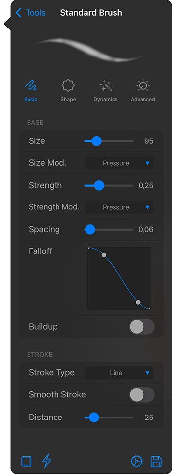
Basic Settings > Base Settings
Size: Size of the brush
Size Modifier: Determines how the size of the brush can be modified during use of the brush.
None: The size is constant
Pressure: The size is pressure-dependent
Strength: Strength of the brush (in screen space units)
Strength Modifier: Determines how the flow of the brush will vary.
None: The strength is constant.
Pressure: The strength is pressure-dependent
Spacing: defines the minimum distance between two consecutive dabs of the brush in the same stroke (in brush size units 1.0 = brush size).
Falloff: This curve describes the intensities of the brush tip starting from the center (left edge of the curve) to the outer area of the brush (right edge of the curve).
Buildup: Without this option, an uninterrupted brush stroke can only deform the surface by a maximum of 100%. With this option active, the Strength used is added up if an area is painted over several times with an uninterrupted brush stroke. This can then quickly lead to deformations that go far beyond 100%.
Basic Settings > Stroke Settings
Stroke Type:
Dabbing: Each sample of the brush stroke will be evaluated as a dab (dot) at the input coordinates.
Line: Between each sample of the brush stroke, Forger will fill in with as many dabs as necessary (considering the brushes spacing), making strokes look as continuous lines.
Smooth Stroke: Defines whether smooth stroke is enabled or not. This function makes the brush look as if it is being pulled behind on a leash (see Distance value), which automatically compensates for minor jitters or swings in the brush stroke.
Distance: Distance in screen space units at which the brush stroke will take effect, any distance smaller than this will be ignored, this parameter is used to make smooth lines and curves removing unwanted jitters (only available with Stroke Type: Line).
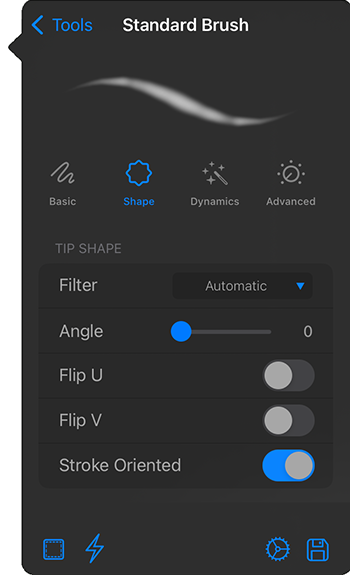
Shape Settings > Tip Shape
Filter: Filtering applied to the tip image.
Angle: the initial angle of the tip image to use.
Tip Flip U: flips the tip image on the X-axis.
Tip Flip V: flips the tip image on the Y-axis.
Stroke Oriented: Aligns the tip image to the stroke, making it follow it.
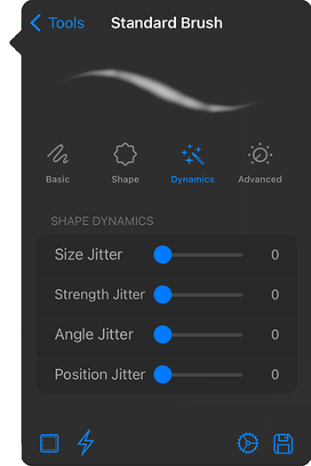
Dynamics Settings > Shape Dynamics
Size Jitter: Adds a certain randomness to the brush Size.
Strength Jitter: Adds a certain randomness to the Strength of the brush.
Angle Jitter: Adds a certain randomness to the brush tip Angle.
Position Jitter:This adds a random deviation to the path of the brush stroke.
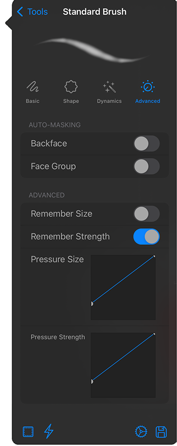
Advanced Settings > Auto-Masking
Backface:You can use painting and sculpting brushes on the backside of faces.
Face Group: The current brush can only modify the Face Group on which its brush stroke was started. Groups can be created, for example, from a Mask (Modify Groups > Group Masked). To visualize Groups in the viewport, activate Colors Group from the Display Settings (Basic tab).
Advanced Settings > Advanced
Remember Size: When switching back and forth between the different Sculpting Brushes, the last used Size of each brush is always set automatically.
Remember Strength: When switching back and forth between the different Sculpting Brushes, the last used Strength of each brush is always set automatically.
Pressure Size: This curve describes the multiplier used to control Size when using Size Modificator: Pressure. The left edge of the curve shows the multiplier for low pressure and the right edge shows the multiplier for high pressure.
Pressure Strength: This curve describes the multiplier used to control Strength when using Strength Modificator: Pressure. The left edge of the curve shows the multiplier for low pressure and the right edge shows the multiplier for high pressure.
Brush Actions
Area Selection: When holding down the Mask Modifier button in the left Sidebar and starting your Brush stroke outside of the mesh, you can directly create a Mask without having to switch tools. You can chosse between a Rectangle, a Square, an Ellipse, a Circle or a Lasso selection to create a masked area.
Choose between different search types to find the Sculptable Mesh below the tool when sculpting.
Here you can revert all tool current settings to their default values.
This opens a dialog to save the current tool settings as a Preset for easy access in other projects.
Standard
Regular: Pushes vertices in the direction of the average normal.
Alternate: Pushes vertices in the opposite direction of the area normal.
Clay
Regular: Moves vertices with a nice clay-like effect, filling holes and building up in the direction of the average normal.
Alternate: Works in the opposite direction of the area normal.
Move
Regular: Moves vertices in screen coordinates from the starting coords.
Alternate: Pushes vertices along the area normal from the starting coords.
Flatten
Regular: Pushes vertices over the average plane defined by the average point position of the affected vertices and the area normal.
Alternate: Same effect.
Layer
Regular: Pushes vertices up to a per stroke limit in the direction of the area normal.
Alternate: Works in the opposite direction of the area normal.
Inflate
Regular: Pushes vertices in the direction of their own normal.
Alternate: Works in the opposite direction.
Pinch
Regular: Pushes affected vertices closer to the center of the stroke.
Alternate: Pushes vertices away from the center of the stroke.
Smooth
Regular: Averages the position of the affected vertices with their adjacent ones. This brush is heavily affected by the density of the mesh area(s) where the brush is acting upon. To increase smoothing, activate the lowest possible subdivision level of the mesh. You can use the Smooth Brush at any time by holding the Smooth Modifier Shortcut while having any other brush tool selected. This makes it possible to quickly switch between a sculpting function and subsequent smoothing.
Alternate: Same effect.
Crease
Regular:This can be used to form grooves and other hard countersinks.
Alternate:Hard defined ridges are formed.
Scrape
Regular: Pushes vertices onto the average plane defined by the positions of the affected vertices and the area normal.
Alternate: Same effect.
Polish
Regular:This tool is used to remove material. The effect is stronger in areas with slopes than in flat areas.
Alternate:Lowered areas are filled in. The effect is thus partly similar to filling a mold with sand.
Planar
Regular:When tapping the surface, an averaged surface normal is calculated at this point. A plane is created perpendicular to this. This tool is less suitable for painting than for leveling the immediate area under the first tapped point.
Alternate:The area tapped first remains unchanged. Instead, the surrounding area aligns and forms a plane.
Pull
Regular: Moves vertices in screen coordinates.
Alternate: Pushes vertices along the area normal.
Stamp
Regular: Pushes vertices along the avergage normal or the VDM normal based on the stamp you have selected in the stamp picker.
Alternate: Works in the opposite direction.
Using and creating Brush Tips
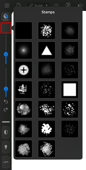
Forger already comes with a selection of useful brush tips that you can use for all sculpting and painting tools via the Stamp Selection icon (see red highlighted area to open the Stamps selection). Without choosing one of the Stamps there, the standard round brush tip is always used by default.
However, you can also add any of your own brush tips by loading square black and white images into Forger's corresponding Stamps folder.
But even if no external sources for brush tips are available, new brush tips can be created directly with Forger. You will already find a Stamp Template in the selection list for new objects in the Objects List. It is a simple square plane intended for painting with the Vertex Color Brush.
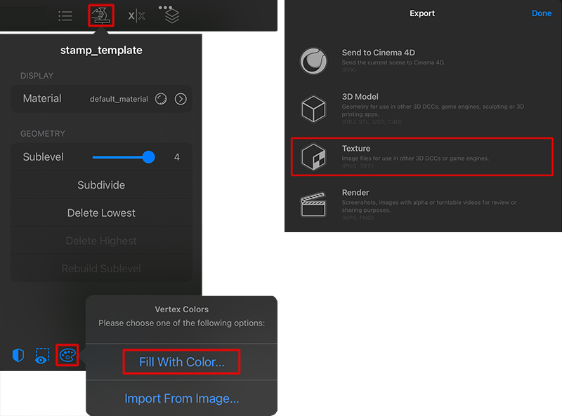
Brush tips usually use black as the base color and only the areas that are actually to be used as brush tips are drawn lighter. It therefore makes sense to first color the entire plane black after selecting the Vertex Color Brush. The fastest way to do this is to use the Fill With Color... command, which you can access directly via the Sculptable Mesh settings, for example. After that just choose white as a color and start to draw on the plane with the Vertex Color Brush.
When you are done painting, open the Export dialog and select Export Textures there. Select the painted Stamp Template object for export and leave only the Vertex Color export options active. This will create a simple image file that you will need to place in the stamps folder of your Forger installation. From now on, your new brush tip will be available with every Sculpting Brush. The following images document this workflow again.
First add the Stamp Template to the project, then fill the surface with black color and start painting with white color by using the Vertex Color Brush. When you're done, choose the Export command from the File menu and select the Texture option.
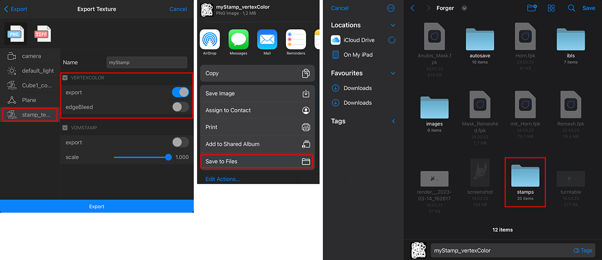
Select the Stamp Template in the list on the left for the texture export and be sure to have the 'Export' option for VERTEXCOLOR active. Choose the 'Save to Files' option and select the 'stamps' folder in the Forger directory. Enter a meaningfull name and then use the 'Save' command in the upper right corner of the dialog.
Relax
Regular: Evens out the positions of the vertices while keeping the surface forms.
Alternate: Same effect.
Mask
Regular: Marks affected vertices as masked, all brushes will have less or no effect on masked areas.
Alternate: unmasks affected areas.
There are also several gestures and other masking options available. You can find them documented here. There are also additional masking commands available from the Radial Menu or the settings of a sculptable mesh. Here you can read more about that.
Color
Regular: Allows applying vertex colors onto the mesh.
Alternate: Activates the Eye dropper to pick up a color from an already painted part of the surface.
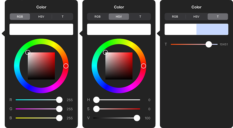
The Color Chooser
Here you can see the three different options of the color chooser to set a color. The RGB system uses red, green and blue color components to describe a color value. The HSV system, on the other hand, is more intuitive to use, since here only one value can already be used to select the desired color (H value). The S value stands for the saturation of this color and the V value for its brightness. The third color system uses color temperatures. This can be helpful, for example, for setting a light color. Warm colors have small T-values, cool colors are defined by higher values. Since this system is based on the colors that can also be observed, for example, when metals are heated, only colors between red, orange, white and light blue can be set.
ZRemesher
This allows the topology and polygon density/polygon count of a Sculptable Mesh to be customized. The functions here go far beyond those of the Remeshing function, which can be found in the mesh settings.
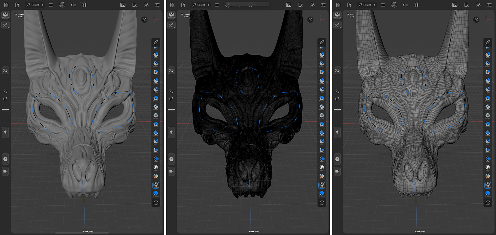
Integrated painting tools can be used to paint paths on which the polygon flow of the mesh restructuring is oriented. The resulting polygon density can also be controlled by using vertex colors. The following image gives an example.
The image on the left shows the original mesh that was imported and has no subdivision layers. It already shows the topology curves painted on the surface that will guide the ZRemesher in restoring the topology with a much lower polygon count. The image in the middle shows the original mesh density. The image on the right shows the final mesh after it has been recreated with ZRemesh.
The ZRemesher treats each mesh surface individually and therefore does not, for example, create fusions between adjacent structures that have been created, for example, by using the Connect command in the Objects List.
If you're looking for a shape restructure feature that also involves merging nearby shapes, check out the Remesh command istead.
Lets have a look at the available options:
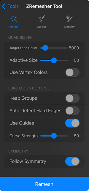
Quad Sizing
Target Face Count: Here you can define the absolute number of polygons to be created. Note that this is a target value, which may not be reached, i.e., the actual number of polygons will lie near this value. Adaptive Size and Use Vertex Colors options will increase the resulting polygon count further.
Adaptive Size: Normally, remeshing is performed using polygons of approximately the same size. This can result in loss of definition, especially in areas with sharp changes of direction and fine details. To counteract this effect, the polygon size can be automatically reduced in these areas and also deviate more individually from the perfect square shape of polygons. The higher this value is set, the more freedom the algorithm has in scaling and shaping the polygons. Note, however, that with higher values the generated polygon count can also increase far beyond the Target Face Count.
Use Vertex Colors: By activating this option, the polygon density can be increased or decreased individually by using the vertex color red and cyan. Areas painted red automatically get smaller polygons and can thus better preserve existing details. Areas, that have been colored in cyan, will have a reduced polygon density (fewer and larger polygons). To do this, you will find a Density Brush directly on the ZRemesher tool, which automatically paints with red or cyan colors. But you can also apply these vertex colors with the standard Vertex Color Brush before using the ZRemesher. This is as well recognized by the ZRemesher. With Use Vertex Colors all vertex colors are removed from the mesh after the ZRemesher calculated the new mesh. Controlling the polygon density by Vertex Colors always changes the total number of polygons. The specified number of polygons (Target Face Count) is therefore exceeded or undercut according to the vertex colors used.
Edge Loops Control
Keep Groups: Existing Face / Polygon groups are preserved.
Auto-detect Hard Edges: For models of a technical nature, many hard edges are used. These are very important for defining contours. Activating this option helps to preserve these details, as angle divergences are used to automatically determine what should be detected as a hard edge.
Use Guides: The ZRemesher Tool also provides a drawing tool for curves. By drawing curves directly on the surface, you can control the resulting edge flow of the mesh. Note, however, that the edge flow cannot always follow these curves perfectly, but only as closely as the algorithm or the existing shape allows. Also note that the ZRemesher algorithm is already able to analyze the structure of a surface and create matching edge loops without the additional guides. Painted curves can nevertheless be helpful whenever this automatic recognition of shapes fails or should be changed individually. The following image gives an example.
Curve Strength: This controls the influence of the guides on the calculation. This is only relevant if Use Guides is active.
Symmetry
Follow Symmetry: If your Sculptable Mesh was created with Symmetry, you should leave this option checked so that this symmetry along the active axis direction is maintained at the new topology.
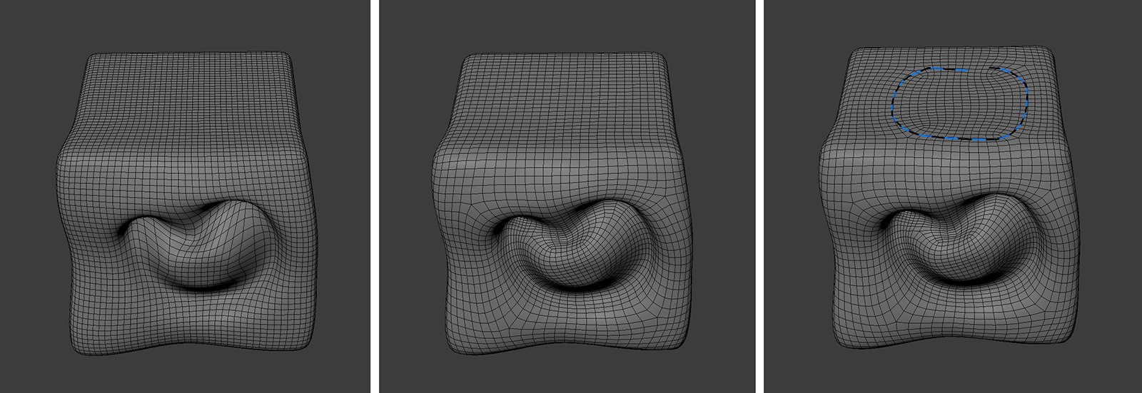
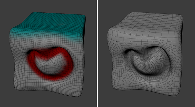
The effect of topology control will be illustrated by this very simple example. On the left is a slightly deformed cube. In the middle you can see the result of the ZRemesher tool, without the use of guides. The tool automatically recognized the details on the front of the cube and created corresponding loops there. On the right, a circular guide was painted on the top of the cube before the ZRemesher was executed. After running the ZRemesher (again using the mesh from the left image as the source, an additional loop structure is created in this area, which can be useful, for example, for subsequent deformations.
Painting ZRemesher Guides
Drawing and using Guides for the ZRemesher is very simple:
Activate Guide drawing: First you have to choose the drawing mode for Guides from the icon marked with the number 1. This allows you to directly draw a curve on the surface of the mesh. There is no option to close that guide curve, but if the starting and ending points of a guide are close enough, it will be considered as a closed loop during the ZRemesher calculation.
You can draw as many guides as you like and you can also use Symmetry to draw them.
The direction of drawing a guide doesn't matter (clockwise or anti-clockwise).
To clear the existing guides, use the Delete Guide icon on the left and draw over the guide that should be removed or choose the Clear Guides button directly from the ZRemesher Tool settings to remove all guides at once (see number 2).
To use the drawn guides you have to take care that the Use Guides option is active in the ZRemesher Tool settings (see Remesh tab). There you sill also find the Remesh command at the bottom to start the process.
The Curve Strength parameter can be used to increase or decrease the importance of the guides during the calculation (see ZRemesher Tool settings, Remesh tab).
Painting ZRemesher Densities
How to use Vertex Colors to control the density of the resulting mesh:
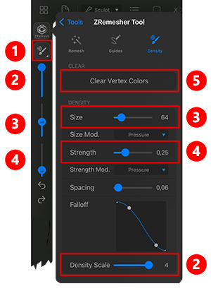
Activate Vertex Color painting: The most convenient option to paint vertex colors for density control is to use the painting tool provided directly by ZRemesher. You will find all relevant options to specify the desired brush size or polygon density. To do this, activate the Density painting mode directly via the icon at the number 1.
Choose the new Density Scale: Before you start painting, you must select how you want the polygon density to change as a result of painting. To do this, you can use a slider directly in the left toolbar (see number 2), as well as a value in the ZRemesher settings (Density tab, see number 2). The value 0.25 means, for example, that the resulting polygon density will be only 25% of the average polygon density that you set mainly via the Target Face Count. With a value of 2, the polygon density would be e.g. 200%, i.e. twice as high as in the unpainted area.
While painting, you will notice that colors between red (higher polygon density) and cyan (lower polygon density) are automatically used so that you can directly see already painted areas and their effect on the calculation.
If you have previously painted the mesh with vertex colors and Use Vertex Colors has been enabled in the ZRemesher Tool settings, these colors will also be automatically used to control the polygon density. Here, too, an evaluation is made according to red and cyan areas. Please note that the Use Vertex Colors option automatically removes all vertex colors from the mesh after the ZRemesher calculation is complete. If you want to preserve the vertex colors of a mesh, you should therefore leave this option switched off. This is because the ZRemesher is able to transfer existing vertex colors to the target mesh as well.
As with the standard Color brush, the Size and Strength of the Density Brush can be used. You can find the Size slider at number 3 and the Strength slider at number 4.
Clicking on Clear Vertex Colors in the Density settings of the ZRemesher Tool deletes all Vertex Colors from the mesh.
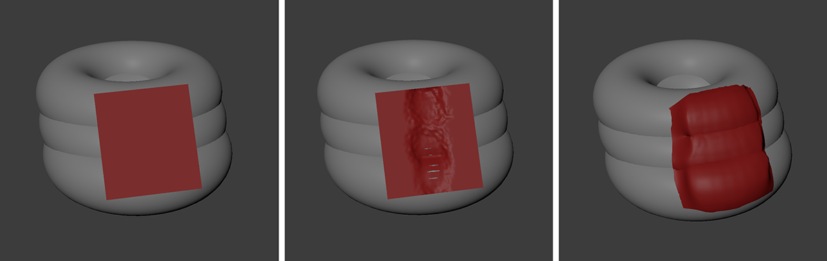
Here again a conceivably simple mesh that is to be adjusted in the resulting polygon density by painting on vertex colors. The original mesh is shown on the left. The area at the front was marked to increase the polygon density, the upper part of the cube was painted to reduce the polygon density. The result is seen on the right.
ZProject
Similar to the Mesh Projection feauture , the ZProject Brush allows to project one mesh onto another. Instead of just projecting the entire mesh, you can choose which parts to project here by painting on them. This allows to choose any brush tip and to change the perspective during the process.
Because ZProject works like a Sculpting Brush, you can use any brush tips and change the perspective at any time, for example, to project a plane section by section from different directions onto a complexly deformed mesh.
Sketch Mesh
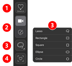
The Sketch Mesh Tool provides an easy-to-use modeling tool to very quickly design basic three-dimensional shapes that can then be refined with the other sculpting tools. With the Sketch Mesh Tool you can use the classic selection tools, such as Lasso, Circle or Rectangle, to draw the outer edges of the desired shape. The interior of this selection is then automatically filled with a volume of polygons. The tool offers these settings and options in the left Toolbar:
Here you open the Sketch Mesh Tool Settings. This tool ist not interactive with these parameters, so you have to adjust these values before you start drawing.
In this section you can switch between the Drawing mode (used to sketch geometry) and the Camera mode (used for navigation in the viewport without having to leave the tool).
Use this icon to choose between the selection tools. The Lasso selection is the most useful for drawing organic shapes, while the other selection methods are also suitable for sketching the outlines of technical objects. Take note that all selections can be used together with the + and - selection modifier keys.
A tap on this Align Camera icon adjusts the viewing direction in the viewport to the currently selected Sketch Object. This allows you to add or subtract additional selections from this shape.
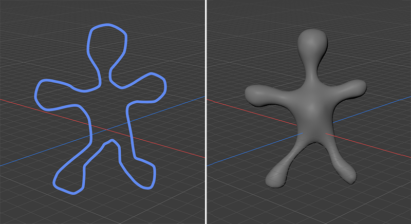
The following image give an idea of the general workflow. After activating the Sketch Mesh Tool, take care to activate its Drawing mode and choose one of the selection options in the left Toolbar (see number 3 in the image above). Start drawing the outline of the desired shape in the viewport. This is demonstrated on the left of the following image. After releasing the selection tool, a mesh filling the selection shape is created (see right side of the next image).
The left shows the outline of the needed shape, created with the Lasso selection option of the Sketch Mesh Tool. The right side shows the resulting geometry.
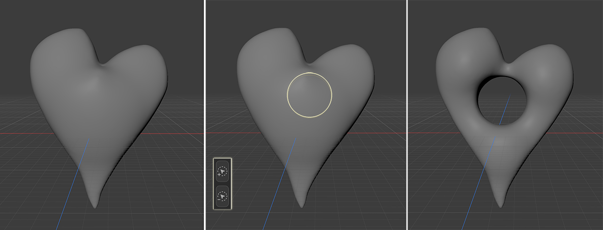
Some shapes might not be able to be drawn in one step. To overcome this limitation, additional selection shapes can be added or subtracted to an already existing Sketch. Just follow along these steps:
Take care that the Sketch Object is selected and activate the Sketch Mesh Tool.
Tap on the Align Camera icon to adjust the camera perspective to the orientation of the selected Sketch Object. This is only needed if the camera has been moved since that Sketch Object has been created.
Activate the Drawing mode of the tool and choose one of the selection methods.
Hold the +Selection Modifier to add a shape to the Sketch Object or hold the -Selection Modifier to subtract a shape while drawing your selections.
Drawing a new selection shape whithout holding one of the Selection Modifiers will always create a new Sketch Object that will not interact with other Sketch shapes in your project.
The left side shows a shape drawn with the Lasso tool. After this Sketch Mesh is created, we select the Circle Selection tool, hold down the - modifier and draw a circular selection in the center of the heart shape. This will subtract the circle from the Sketch.
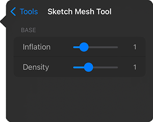
The Sketch Mesh Tool
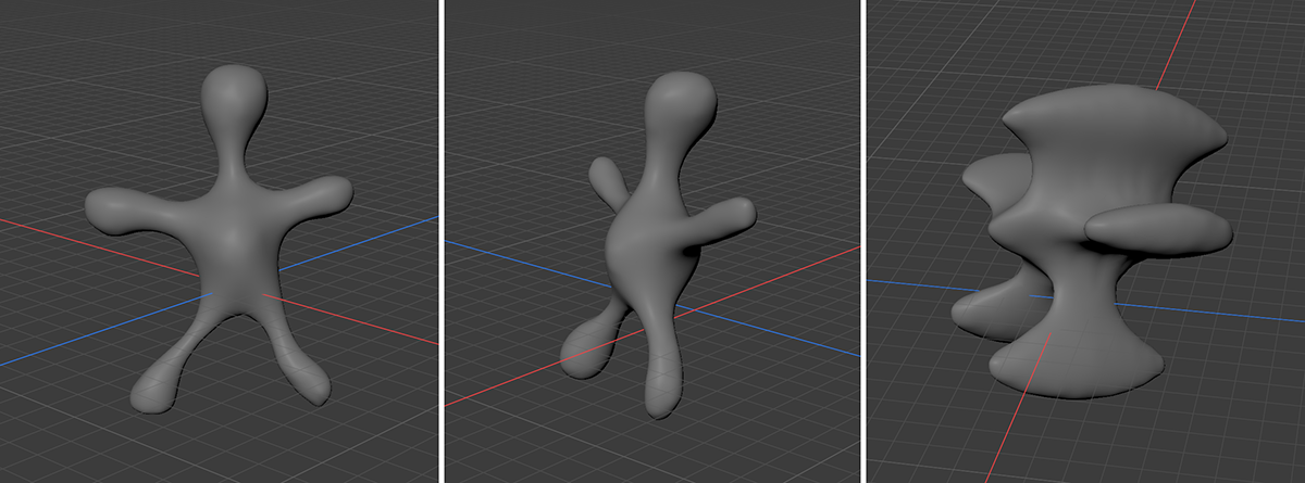
Inflation controls the thickness of the created mesh. In general, smaller areas are calculated to be less thick and larger areas are given a greater thickness. In addition, the thickness of the geometry generally decreases at the edges.The image below gives an example.
Density sets the density of polygons used to create the mesh.
On the left you can see the shape created with the Lasso tool and an Inflation of 1. The middle illustration shows this object in a side perspective. On the right is a similar shape, but with an Inflation of 3. This makes the object appear correspondingly thickened, even though the shape drawn is identical.