This menu shows tweakable parameters for the active tool. You can change the active tool from your Sidebar shortcut buttons or the tool picker, also found in the Sidebar.
Every tool in Forger has a different set of parameters, and each parameter within a tool will change the way this tool behaves when applied to the target mesh (or canvas). The example on the left show an active Transform tool, marked red. Clicking on that button brings up the individual tool settings.
Additional options and settings of the active tool will show up below the active tool icon. In this example the Transform tool can be used specific just to Move, Rotate and to Scale. Some tools also offer additional modifier shortcuts that can be found in the lower half of that Sidebar menu. These can activate a different tool behaviour without the need to open up the tool's settings.
Editable Meshes can be edited on different levels, on Object level (e.g. to move or rotate the whole object), on Polygon (Face), Edge or Point level (to use modeling functions).
The Edit Mode can be switched with the icons at the top of the viewport or by opening a drop down menu from the edit mode selector icon found at the top of the Toolbox, which is located on the right side of the viewport by default.
Take note that the behaviour and the available options of a selected modeling tool might change in regards to the active Edit Mode.
Modeling Tools
Some tools allow setting specific values by using a numeric pad, after an action starts, if the result of this action can be set explicitly a numeric input widget will appear; to set a specific value, tap on this numeric pad and enter the value you want. In most cases, further options and value inputs are also available in the respective tool settings. Note that not all tools support all Edit Modes, and that for certain effects, a selection of points, edges or polygons should be created before using a tool.
Select
Allows you to select the object or the elements (faces (polygons), edges, points) that you want to modify.
There are two modes: Pixel (with it, you can select a face/edge/point one by one) and Brush (it selects faces/edges/points working like a brush). And you can choose the type of selection that better adjusts to your workflow. Using the modifier buttons in the Shortcuts Panel on the left, you can also add or subtract elements from an existing selection. You can find all information about the available selection methods and options here.
Transform
This tool allows applying various types of transformations to the selected mesh. It can be used to Translate, Rotate and Scale a mesh or parts of a mesh (if used with a selection of points, edges or polygons). The tool "mode" can be changed by pressing the different Universal/Translate/Rotate/Scale buttons on the sidebar.
You can offset the pivot by pressing the "Pivot" shortcut button. The pivot can also be snapped to the geometry by using the "Pivot" shortcut, found in the Shortcuts Panel. Different handle representations will be drawn depending on the transformation mode that the tool is in.
Example of Universal Transform Pivot repositioning. On the left you can see the original object. By default, the Transform system is always located in the center of an object. However, by holding the Pivot button, the Transform system can also be moved or rotated as desired. Likewise, by holding the Pivot button and tapping a surface, edge or point, the pivot system can also be snapped to elements of the surface (see middle illustration). To center the pivot system again, simply tap the object (avoid elements of the Transform gizmo) without holding the Pivot button.
When working with polygon, edge or point selections, the Transform Tool can be oriented along the surface Normals of the selection (see left image) or along the fixed axis directions of the World system (see right image).
Universal
Contains all three manipulators, described below.
Translation
Moving the central handle: Moves the element freely, according to the direction of movement.
Pulling on an axis handle: Moves only along the chosen axis direction.
Moving the red, green or blue rectangular handles: Allows you to move freely, but locks the axis direction with the color of the tapped rectangle.
Rotate
Drag on the area of the object, inside the red, green and blue rings: Rotates the element freely.
Touching and pulling the red, green or blue ring: Rotates only along the chosen ring direction.
Touching and pulling the gray ring: Rotate around the current viewing direction.
Scale
Moving the central handle: Scales the element freely and evenly along all directions.
Pulling on an axis handle: Scales only along the chosen axis direction.
Moving the red, green or blue triangular handles: Allows you to scale freely, but locks the axis direction with the color of the tapped triangle.
Insert Mesh
This tool is only available in Object mode and allows to create new parameteric objects (like Spheres, Cubes or Cylinders) on the surface of any other object in your viewport. You can even use any already existing mesh and clone copies of it on an surface. To draw the new object, just tap and drag on any surface in the viewport to place, scale and rotate the new object in one step. With any additional tap-drag-action a new object will be created.
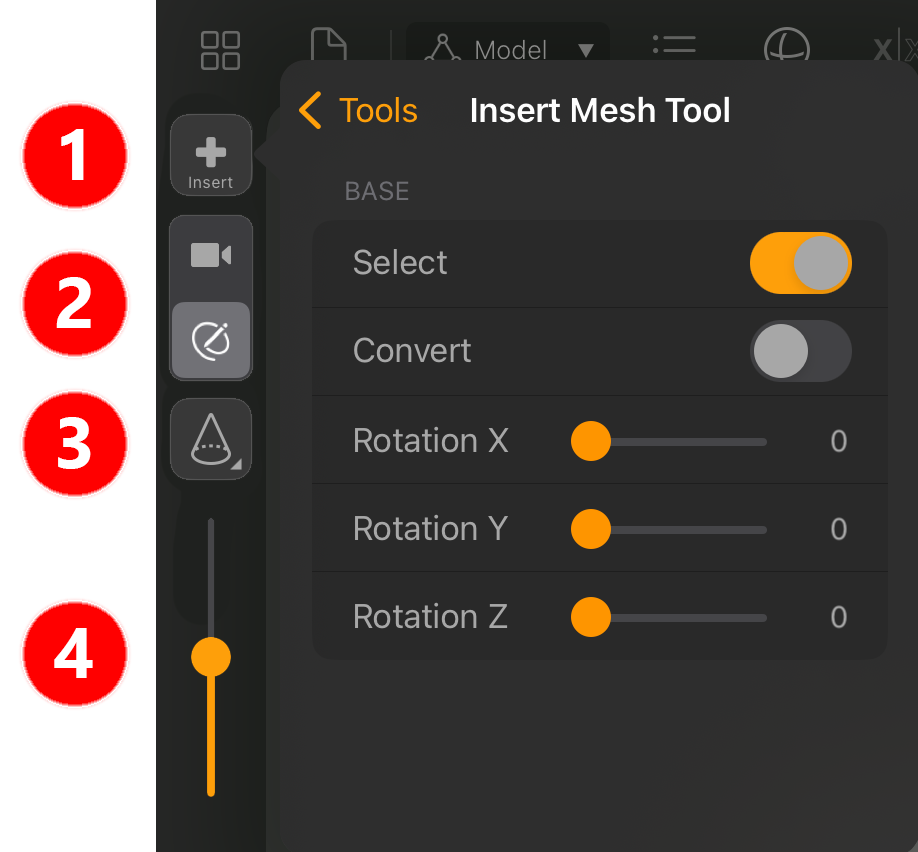
After activating the Object mode and selecting the Insert Mesh Tool, click on its icon in the left Sidebar to open the settings (see number 1). The following options are available:
Select: Newly created objects are selected automatically. This allows their settings to be opened directly via the top menu bar.
Convert: Newly created basic objects are automatically converted to an editable mesh.
Rotation X / Rotation Y / Rotation Z: This can be used to specify the rotation angles of the newly placed object. During placement, it is also possible to rotate around the normal direction of the surface on which the new object is created.
After these settings have been made or checked, a click on the selection button at number 3 opens a list of the available primitive objects. At the end of this list there is an additional Clone option. This will automatically use the object currently selected in the Objects list for object creation.
The object creation itself is triggered by tapping and dragging over any surface in the viewport. Dragging automatically controls the object size and also its rotation around the surface normal. The position over the tapped surface can be controlled by the slider at number 4. Moving that slider all the way to the top will place new objects on the surface. If the slider is set lower, the objects will be sunk into the surface or even placed with their center below the surface.
The icons at number 2 allow a quick switch between camera navigation mode and object drawing mode. New objects con only be inserted if the drawing icon is active. If you like to change the perspective before drawing your next object, just switch to the camera mode. You can then use the default navigation gestures in the viewport without having to deactive the Insert Mesh Tool first.
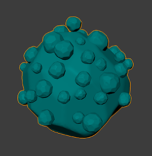
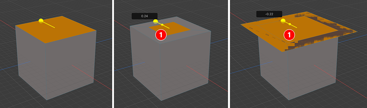
This example shows the use of Clone mode with the Insert Mesh Tool, which allows the selected object to be placed directly as a new copy. By varying the slider position, some copies can be placed standing on the surface or recessed deeper into it. The selection of the type of object to be created can be adjusted at any time without having to exit the tool. All created objects are accessible as individual entries in the Objects list.
Caliper
Allows you to measure the distance between two points. You can also set an amount of segments to divide the line in. This helps measuring distances and proportions.
Extrude
This tool extrudes selected Faces (Polygons), Edges or Points. To extrude:
Select the element and it will be highlighted.
Drag the gizmo by the upper part and you it will extrude the element
Once an extrusion operation has started, drag the middle handle of the gizmo (the arrow head) to adjust the extrusion.
Usng the large gizmo handle again will result in a new Extrude step.
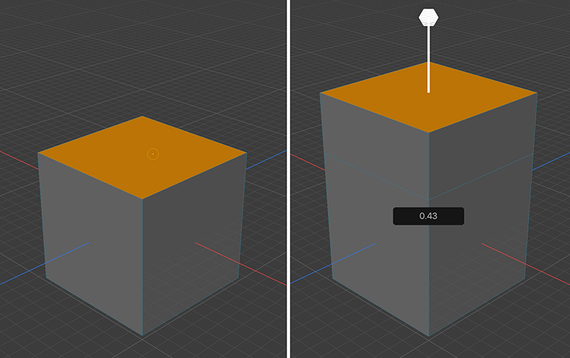
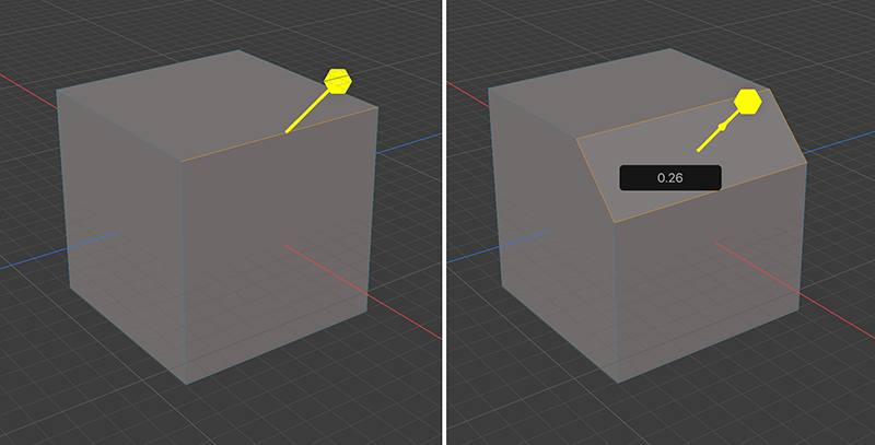
Example of a selected polygon being extruded. This can also be applied to several polygons at once to expand a mesh in different directions.
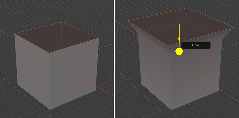
When extruding edges, only edges that are touched by polygons on only one side should be selected. Otherwise, non-manifold structures will be created during extrusion, which would have to be corrected later. In this case, the top edges of a cube were extruded with its top face previously removed. The angle at which the edges are to be extruded can be changed in the tool settings.
The extrusion of points is not useful in every case. However, when using the Inset value or its handle, this function can be used to additionally subdivide the close range of selected points.
Bevel
Works with Faces (Polygons), Edges and Points. This tool turns harsh edges and corners into flattened, rounded, soft elements. It also offers a combination of the tools Extrude and Inset and therefore can be used whenever you need multiple Extrude/Inset modeling steps after each other.
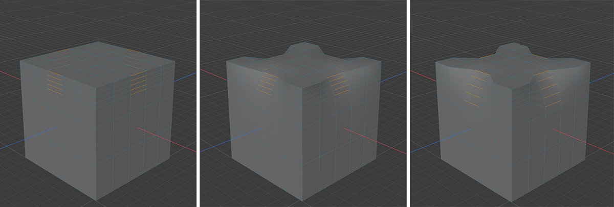
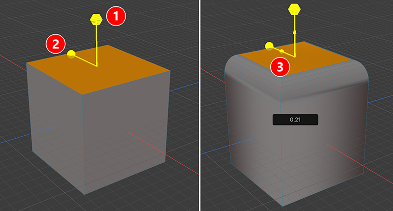
Here the different options of the tool are marked by numbers. By moving the handle at digit 1, a simple extrusion of the selected surface is performed. If the handle at number 2 is moved instead, the selected surface is thereby reduced or enlarged with an Inset operation. The actual rounding of a surface takes place if you first extrude the surface with the drag handle at number 1 and then set the desired scaling with the small drag handle at number 3. The rounding can then be defined in its subdivision and shape via the tool settings. Using one of the large handles again will result in a new Bevel or Inset calculation step.
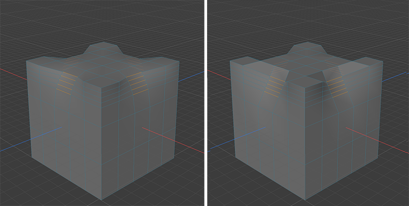
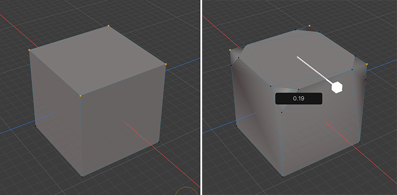
Selected edges can also be rounded. Here, only one handle is available for interactive use of the tool.
Selected points can also be rounded. Here, only one handle is available for interactive use of the tool.
Inset
Works only with Faces (Polygons). This tool operates in a similar way to Extrude. However, in contrast to Extrude, the selected faces are extruded inwards or, optionally, outwards. Take note, that the Bevel tool also offers this functionality.
In a first step drag on the large handle to create a copy of the selected polygons and then to scale that selection. The result can be adjusted afterward by using the smaller handle (see number 1). Using the large handle will always start a new Inset creation.
Bridge
This tool works for Edges and Face (Polygons). Bridge enables you to create connections between unconnected elements. Selections are not required but, if you have a component selected, you will have to select another selected component to create the conection.
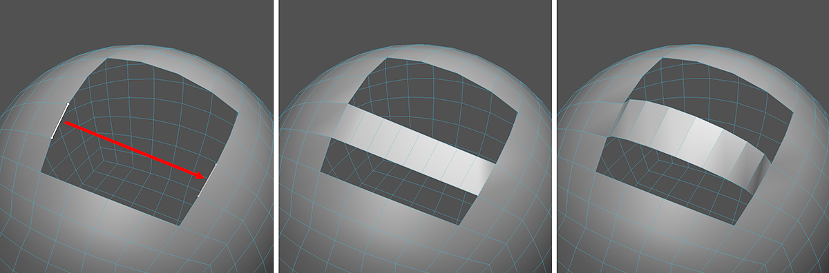
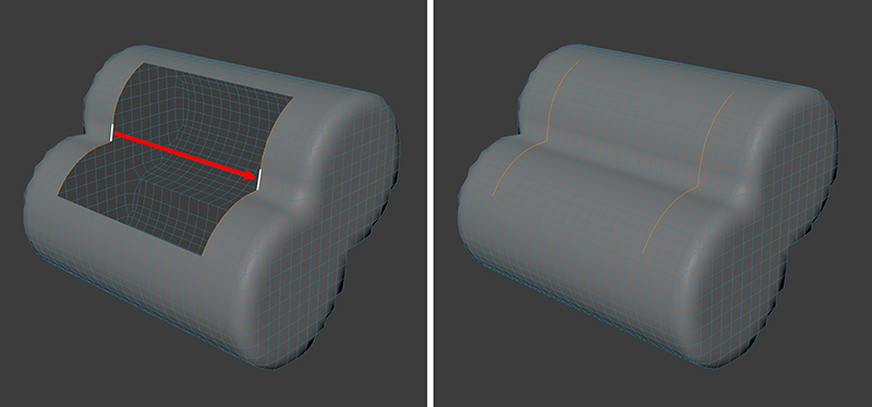
These images demonstrate the process of creating a Bridge between two edges. Just draw a line beween the two edge you like to connect. If more than two edges should be connected, you have to work with selections. The image in the middle shows the result. The image on the right shows the result after increasing the Tension value, to shape the created Bridge. This feature requires more Segments for the Bridge.
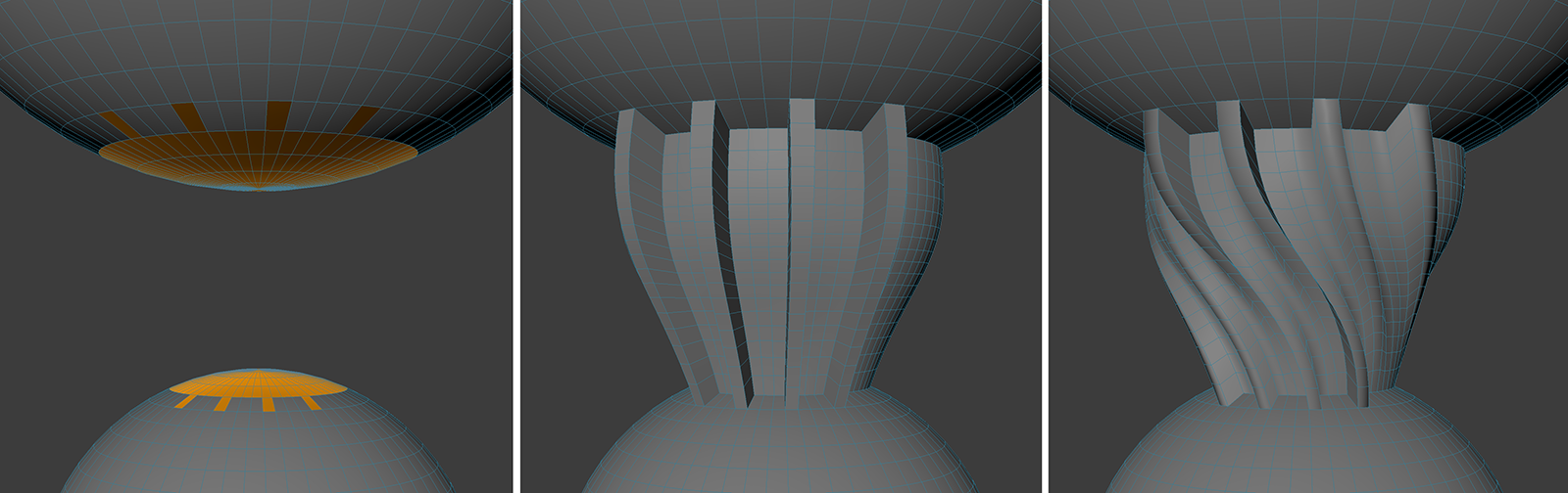
These images demonstrate the process of creating a Bridge between two polygons. Just draw a line beween the two faces you like to connect. If more than two polygons should be connected, you have to work with selections. The second image shows the default result, using no Tension. The third images used an increased Tension value. The last image demonstrates another feature. Spin settings can be used to influence the order of the interconnected points of the polygons. As a result, even twisted bridging is feasible.
The options for the Bridge Tool are:
Segments:The bridges created can be subdivided by increasing the Segments as desired. This is especially important if you want to curve the bridge using the following Tension setting.
Tension: Use this setting to define the degree to which the bridge should be curved. Note that the Segments values must be greater than 0. The curvature direction orients itself according to neighboring edges / edge loops in consideration of various tool settings (e.g., Mode Start / Mode End).
Enable Patching: This mode first works only within "polygon holes" in Edge mode and ignores most other tool settings. Make a selection on the opposite edge in order to give this tool a clue as to how the loops should run. Opposing selected edge pairs will be given a loop matching the surrounding geometry. The best results are achieved when the number of opposing edges matches.
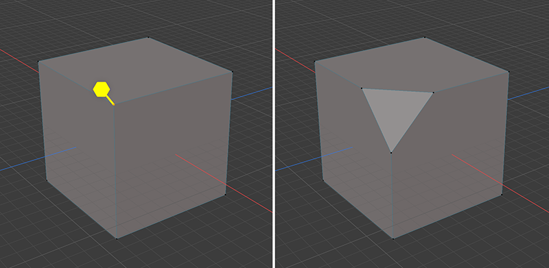
This is an example of using Patching to close a hole in the surface. This technique can be used as an alternative to the Close Hole Modeling Action.
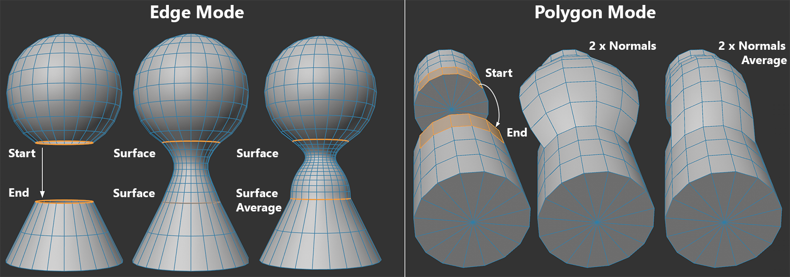
Mode Start / Mode End: These modes represent the curvature transition between the selections to be bridged (if Tension and Segments are both set to >0; otherwise the bridge will be linear). The Start and End is defined by the mouse interaction. if you tap one edge it will be the Start and the End will be where you release the drag action. The following options are available:
Surface: Recommended for connecting selected edges. The surface of the neighboring polygons will be continued (see left half of image below).
Normal: Recommended when connecting selected surfaces at their borders. The larger the Tension value, the more perpendicular the bridge will run to the polygon selection (i.e., increasingly along the polygon Normals) from Start to End.
Surface Average: Like Surface only that a common, average direction will be set for the bridge at the Start and End, respectively (see right part of left side of image below). This mode tends to result in less overshoot for the bridge.
Normal Average: Like Normal only that a common, average Normal will be assumed (see right side of image below).
Flip Start / Flip End: If the bridge you created behaves strangely, e.g., if it runs in the wrong direction - for example from the Start or End to the center of the object - try applying a interpolation sequence to invert the Start and End selection.
Spin Start / Spin End: Normally, selections will be connected with their matching counterpart. First point of the first selection of the target selection, second with the second, etc. Modifying the Spin setting will, for example, let you connect the first with the fifth. This can be seen in the image below. The edges to be connected must create a closed loop (for polygons it's the border edges). The setting can also be used as with the Reverse option (also in combination with it) in order to remove intersecting bridges.
On the left you can see the initial scene. The bridge is created there by a connection from top to bottom between the polygon sections. In the middle you can see the result. On the right, the Spin End value has been increased, resulting in a twist of the bridge connection.
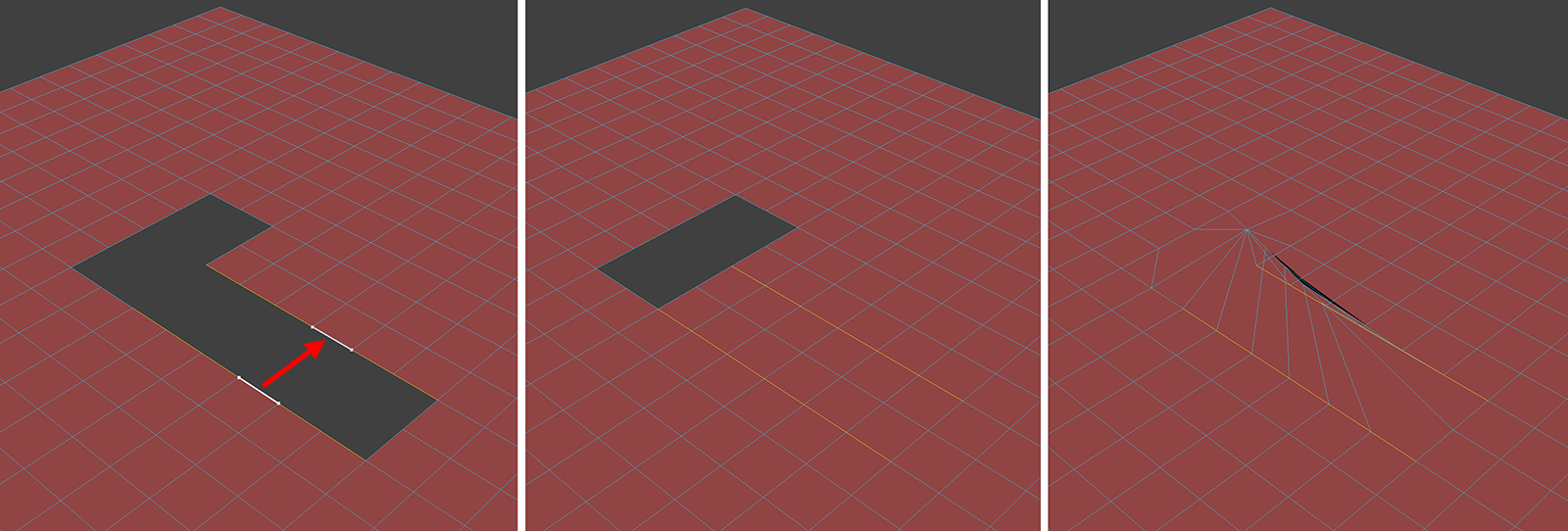
One Sided Patch: It can sometimes happen that both sides of a an edge selection on a polygon hole can have very differing edges. It may then be desired that only the selected edge pairs be connected, as is shown in the image below.
On the left you can see the initial scene. The result in the middle was achieved with One Sided Patch switched on. This option has been off for the result on the right.
Reverse:For two selected polygons to connect or two edge loops, it can happen that the point sequence does not match and the bridge intersects and penetrates itself. In this case you can reverse the option to create a normal connection - the point sequence in one of the loops will then be reversed. Also note in conjunction with this the previously described Spin Start and Spin End setting.
Delete Original Polygons: This has only a relevance when creating a bridge between polygons. These original polygons can be kept or deleted. In most cases, removing these polygons makes more sense so that Non-manifold situations (edges used by more than two polygons) are avoided.
Line Cut
This tool allows creating cuts in meshes. You can start a cut from inside the mesh or from outside.
To start a cut...
Inside the mesh, touch inside it, the point will be snapped to the closest vertex, edge, or face (in that order) of the touched point.
Outside the selected mesh, press the Add Cut Point shortcut, and tap anywhere on the canvas.
Once a cut has started, every time you touch the screen, a new cut point will be added to the line. To finish the cutting action, double tap the green (last) or the red (initial) point.
Loop Cut
Can be used in Faces, Edges and Points mode. This tool tool is primarily used to more finely subdivide edge loops interactively.
An automatic loop recognition (Mode = Loop) or a manually created loop selection (Mode = Path) can be used.
Tap and drag on an edge to create the loop.
Weld
Can be used in Edges or Points mode. This tool can weld points with other points or edges with other edges. By holding the Modifier in the left Shortcut Toolbar, the welding of the elements takes place exactly in the middle between the dragged and the target element. As the polygon structure of the resulting mesh will change by this operation, the tool's settings also provide an option to automatically use N-gons for the newly created or updated faces.
By dragging an edge onto another edge, the dragged edge is fused. This also works with points.
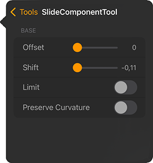
Slide
This tool allows you to slide Edges or Points along the surface of the mesh. Touch on an edge or point and drag it along the surface to slide along the adjacent faces/edges. If you hold down the Modifier you can also move the dragged element into or away from the surface. This can also be controlled directly from the Settings of the tool.
Offset: Can be positive or negative. This is the distance that moves the element along the surface.
Shift: The distance of the element perpendicular to the surface. A Shift of the element outwards is indicated by positive values. A negative value causes the element to sink into the original surface.
Limit: If the option is active, a moved element can only be moved to a maximum of the position of the next point or edge, and not beyond. This avoids a self-penetrating geometry. Using this maximum distance for a point or edge can result in a simular result compared to the Weld action (see next tool description). The only difference is that when using Slide, the touching elements are not optimized and welded into a single element.
Preserve Curvature: The first time you tap an element, its surroundings are analyzed. The surface curvature present at that time is also preserved during gliding. Otherwise, sliding is simply linear, along the initial edge direction in the direction of movement.
Set Edge Flow
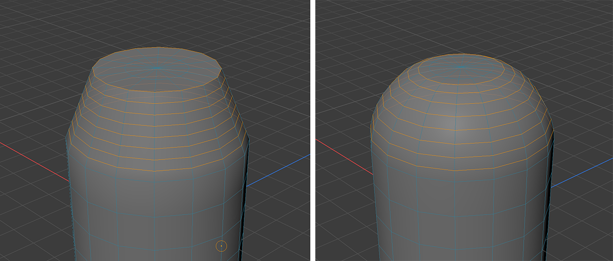
This function is only available in Edge mode. Selected Edges/Edge Loops will adapt to the surface curvature created by parallel Edges/Edge Loops (see example in the following image).
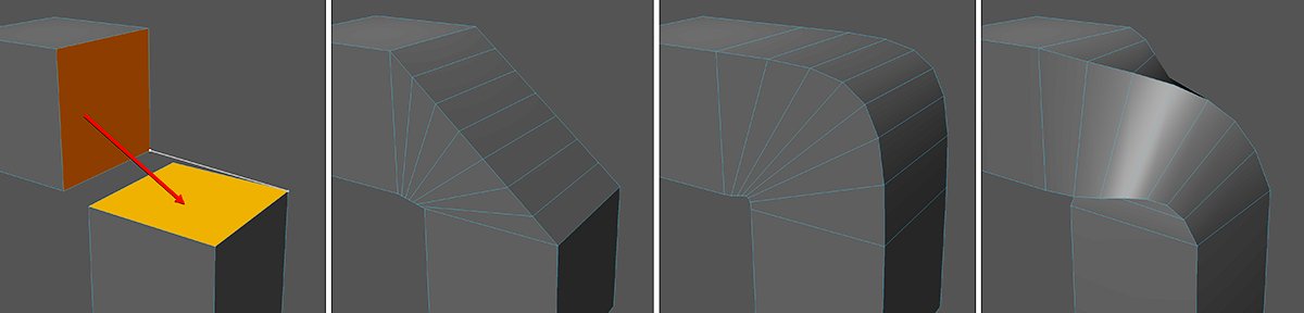
In this example, a Cylinder was converted to an Editable Object and its outer cap edge loop has been dissolved. The resulting slope below the upper cap was subdivided several times with loop cuts (see left image). These edge loops were finally selected and rearranged using the Set Edge Flow Tool. The result is a harmonious transition between the top surface and the sides of the cylinder (see right image).
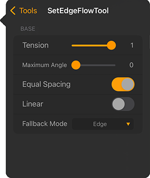
As you can see in the example above, you need a selection of at least one edge, but you can also process multiple selected edge loops at once as well. After the Set Edge Flow Tool has been activated, hold a tap on one of the selected edges and drag upwards at the same time to increase the Tension. After you released the tap you can still adjust the strength of the effect with the tool settings:
Tension: Here you can define the degree to which an edge selection should follow the surface curvature created by neighboring edges/edge loops. This value can be adjusted interactively by tapping and dragging in the viewport.
Maximum Angle: This setting should only be used if the surface curvatures behave strangely. Play around with the values if you get unexpected results. In simple terms, the angle can be used to restrict the effect of the curvature on edge loops that lie outside of the selection
Equal Spacing: Sets the points of the selected edges to equal distances to the neighboring parallel loops (if Tension is set to 1). The following image gives an example of this effect.
The original mesh with an active edge selection is displayed on the left. The image in the middle shows the effect of Tension 1 without Equal Spacing. The image on the right shows the effect of having Equal Spacing active.
Linear: As soon as you set this option, selected edges form a plane with the neighboring parallel edges (see example in the following image).
The left image has Linear switched off, the right image has this option switched on.
Fallback Mode: This mode is used when no surface curvatures of neighboring polygons can be detected. This is then the case if no fitting edge loop can be found or the Maximum Angle setting described above (e.g., for 180°) doesn't allow any. If a fitting curvature is found, this function's settings will be ignored.
None: A linear progression is used.
Edge: The progression is based on the first and last loop of the selection.
Normal: The course is based on the surface Normals of the geometries adjacent to the bridge ends. If no polygons exist there, a linear progression will be used.
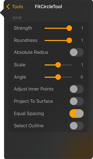
Fit Circle
This function allows selected points, edges and polygons to be arranged in a circle, e.g. to create an exactly circular hole. The tool can be controlled completely via interactive handles in the viewport (see following image) or also via numerical values.
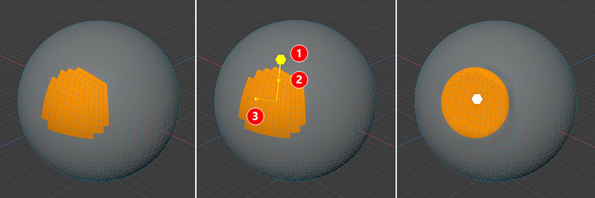
In this example, a contiguous polygon selection on a spherical surface was used. After activating the Fit Circle Tool, the large handle (number 1) was dragged in the viewport towards the center of the selection to finally obtain a polygon area bounded by a disk (see illustration on the right).
As shown in the figure above, the tool provides three different handles. The smaller handles may not be visible until the large handle (see 1) has been moved. This controls the general strength of the tool. If the handle at number 1 is moved towards the center of the selection, the disk or circle shape of the selected elements becomes increasingly visible. This may be a polygon, edge or even point selection. In general, a coherent selection should also be taken into account. If incoherent selected elements are recognized, otherwise also several circular areas can arise.
The handle at number 2 also controls the Strength of the effect, but can be moved back at any time to restore the selected elements to their original state. If you use the handle at number 1 instead, the change is permanent and cannot be fine-tuned in a second step unless you undo the tool effect entirely. The number 2 handle corresponds to the Strength parameter, which can also be found in the Fit Circle Tool Settings.
The handle at number 3 equals the Roundness value found in the Fit Circle Tool settings and controls the final state of the shifted polygons, edges or points. A Roundness of 0.5 means, that a Strength of 1 (equivalent to 100%) will move the outer edge of the selection only halfway towards a perfect circle shape.
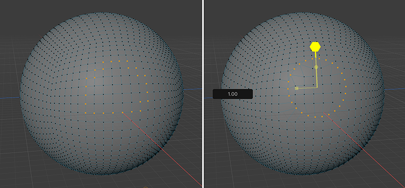
In this example, a point loop is selected on the surface of a sphere and shaped to a perfect circle by using the Fit Circle tool.
Strength: This allows fine blending between the original position of the selected elements and the circular arrangement. How perfect the circular shape achieved at a Strength of 1 is depends on the Roundness value.
Roundness: This allows you to specify the intermediate level of the circular arrangement to be achieved at a Strength of 1. Only with a Roundness of 1 do you also achieve a perfect circular shape at a Strength of 1.
Absolute Radius: This option will exchange the Scale value with an Absolute Radius value to define the target circle.
Scale: This value relates to the size of the original selection and sets the scale of the resulting circle. This parameter is only available with Absolute Radius switched off.
Radius: Here you can enter an absolute radius value for the target circle. This is only available with Absolute Radius switched on.
Angle: By default, the points are placed at the closest position on the circular path. By modifying the Angle value, the points can be moved uniformly on this circle.
Adjust Inner Points: This option ensures that points lying within the specified circle are only moved to a maximum of the circular path and not beyond..
Project To Surface: Note that this option is also avilable as an icon in the left toolbar and ensures that when the Radius or Scale value is increased, the newly placed points are not moved beyond the original bounding surfaces. This option also prevents the curvature of the original surface from being modified and that the moved points are only placed on a level circular path.
Equal Spacing: This option ensures that the moved points are placed evenly on the circular path.
Select Outline: The edges between the moved points are selected automatically. This is only relevant for the Point and Polygon type settings.


 Modifier in the left Shortcut Toolbar, the welding of the elements takes place exactly in the middle between the dragged and the target element. As the polygon structure of the resulting mesh will change by this operation, the tool's settings also provide an option to automatically use N-gons for the newly created or updated faces.
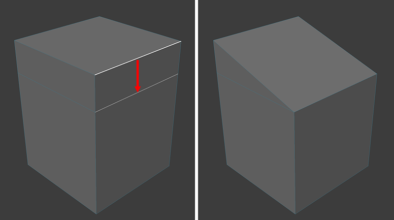

 Modifier you can also move the dragged element into or away from the surface. This can also be controlled directly from the Settings of the tool.