Displacement
Overview
Displacement mapping is a texture-based technique used to push geometry in different directions and add more surface detail. It can be controlled by height field maps (black and white) or vector maps (RGB),these are used to control where the surface geometry is moved and by how much. Unlike its cheaper 'sibling' shader (Bump Map), displacement mapping actually affects shadows and changes the objects silhouette since the geometry is actually moved.
The output of this shader is a displacement vector, when connected to the material displacement input will result in a perturbed surface position and normal. To chain displacement maps together we supply a Displacement Blender shader node which has been optimized to efficiently blend displacement vectors.
Automatic Displacement
In Redshift 3.6.04+, Cinema 4D added support for Automatic Displacement. As long as a material uses a Displacement shader and a displacement texture to drive it the object is displaced automatically. You still need enough geometric detail to properly support displacement but you no longer need to manually enable Displacement or set the Maximum Displacement on a Redshift Object tag.
Manually configured displacement settings via a Redshift Object tag take precedence over Automatic Displacement which ensures compatibility with previously created scenes.
Vector displacement maps still require manually setting the Maximum Displacement. Height field maps support automatic maximum displacement with both single displacement shaders and displacement blenders.
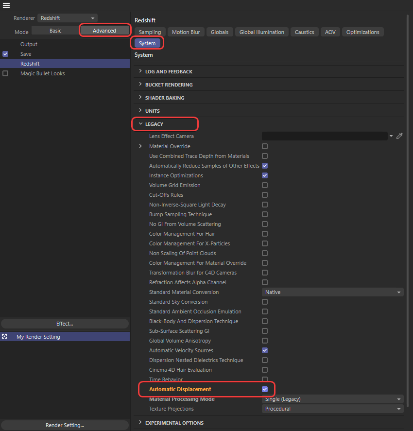
If it's not working, make sure Automatic Displacement is enabled in the Legacy section of the System tab in the Advanced Render Settings as pictured below.
|
| Enabling Automatic Displacement |
Prerequisites
Displacement works in scene units, therefore it is extremely important to have an understanding of your scene's scale.
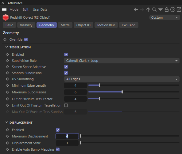
For displacement mapping to work, you must enable tessellation and displacement on your object and the "Maximum Displacement" value must be set high enough to account for the displacement scale. If the Maximum Displacement is set too low, you may not see any displacement at all or it will clip it before it can reach its peak.
Please see the Tessellation and Displacement page for instructions and information on how to do that.
Examples
Simple Displacement
Here is an example of how displacement mapping can enhance the detail of simple geometry.
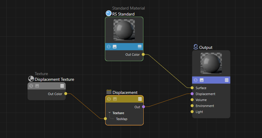
The scene consists of a simple plane that has been tessellated with the default mesh tessellation/displacement parameters and a displacement shader driven by a vector displacement map has been connected to the displacement input.
|
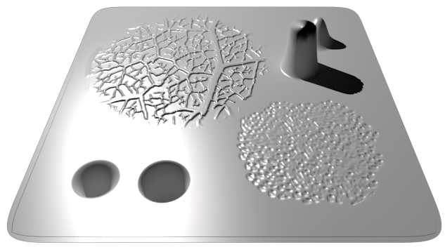
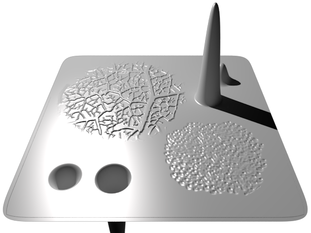
In the image below, see how an otherwise flat surface has geometric detail? The displacement vector map contains a different test in each quadrant. Top-left demonstrates fine perturbation high frequency detail coming out of the plane. Top-right demonstrates large perturbation low frequency detail coming out of the plane. Bottom-left demonstrates large detail, but as an indentation, going into the plane and bottom-right demonstrates fine detail going into the plane. More importantly, note how the top-right tower appears distorted and the lighting looks wrong - this is because the 'Max Displacement' of the mesh is default to 1.0 and so the displacement is being capped to that.
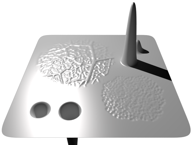
To compensate for the stumpy tower we increase the "Max Displacement" setting in the mesh properties to 4 as seen below.
|
Now the tower stands in all its glory, including the indented tower as can be seen in the bottom-right.
Finally, if we disable "Auto Bump Mapping," below we can see how the low frequency detail towers don't look any different but the fine details now look blurry. Auto-bump mapping allows us to achieve a similar level of visual quality without needing to tessellate the mesh to a ridiculous level which is not recommended as it can have severe performance costs.
ZBrush Vector Displacement
To use a vector displacement map (VDM) from ZBrush it is important to properly setup your ZBrush export preferences.
There are two types of vector displacement, object space or tangent space. Object and World space should only be used for static objects while Tangent space should be used for moving and deforming objects and can also be used for static objects.
ZBrush can be configured to export vector displacement maps in many different ways but Redshift requires the following specific values:
-
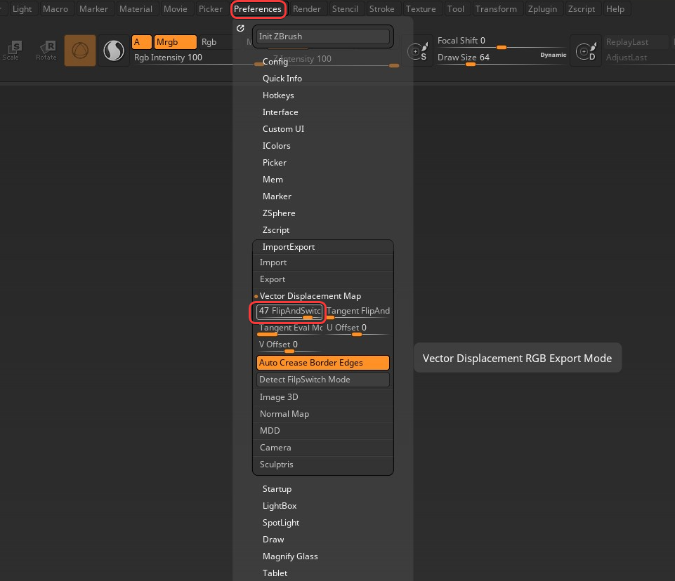
Object/world space VDMs use the value 47 for "FlipAndSwitch"
-
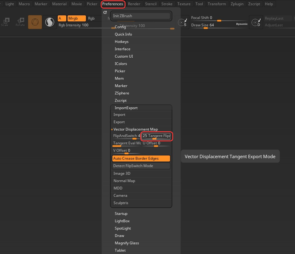
Tangent space VDMs use the value 25 for "Tangent FlipAndSwitch"
These can be configured by going to the "Import/Export" section of the ZBrush "Preferences" menu as pictured below.
|
|
| Configuration for Object / World Space | Configuration for Tangent Space |
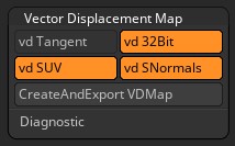
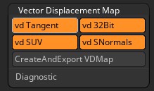
Vector displacement export is controlled by the settings found in the "Vector Displacement Map" section of the "Tools" panel as pictured below.
.png)
|
| Vector Displacement Map settings |
To control which type of vector displacement map is exported use the following settings:
-
To export Object/world space VDMs disable the "vd Tangent" option.
-
To export Tangent space VDMs enable the "vd Tangent" option.
Once appropriately configured the "CreateAndExport VDMap" button or Multi Map Exporter can be used to save the vector displacement file to disk.
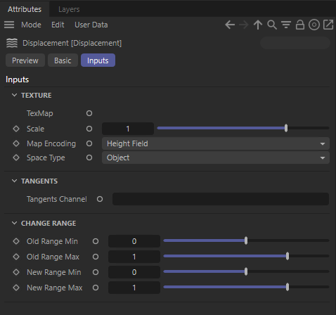
When using the VDM in Redshift remember to interpret the file as raw (not color managed) and set the Map Encoding parameter to "Vector" and the Space Type parameter to match Object or Tangent respectively.
|
|
| Object /World Space settings | Tangent Space settings |
Parameters
|
Texture
TexMap
Connect a texture sampling shader node here to set the displacement map input.
Scale
This scales the displacement value in scene units that is read from the texture. A value of 0.0 effectively disables the technique, yielding the original surface. Greater values increase the displacement effect. Negative values invert the direction of the displacement. The default is 1.0.
Map Encoding
This determines the type of displacement to do, given the texture input type:
- Vector – a floating point displacement vector
- Height Field – a height-field/bump-map scale along the surface normal
Space Type
When computing vector displacement, it can be done in the following geometry space:
- Object – the displacement map is expected to fit onto the object geometry
- Tangent – the displacement map can be applied to any geometry, providing it has a known uv tangent space
Only applicable to Vector type Map Encoding.
Tangent Channel
Specify the UV Set to use for Tangents.
Change Range
Old Range Min / Max
The range of values that are read from the displacement/bump texture.
New Range Min / Max
The new range the values will be mapped to.
UV Context
Connect a UV Context Projection node here to enable inherited connections on all textures upstream from this node for simplified texture mapping. For more information, please see the UV Context Projection page.