Sampling - Production
Overview
|
Rendering Mode
Changing this parameter will change the render settings that are available.
Controls which engine is used for rendering from the following options.
-
Production: Redshift's primary engine for final frame rendering.
-
Live: Redshift's fastest interactive engine, offering near real time updates.
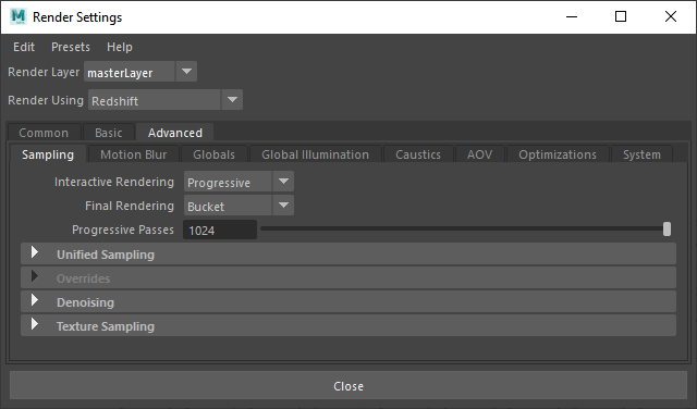
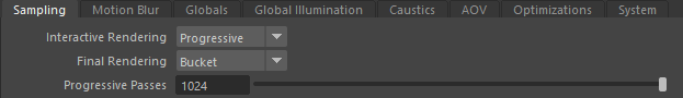
Sampling
|
Interactive Rendering
Sets which rendering mode will be used when starting an Interactive Rendering session, like when hitting the Start / Stop IPR button found in the Redshift Render View.
- Progressive (default) - Intended for fast interactive feedback that favors speed over clean renders.
- Bucket - Intended for high quality final renders that favors high quality clean renders over speed.
Setting Interactive Rendering to Bucket instead of Progressive allows you to make changes to your scene and have your Render View automatically update and respond to those changes. This is great for when you need to preview certain render features that are not supported by Progressive rendering. For more information please see Rendering Modes.
Final Rendering
Sets which rendering mode will be used when starting a new Render / Batch Render, like when hitting the Render button found in the Redshift Render View.
- Progressive - Intended for fast interactive feedback that favors speed over clean renders.
- Bucket (default) - Intended for high quality final renders that high quality clean renders over speed. Bucket mode is always recommended for final renders .
Setting Final Rendering to Progressive instead of Bucket allows you to batch render your scene more quickly using the Progressive render mode. This is great for more quickly previewing the general rendered look of your animations but not intended to be used for final renders.
Rendering Modes
Bucket
Bucket rendering refers to Redshift's high quality final rendering mode. Bucket mode splits the framebuffer into a grid of squares to be worked on one at a time until the entire framebuffer is finished rendering. These squares are referred to as buckets and systems with more than one GPU will render multiple buckets at a time. A bucket is only ever rendered by a single GPU, so the maximum number of simultaneous bucket renders is limited by the number of GPUs setup for rendering in Redshift.
Bucket mode supports all renderer features and uses unified sampling.
Progressive
Progressive rendering refers to Redshift's interactive rendering mode. It renders the framebuffer in multiple passes which start noisy and get progressively cleaner. It is useful for getting fast feedback when shaders, meshes or lights are edited.
Progressive rendering is controlled exclusively by the Progressive Passes setting.
When progressive rendering is enabled, certain renderer features and options have no effect. These are:
- All unified sampling settings (including filtering)
- Point-based subsurface scattering. If you're using point-based SSS, ray-traced SSS (with equivalent settings) will be used instead when doing progressive rendering.
- Photon mapping (including caustics). Redshift's photon mapping implementation is computed as a separate pass so it's only available to production (non-progressive) renders
- Irradiance cache, irradiance point cloud. These are not needed because progressive rendering computes GI in a brute-force way.
- All parameters that have to do with "number of samples". Examples include the number of samples for Depth-Of-Field, number of samples for glossy reflections or refractions, number of area light samples, etc.
Bucket mode is always recommended instead of progressive mode for final renders.
Some AOVs are not computed in progressive mode.
Progressive Passes
Only applies to Production Progressive and Live rendering mode.
Controls the maximum number of passes that can be reached. More passes results in higher quality and the less visual noise.
Since Progressive mode can be used in either Interactive Rendering or Final Rendering the behavior of this setting differs depending on the rendering mode and the situation.
- Progressive Passes with Production Interactive and Live Rendering - When Interactive Rendering the Progressive render will
only reach the maximum number of Progressive Passes if given the necessary amount of time between scene edits and changes.
- For example: If a scene edit takes place before the maximum number of Progressive Passes is reached then a new updated Progressive render will be started and again begin to build back up to the maximum number of Progressive Passes.
- Progressive Passes with Production Final Rendering - In Final Rendering the Progressive render will
always reach the maximum number of Progressive passes before moving on to the next frame, no more and no fewer.
- For example: If your maximum number of Progressive Passes is set to 64 then each frame will be rendered for as long as it takes to reach the 64th pass. Once the 64th pass is reached, Redshift will move onto the next frame and then start the process over for each frame until the entire batch is finished.
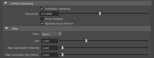
Unified Sampling
|

|
| Maya Unified Sampling
Automatic Sampling Enabled |
Maya Unified Sampling
Automatic Sampling Disabled |
Automatic Sampling
When enabled Redshift will automatically optimize the sample counts per-pixel by using 'Automatic Sampling' which aims to simplify scene setup by removing any reliance on manually tweaking sample counts. The minimum and maximum number of samples to shoot per pixel is controlled by Redshift in relation to the noise present in the scene and the value set by the Threshold parameter.
In Automatic Sampling mode the only parameter that has any effect on sample count (and therefore overall visual quality) is 'Threshold.'
When disabled, Redshift will disable 'Automatic Sampling' at which point the Samples Min and Samples Max parameters are revealed so you can manually control the minimum and maximum number of samples to shoot per pixel.
The Threshold parameter is still used when Automatic Sampling is disabled but it operates within the confines of the manually set Samples Min and Samples Max parameters.
Threshold
This setting controls how sensitive the noise detection algorithm will be. Threshold may also be referred to as the 'Adaptive Error Threshold.;
- Lower numbers detect noise more aggressively which means that more rays will be shot per pixel - resulting in less visual noise.
- Higher numbers detect noise less aggressively which means fewer rays will be shot per pixel - resulting in more visual noise.
It is recommended that you use the 'show samples' feature to visualize the effect of this setting. The default 0.01 value should work well for a variety of scenes. For production-quality results, we recommend lower settings such as 0.003.
|
|
|
|
|
| Threshold: 0.100 Render Time (Min:Sec) : 0:44 Automatic Sampling: Enabled |
0.010 3:20 |
0.005 7:53 |
0.001 22:50 |


The enclosed parameters below are only applicable when Automatic Sampling is Disabled.
Samples Min
Sets the minimum number of primary rays that will be shot per pixel when Automatic Sampling is disabled.
Redshift will initially shoot this minimum number of rays at each pixel and then, if it still detects noise around that pixel it will keep shooting more rays until the pixel is clean enough or if it reaches the 'Samples Max' number of rays.
If you're using depth of field or motion blur, we recommend using at least 8-16 'min samples'.
Samples Max
Sets the maximum number of primary rays that will be shot per pixel when Automatic Sampling is disabled.
Scenes containing strong depth of field or long motion blur might require a fairly high 'max samples', such as 256 or more.
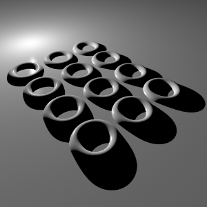
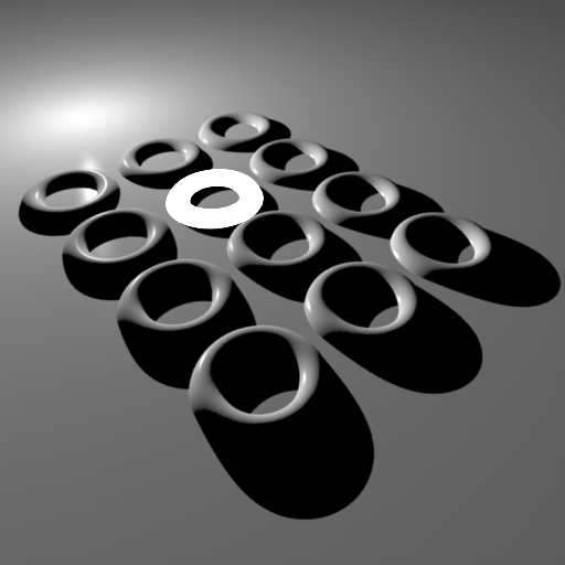
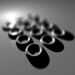
Show Samples
This option enables a debug rendering mode which shows the numbers of rays that were shot for each pixel in a grayscale form.
Darker pixels mean that fewer rays were shot while brighter pixels mean that more rays were shot. A pure white color means that 'max samples' rays were shot for that pixel.
When Show Samples is enabled, the noisy parts of the image will typically be brighter because the unified sampler will shoot more rays to try and clean up the noise.
Random Noise Pattern
When enabled Redshift will randomise the sampling noise pattern on each frame, by default this is enabled.
Techniques such as depth of field, motion blur, brute-force GI, glossy reflections/refractions, AO and area lighting share the same noise pattern so when sample counts for these effects are not high enough and the noise is visible, noise can appear to be 'stuck' on the camera when rendering an animation. Randomize Noise Pattern makes the noise look more like moving TV static or film grain. In some cases this can be more visually appealing.
When denoising is used with an animation we recommend disabling Random Noise Pattern!
Normally, disabling Random Noise Pattern would be undesirable due to making the noise pattern be "stuck on the camera." When denoising, however, it can help significantly because it maximizes the possibility that the noise pattern will remain consistent around a pixel between adjacent animation frames. This reduces the possibility for flickering "splotchiness" on the final denoised results which can be very distracting.
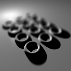
Filter
The Filter defines how the per-pixel samples will be combined together to produce the final pixel color together with the filter Size parameter. There are five options:
- Box - blurriest filter
- Triangle
- Gauss (default) - most "neutral" filter
- Mitchell
- Lanczos - sharpest filter
You can control the final 'blurriness' of the filter using the "Filter Size" parameter. A thing to remember here is that, the sharper the filter type, the larger the filter size typically needs to be. For example, Gaussian filters work fine with values like 2.0, 2.5 and 3.0 while Mitchell typically works best with values like 3.0, 4.0 or 5.0.
A sharpening filter such as Mitchell or Lanczos in conjunction with a small filter size (like 2.0) will accentuate pixel 'jaggies' as well as noise!
Filter Size
The Filter Size controls the final "blurriness" of the filter. In general the sharper the filter type the larger the filter size needs to be.
For example, Gaussian filters work fine with values like 2.0, 2.5 and 3.0 while Mitchell typically works best with values like 3.0, 4.0 or 5.0.
Choosing a filter type and filter size highly depends on what you are rendering. For example, still images can often get away with sharpening filters such as Mitchell or Lanczos. Animations, on the other hand, usually work best with blurrier filters, like Gauss. The reason is that 'jaggies' are particularly visible on animations!
On some renderers 'filter size' refers to the filter radius. On Redshift, 'filter size' refers to the filter's diameter ! For this reason, if you're porting a scene from a different renderer, you might have to double the filter size value in order to get similar results.
|
|
|
|
|
|
| Filter: Gauss Size 2.0 A bit too sharp around the rings. |
Gauss 2.0 A bit too sharp around the rings. |
Mitchell 2.0 Very sharp features. Almost as if antialiasing is disabled. Mitchell filters require larger sizes! |
Mitchell 3.0 Still a bit aliased but looking better. |
Mitchell 4.0 Sharp and relatively smooth. The Mitchell filter typically works best with sizes like 4.0 and 5.0 |


Max Subsample Intensity
Limits the maximum value of intensity for each individual sample. The higher the 'Max Subsample Intensity' the harder the renderer has to work to antialias the image.
Usually monitors can show colors ranging from black (0.0, 0.0, 0.0) to white (1.0, 1.0, 1.0). Any color that is brighter than white (like 10.0, for example) will still be rendered as white. But the internal workings of a renderer do care about these "overbright" colors.
Scenes containing very bright lighting and/or strong emissive materials can be very hard to antialias. The reason has to do with sample filtering: say a pixel was rendered with 64 samples. If most of these samples are mid-gray (0.5, 0.5, 0.5) but there is a single sample that is extremely bright (100.0, 100.0, 100.0), that sample will 'dominate' the final pixel color.
|
|
|
|
| Max Subsample Intensity: 128 All the rings are smooth except the self- illuminated one. That part of the image looks as if no antialiasing is enabled. |
4.0 While there is a little bit of improvement, the self- illuminating ring still shows aliasing artifacts! |
1.0 The self-illuminating ring now renders smoothly. |


There are a couple of important drawbacks to using 'Max Subsample Intensity':
- If you are generating an HDR image, bright pixels will be clamped to that value. If you were hoping to apply bloom effects as a post-process that could limit your ability to do so.
- Clamping the per-sample values means that "light energy" is lost. The effect is especially apparent with high antialiasing settings (i.e. many samples per pixel). The lost energy appears as a darkening effect, especially in a blurry effect like Depth-Of-Field.
The only current solution for both cases is raising the 'Max Subsample Intensity' which, unfortunately, will re-introduce harsh edges on strongly illuminated objects.
The images below demonstrate the "energy loss" with an aggressive 'Max Subsample Intensity' setting.
|
|
|
| Max Subsample Intensity: 1.0 Even though some of the specular highlights are strong, the depth-of-field effect is weak on them. |
4.0 Notice the stronger blurry specular highlights. |
Max Secondary Ray Intensity
Limits the maximum intensity value for secondary rays like glossy reflection and global illumination rays.
This feature is useful for reducing fire-flies that may appear in glossy reflections or refractions, which can occur when a small percentage of rays are unlucky enough to sample extremely hot light sources, while most of the rays do not. The ideal solution would be to use as many rays as it takes to clean up the noise caused by fire-flies, but often this is not practical since many thousand, if not infinite, ray samples would be required.
Clamping glossy samples is a simple (though not physically correct) solution, which helps ensure that hot samples are no brighter than a specified maximum amount.
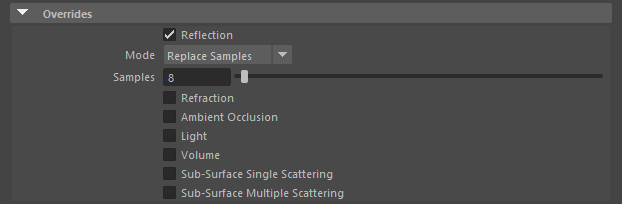
Overrides
|
These options allow you to apply global overrides or scales to the number of samples for the following ray types:
- Reflection
- Refraction
- Ambient Occlusion
- Light
- Volume
- Sub-Surface Single Scattering
- Sub-Surface Multiple Scattering
This is useful for tuning performance or removing noise across your entire scene without having to manually edit materials or lights individually.
Each ray type offers the same options for override control:
- Replace – Fully replaces the samples for the given ray type with a custom value.
- For example: If a light in your scene is currently set to 16 samples then setting a Light override to Replace mode with a value of "64" will force that light and any other light in the scene to render with 64 light samples.
- Scale – Scales the samples for the given ray type with a custom multiplier value.
- For example: If a light in your scene is currently set to 16 samples then setting a Light override to Scale mode with a value of "3" will force that light and any other light in the scene to render with 48 light samples.
Any override will only affect rays of one sample or more. Zero samples will remain as zero samples.
Denoising
|
Enabled
The Denoising Enabled checkbox allows you to quickly toggle denoising on and off.
Denoising lets you easily render images at a reduced baseline quality (lower sample counts) and increased speed at the expense of some potential accuracy. Denoising can only do so much and a balance must be struck between the baseline unified sampling quality and the denoising engine of choice in order to find what works best for your project.
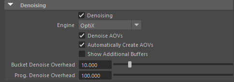
Engine
Sets the denoising engine used when denoising is enabled.
Redshift has three built-in denoising engines and they can easily be switched between here, each one with their own general pros and cons.
- OIDN - Very fast and can be used during interactive rendering but may have more trouble cleaning noise compared to Altus. Compatible with all hardware and GPU accelerated when applicable.
- OptiX - Very fast and can be used during interactive rendering but can have more trouble cleaning noise compared to Altus. Only compatible with Nvidia GPUs.
- Altus Single - Slower (renders the frame once before denoising) and non-interactive but produces good results for final quality renders. Compatible with all hardware.
- Altus Dual - Slowest (renders the frame twice before denoising) and non-interactive but produces great results for final quality renders. Compatible with all hardware.
The images below were rendered with low sample counts in order to better demonstrate the differences of the different Denoising Engines.
|
|
|
|
|
| Denoising: Off Render Time (Min:Sec) : 0:43 |
OptiX 0:44 |
Altus Single 0:49 |
Altus Dual 1:24 |


Denoise AOVs
When enabled - by default, it allows Redshift to denoise AOVs.
Please note that denoising must still be enabled at the individual AOV level in addition to the "Denoise AOVs" paramter being enabled.
When disabled, denoising will not occur on AOVs even if denoising is enabled at the individual AOV level.
Automatically Create AOVs
When enabled - by default, Redshift will automatically add any AOVs that are needed to achieve its denoising results for the specified denoising engine. When disabled the user will need to manually add the necessary AOVs depending on the current denoising engine.
- AOVs used by OIDN andOptix - Diffuse Albedo and Bump Normals
- AOVs used by Altus - Diffuse Albedo, World Position and Bump Normals
Show Additional Buffers
When enabled the additional image buffers used for denoising are revealed in the Render View AOV list. This can be useful when diagnosing denoising.
While Redshift is rendering it generates additional images ("buffers") which are essential for the denoising process. These buffers are normally hidden from Redshift's Render View but if you enable "Show Additional Buffers", those buffers will appear in the Render View's AOV list and will be previewable.
Save Additional Buffers
When enabled the additional image buffers required for denoising are saved out before the denoising takes place, this lets you to denoise the renders after the fact with Altus.
Only applicable to Altus Single or Altus Dual denoising engines.
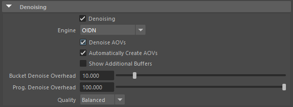
OIDN Settings
|
Quality
Balances speed with quality for OIDN denoising with the following options:
- High - Prioritizes quality over speed, best used for final rendering. Minor differences may appear when comparing results across different hardware architecture.
- Balanced - Balances speed with quality, providing higher quality than Fast and less memory usage than High. Some differences may appear when comparing results across different hardware architecture.
- Fast - Prioritizes speed over quality. Some differences may appear when comparing results across different hardware architecture.
Depending on the scene, there may be no difference in image quality between the three options.
Overhead Settings (OIDN and OptiX)
|
Bucket Denoise Overhead
Controls how much time is allowed for denoising, as a percentage of the total rendering time when using Bucket rendering mode.
This can be a helpful setting to adjust depending on the demands of your scene and in particular with large-resolution renders since Redshift denoises the entire frame after each bucket.
See the table below for some example values and their behavior.
| Bucket Denoise Overhead Value | Behavior |
|---|---|
| 0.0 | Only execute denoising once after all buckets are finished rendering. |
| 0.1 | Allow denoising to take up to 0.1% of the time it has taken to render after each bucket. |
| 10 | Allow denoising to take up to 10% of the time it has taken to render after each bucket. |
| 100 | Allow denoising as much time as it needs after each bucket. |
Please note that the functionality of "denoise overhead" is based on an estimated time to denoise so it does not guarantee that denoising will take exactly the specified percentage of frame time.
Progressive Denoise Overhead
The Progressive Denoise Overhead value controls how often OptiX or OIDN is executed with Progressive rendering mode.
See the table below for some example values and their behavior.
| Progressive Denoise Overhead Value | Behavior |
|---|---|
| 0 | Only execute denoising once after the progressive render finishes rendering (by reaching the maximum number of Progressive Passes.) |
| 0.1 | Allow denoising to take up to 0.1% of the time it has taken to render after each pass. |
| 10 | Allow denoising to take up to 10% of the time it has taken to render after each pass. |
| 100 | Execute denoising after every pass. |
The benefit of lower "overhead" settings is that denoising will take less time. The drawback is that because denoising only gets executed every few passes (in progressive mode) or every few buckets (in bucket rendering), some "visual lag" might be noticeable. That's the reason why Redshift's default denoise overhead is 10% for bucket rendering (where lag matters less and rendering performance more) and 100% for progressive rendering (where the opposite is true).
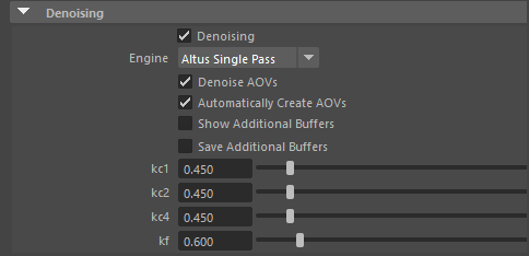
Altus Settings
|
Altus Single / Altus Dual
"Altus Single" means that the frame will be rendered once and then Altus will execute denoising. "Altus Dual" means that the frame will be rendered twice. The two images are then compared to find and remove the noise.
The newer Single Pass technique can determine per-pixel noise in a single render pass. This approach is much more natural as it doesn't double the render time.
We recommend using the "Altus Single Pass" denoise engine, especially if you are a new Altus user!
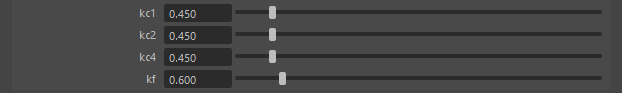
kc1
Controls how much high-frequency detail will be retained (i.e. sharp image features)
Lower kc1 values will retain more high-frequency detail while higher values will make the denoising stronger in those areas. I.e. it will produce smoother results but it might lose details.
kc2
Controls how much medium-frequency detail will be retained
Lower kc2 values will retain more medium-frequency detail while higher values will make the denoising stronger in those areas. I.e. it will produce smoother results but it might lose details.
kc4
Controls how much low-frequency detail will be retained (i.e. chunky image features)
Lower kc4 values will retain more low-frequency detail while higher values will make the denoising stronger in those areas. I.e. it will produce smoother results but it might lose details.
kf
Controls how much influence the additional AOV image buffers are used to affect the denoising results.
Lower values shift the denoising result in the direction of an overall more noisy image but one that retains more of its original details, deriving more of an influence from the additional AOVs.
Higher values shift the denoising result in the direction of a smoother and less noisy image, deriving less of an influence from the additional AOVs.
If you have a bump map and you see Altus smoothing the lighting on it too much then lowering the kf value can help in retaining that bump detail. Kf values that are too low, however, will constrain the denoiser which means that if the image is very noisy it will not be able to denoise the image adequately around these "bumpy areas."
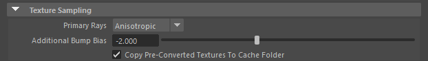
Texture Sampling
|
Primary Rays
Sets the texture mapping method for primary rays. The methods to choose from are:
- Anisotropic - High quality texture mapping but slower
- Bilinear - More blurry texture mapping but faster
- Point - More blocky texture mapping but faster
Additional Bump Bias
Sets a global bias to bump and normal map fidelity, -2 by default.
Lower values can increase the sharpness of the bump / normal maps by decreasing the MIP-map levels used.
This setting can be used to quickly bias all the bump and normal maps in your scene in a particular direction.
Values that are too low can result in more noisy images.
MIP-maps are pre-filtered (blurred) versions of textures and are automatically computed by Redshift behind the scenes. MIP-maps are useful in making textures appear less noisy when viewed from far away.
Each texture has several MIP-maps associated with it. For example, a 1024x1024 texture will have 512x512, 256x256, 128x128, 64x64, 32x32, 16x16, 8x8, 4x4, 2x2 and 1x1 MIP maps. Each time the renderer needs to pick a sample for texture mapping it selects two consecutive MIP-maps (for example 256x256 and 128x128) depending on how far away the textured object is from the camera and then filters in-between them.
Copy Pre-Converted Textures to Cache Folder
The option "Copy Pre-Converted Textures to Cache Folder" is used in junction with textures that have been pre-converted using the ' TextureProcessor' tool.
By default this option is enabled, the assumption being that the local texture cache folder has better IO performance than the source texture folder, which is common for example when source textures are stored on slower network drives or when the local texture cache folder is on an SSD drive while the source texture folder is on a mechanical drive. By copying the pre-converted textures to the local machine cache folder, the out-of-core texture file streaming during rendering can be significantly faster, which can have a significant impact on rendering performance. This option should be disabled when the IO performance of the texture cache folder is equal to or lower than that of the source texture folder.