The Move Tool
This tool can be used to select objects by clicking on them and combines the most common functions for placing objects in a scene. It allows objects to be moved freely or restricted along individual axes, and also automatically aligned with other surfaces. This makes placing picture frames on walls, furniture on the floor, or lights on the ceiling a breeze. Finally, there is also a control element for rotations around the vertical axis, which often eliminates the need to switch to the Rotate Tool.
As mentioned earlier, simply left-clicking on the object you want to move in the viewport or in the Objects List is enough to select it. However, you can also select multiple objects at once and then move or rotate them together, for example. To do this, hold down the ctrl (Windows) or cmd key (macOS) while clicking to add more objects to a selection. Objects selected by mistake can be deselected by ctrl/cmd-clicking on them again.
If multiple objects have been selected, the tool’s axis system marks the average position of these objects. This center point is also used, for example, for collision detection with other surfaces during the transformation.
Quick Navigation
Interactive Elements
The movement of selected objects can be carried out in different ways or restricted:
-
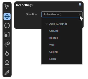
Guided movement: Hold down the left mouse button while the mouse pointer is above the yellow center point of the selected object. The object can then be moved freely within the scene while remaining aligned to surfaces or the XZ ground plane and guided along these elements. The video above demonstrates this effect using the Move Tool's default Auto (Ground) mode. Right-clicking on the Move Tool icon opens a dialog box where you can select the type of alignment. For all modes except Loose, the position of the axis stem on the dragged object is used for snapping:
-
Auto (...): In Auto mode, the tool automatically responds to the selected asset and its axis system alignment. In most cases, this results in an alignment relative to the underlying surface that matches the shape of the asset. You only need to switch to one of the following modes if you want to manually change this default alignment relative to the surface. The term in parentheses in the name of this mode indicates the mode automatically chosen for the selected asset.
-
Ground: The moving object automatically snaps to the XZ plane of the global axes system or to the surfaces that lie below the center point of the object axis system from the viewer's perspective. The object is automatically aligned so that its Z axis is always perpendicular to the surface or plane along which it is being moved.
-
Rooted: As in Ground mode, the moved object remains on the XZ plane of the global axis system or on the surface of the object that lies below it from the viewer's perspective. The moved object is aligned so that its Y-axis always points vertically upwards, i.e., parallel to the Y-axis of the global axis system. This mode is therefore well suited for placing street lamps or trees, for example, which are usually perpendicular to the horizon and not perpendicular to the terrain on which they stand.
-
Wall: As in Ground mode, the moving object remains on the XZ plane of the global axis system or on the surface of the object that lies beneath it from the viewer's perspective. The orientation of the moving object is corrected so that its XZ axes remain parallel to the underlying plane or surface. The Z axis points in the direction of the surface beneath the axis system.
-
Ceiling: As in Ground mode, the moving object remains on the XZ plane of the global axis system or on the surface of the object that lies beneath it from the viewer's perspective. The orientation of the moving object is corrected so that its Y axis is always pointing upwards, parallel to the Y axis of the world system.
-
Loose: This mode differs fundamentally from the modes above. While in the other modes the position of the axis system plays a role, as it is used directly as a reference system for snapping to surfaces, in this mode a bounding box around the geometry of the moved object is evaluated and then snapped to its base surface. This makes it possible to place objects even if the axis system is unfavorable, and it also compensates for minor unevenness on the surface where snapping occurs.
-
The Ignore Scatter option is useful if you want to move an object on a surface where other objects have already been scattered using one of the scatter functions. When Ignore Scatter is enabled, these scattered objects are ignored and the dragged object snaps only to the underlying surface. When this option is disabled, the object can snap to all objects.
-
Offset along an axial direction: Place the mouse pointer on one of the three axes of the selected object and then hold down the left mouse button. The axis will be highlighted in white. The object can now only be moved in the direction of the axis direction clicked on. Please note that when dragging the object axes, there is no longer any automatic snapping or alignment (see following video).
-
Rotation around the Y-axis: By dragging the arc segment between the X and Z axes of the object, it can be rotated around its Y axis (see following video).
Special Functions
Moving a selected object can also be combined with additional keyboard shortcuts. It is important to first press the left mouse button and then hold down the corresponding key:
-
Holding cmd (Mac) / ctrl (Windows) in combination with the left mouse button will create a copy of the moved object. This can be used in combination with the center handle of the axis system, with the individual axes or even while rotating via the arc handle.
Using exact values
Positions, Scale values and Rotation angles can also be read or entered precisely without having to use the interactive tools in the viewport. To do this, simply select the corresponding object and ensure that the Scene area on the right-hand side is open. In the Objects area, below the list of all scene elements, you will find the Transform area, where you can read the Position, Rotation, and Scale of the object.
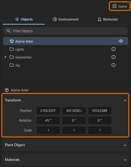
Values can be edited directly by clicking into the value fields and hitting Return/Enter.
When the mouse pointer is placed over a value input field, small arrow symbols appear to the left and right of the value. These can be clicked and combined with additional key combinations to reduce or increase the value in specific increments or even reset a setting to its default value:
- Clicks on the arrows: Clicking on the left arrow decreases, clicking on the right arrow increases a value by 1.
- Shift-Clicks on the arrows: This allows the value to be reduced or increased by 10 units per click.
- Alt-Clicks on the arrows: This allows the value to be reduced or increased by .1 units per click.
- Right-Clicks on the arrows: This automatically resets the value to the default value. For the Position and Rotation values, this is 0 in each case, and for Scale, it is 1 for each of the components. This centers an object again—relative to the parent system—aligns it neutrally, and resets it to its original size.
The Transform values can also be applied to multiple objects selected at the same time, as shown in the following image. The number of elements selected simultaneously is displayed next to their names above the Transform area.
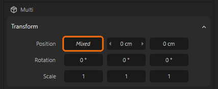
The term “Mixed” is displayed in those value fields where the objects have different values. However, values can still be entered anywhere, which are then applied identically to all selected objects. This allows you to edit the Rotation angles, the Scale or Y Position of multiple objects at the same time, for example.
While the three number fields for Position and Scale represent the position or scale of the object along the X, Y, and Z axes, respectively, HPB rotation angles are used for Rotation. The abbreviation HPB stands for Heading, Pitch, and Bank and has the advantage over specifying rotation angles around the X, Y, and Z axes in that the order in which an object is rotated around individual axes has no effect on the final orientation. Only for the first rotation around individual axes is the result identical to rotations around X, Y, or Z. The terms Heading, Pitch, and Bank stand for:
-
Heading (yaw): Rotation around the vertical object axis (usually the Y-axis). Represents the alignment to the left or right.
-
Pitch: Rotation around the horizontal direction axis (usually the X axis). Moves the "nose" of the object up or down.
-
Bank (Roll): Rotation around the longitudinal axis (usually the Z axis). Tilts the object sideways.
The video above illustrates that individual rotations from the neutral orientation around individual axes function almost identically when HPB values are entered for Rotation. The only difference seems to be that during rotation, the first input field does not represent the X-axis as usual, but rather the Y-axis direction. Accordingly, the second rotation value is responsible for rotations around the X-axis direction. The third value therefore controls the rotation around the Z-axis.
As can be seen in the following video, this similarity changes when an object has already been rotated in multiple directions. Even if it is only rotated around one axis, all three Rotation angles are automatically adjusted. This automatic angle conversion to the HPB system is particularly helpful in animation, e.g., of camera angles, as the order of the HPB angles no longer matters when assigning them to the object. In relation to a camera, the identical viewing direction will always be calculated, regardless of the order in which the H, P, and B angles are interpolated and evaluated during the animation.
HPB angles always ensure that the most direct direction of rotation is implemented in angle animations, thus avoiding unsightly swings in alignment.