The Interface
On this page, you will learn everything about the viewport, the managers and settings windows of Maxon Redshift.
More detailed explanations of individual topics, such as camera, outdoor scene lighting, or working with materials, can be found via the corresponding links in the table of contents on the left.
Quick Navigation
- The Maxon Redshift Viewport
- The Viewport Settings
- Camera and Navigation Settings
- Adjusting the Navigation Mode
- Viewport Navigation
- The Camera Settings
- Adjusting the Perspective
- Depth of Field
- Stored Views
- The Maxon Redshift Menu
The Maxon Redshift Viewport
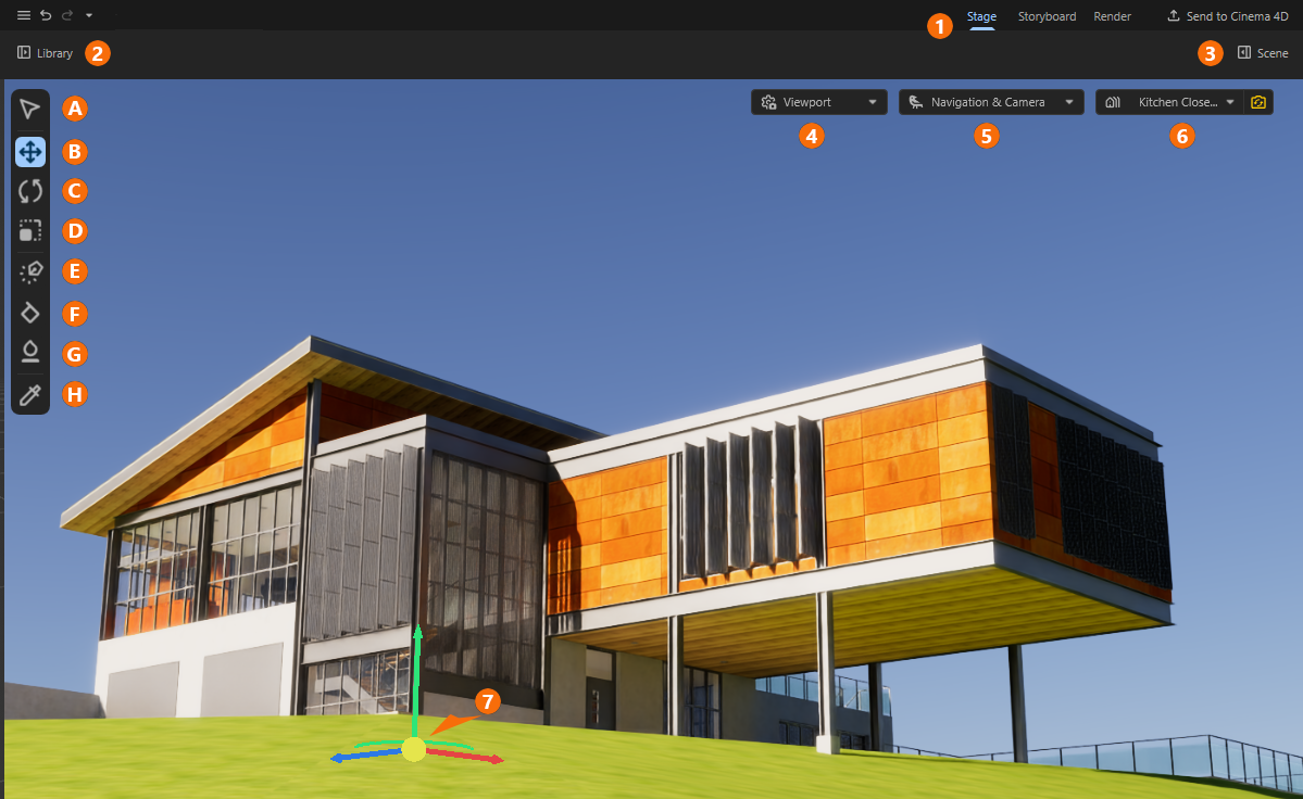
The viewport is the heart of Maxon Redshift, providing a continuously updated view of your scene. As marked in Figure 1, additional menus, buttons, and icons are also available there, which can be used to activate various layouts, managers, and functions. Their meanings are briefly described below. In addition, corresponding links to more detailed information are also provided:
1At the top right, there are three buttons for choosing between different layouts that are optimized for specific tasks:
Stage is the default layout, where you can configure the desired camera positions and angles, add and place additional assets in the scene, and configure the display and lighting for an environment.
Storyboard is mainly optimized for creating animations and camera movements. Working with Stored Views and the Storyboard Manager is described here.
Render provides all the necessary settings required for the final image or animation calculation. This page provides all info on Rendering.
Finally, there is also the Send to Cinema 4D command, which can be used to export an open object to the native Cinema 4D data format. This makes it even easier to add additional animations and simulations to the project, for example. Maxon Redshift is also available as a renderer in Maxon Cinema 4D by default, so the same render qualities can be used there.
2This button can be used to show or hide the Library Browser on the left-hand side. This allows you to load additional objects and materials directly into the scene, for example.
3The Scene Manager can be shown or hidden using this button on the right-hand side. This area contains a list of all Objects and Materials in the scene, configuration options for an Environment, and input options for numerical values and other parameters.
4The Viewport Settings allow you to control the render quality in the viewport.
5In the Camera & Navigation menu, you can control the properties of camera navigation in the viewport and also access the Advanced Camera Settings.
6This Stored Views list allows you to store your own data packages for the camera, object positions, or even the current time of day, which is used for the environment simulation. This allows us to return to specific angles of the scene at any time. The entries stored in this list can also be arranged in the Storyboard layout to create animations with camera movements.
7Some tools cause additional elements to be displayed in the viewport, such as an object axis system for the currently selected object, which is provided by the Move Tool.
On the left side, there is a vertical icon palette with the most important tools and modes for interactively selecting and placing objects within the scene:
AThis Selection and Navigation Tool allows you to move through the scene as a viewer using mouse movements. In addition, objects can also be selected by simply left-clicking on them in the viewport.
BWith this Move Tool, objects can be selected by clicking on them in the viewport and then repositioned, for example, by dragging their axes. Additional options ensure automatic alignment and placement of moved objects, e.g., to always place them vertically on the ground or on a vertical wall. An additional curved handle element also allows interactive rotation of the selected object around the vertical axis. This is useful for placing and rotating objects in a single step without having to change tools multiple times.
CWith this Rotate Tool, objects can be selected by clicking on them. Rotation bands then appear around the position of the object, which can be used to rotate the object around individual axes by dragging it with the mouse.
DWith this Scale Tool, objects can be selected by clicking on them and scaled individually by dragging on their axes.
EWith this Add Tool, currently selected objects in the Library Browser can be added to the scene just by clicking in the viewport. With every click a new copy of that element is created.
FThis Surface Scatter Tool allows you to quickly fill larger areas with many object copies. This can be helpful, for example, when placing pebbles or blades of grass on a landscape.
GThe Scatter Brush Tool makes it easy to paint multiple object instances onto surfaces. This allows you to quickly place groups of bushes or flowers individually, for example.
HWith this Material Sampler Tool, you can quickly copy materials already assigned to objects and transfer them to other objects.
The Viewport Settings
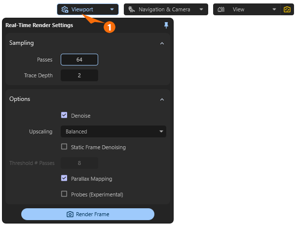
The Maxon Redshift Viewport displays a rendered view of the loaded scene and is updated automatically. The quality and type of this calculation can be adjusted via the Viewport settings (see 1 in Figure 2). As a rule, you do not need to edit anything here at first. It is only worth taking a look at these settings if you want to further adjust the display quality in the viewport or, for example, enhance the responsiveness of the update during navigation. Similar, but with additional settings, Render Settings are also offered for the final frame or animation calculation. On this separate documentation page, you will find both the viewport and final Render Settings discussed.
Camera & Navigation Settings
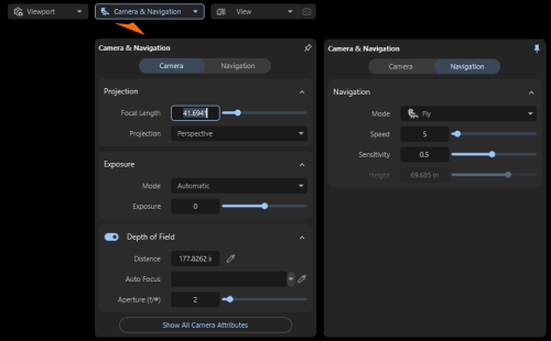
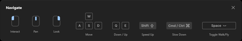
When you first open the Maxon Redshift window, you will mainly see the 3D view of the project, with tips on keyboard shortcuts and mouse assignments for navigating in 3D space displayed at the bottom. There are various Navigation options available (described below in detail). Closely related to this are the Camera settings and the specifications for free and guided navigation, which can all be accessed via the Camera & Navigation Settings at the top of the screen.
Make sure you have enabled the desired synchronization mode for the camera (see Installation & Setup for Revit).
Adjusting the Navigation Mode
There are two different modes available for navigation, which can be switched between by pressing the Space Bar or by clicking the Walk and Fly buttons in the Navigation Settings (see also Figure 3):
- Walk: When navigating, the camera behaves like a human viewer walking across the floor. Although ramps and stairs can be traversed, walls cannot simply be penetrated. Collision detection therefore takes place during navigation. In this mode, the Navigation Settings allow you to specify the desired viewer position above the floor using the Height parameter.
- Fly: In this mode, you have complete freedom to navigate the camera around the scene. You can even fly over buildings or pass through walls.
Both modes offer additional settings to control the speed and sensitivity of navigation:
- Speed: The higher this value is set, the faster the camera will move when using the W, A, S, D keys (to move the camera forward, backward, right, or left) or the Q and E keys (to move the camera up or down). Please note that you can increase the navigation speed at any time by holding down the shift key.
- Sensitivity: This setting is relevant for rotating the camera by placing the mouse pointer within the view and holding down the left or right mouse button. With larger values, the camera rotates faster when the mouse is moved. Take care to have the Navigation Mode enabled for mouse navigation in the viewport (see following descriptions).
As described above, only the Walk navigation mode offers collision detection, so that, for example, unwanted intrusion into walls or other objects cannot occur while exploring the scene. However, this only applies when navigating using the keys (e.g., W, A, S, D, Q and E). If you use the Selection and Navigation Tool in combination with the mouse to move the camera through the scene, collision detection does not take place. You can then, for example, always move further away from the ground or walk through walls.
|
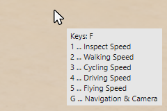
Tapping the F key opens a list of additional shortcuts next to the mouse pointer, allowing you to adjust the navigation speed at any time without opening the Navigation & Camera dialog. |
If you have selected Orthographic for the Camera Projection, the W and S keys can no longer be used to move the camera forward or backward. In this case, use the mouse scroll wheel or the Alt key in combination with the right mouse button to move closer to or further away from the model (see also the following section about the interactive Viewport Navigation with the mouse).
Viewport Navigation

|
In addition to the keyboard shortcuts described above for controlling the camera or viewer in the scene, you can also navigate directly in the viewport using the mouse. To do this, the top icon for Selection (and Navigation) must be active in the left icon palette (see tool palette on the left side). With this tool, you can create a selection by clicking on objects in the viewport and navigate through the scene at the same time. Selecting objects: Simply left-click directly on the object in the viewport that you want to select. You can then switch to other tools to use additional editing options. Please note, however, that other editing tools, such as the Move, Rotate, or Scale tools, also offer direct selection via left-click. Options to rotate the camera:
Options to move the camera:
|
If you move the camera using the mouse buttons, Walk mode will no longer function. There is then always a risk that the camera will be moved through walls, for example, or that the distance from the floor will change from the value specified in Height.
To ensure that the viewer height and collision detection function correctly while moving the camera in Walk navigation mode, the navigation keys W, A, S, D, Q and E must be used.
Navigation via Vectorworks remains possible. With Camera Synchronization active (see configuration notes), navigation in the Vectorworks view can also be used to navigate the Redshift view. Only when navigating in Redshift does the Vectorworks view remain static, as demonstrated in the following video.
The Camera Settings
While the Navigation Settings influence the navigation in the viewport, the Camera Settings provide the camera's Focal Length, special optical effects such as Depth of Field and light amplification. The Focal Length setting is crucial for the image effect when using Perspective Projection and will be discussed in detail in the following section. In short, smaller Focal Length values widen the camera's angle of view, allowing more of the scene to be “seen.” However, this can also increase optical distortion.
The Exposure value can be used to adjust the display brightness independently of the light intensities in the scene.
With the Automatic Exposure Mode the camera can automatically correct the used settings so that there is no overexposure or underexposure, which can cause parts of the image to appear too bright (“burnt out”) or too dark. However, especially in scenes with very bright light sources, such as sunlight in an exterior shot, manual adjustment using the Exposure value may be more appropriate in order to restore a natural-looking contrast ratio and deliberately accept dark shadows.
Switch Exposure Mode to Manual for full artistic control over the brightness levels in the rendered view, although this may result in areas that are overexposed or underexposed. In this mode, you can also adjust the image brightness individually using the Exposure value.
Additional camera settings can be accessed by clicking on the button Show All Camera Attributes and are described on this page.
Adjusting the Perspective
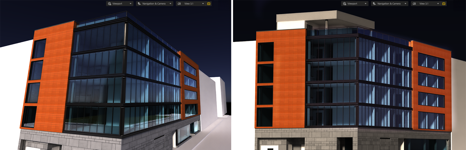
Using the realistic Perspective Projection for the Camera the Focal Length setting in particular should be adjusted individually in order to specify the camera's angle of view and thus the intensity of the optical distortion. A short Focal Length allows a large area in front of the camera to be captured in the viewport and is therefore often used indoors or when a viewer needs to be placed close to buildings but still needs to see much of the surroundings. The disadvantage, however, is that this can lead to greater distortion, especially at the edges of the image. This includes the effect of converging lines, which is often undesirable in technical image representations (see left side of the following Figure 4).
Using larger Focal Length values, on the other hand, causes elements that are further away to be zoomed in closer optically, reducing the viewer's field of view. At the same viewing distance, only a small part of the entire object can be displayed. To compensate for this, the camera often has to be placed further away from the objects, which makes it primarily suitable for displaying outdoor scenes. The combination of a camera position further away from the objects and a longer Focal Length results in greatly reduced optical distortions in the image display, making it much easier to see vertical edges as parallel, non-tilted lines even in the viewport display (see right side of the following Figure 4).
In general, the effect of optical distortion can be reduced by keeping the camera's line of sight parallel to the ground and avoid to angle the view up or down.
In addition to this option for controlling the camera perspective, the type of Projection can also be switched. While Perspective offers the typical range of perspectives that can be rendered by cameras and lenses, switching to Projection Orthographic results in a strictly orthographic perspective in which all perspective distortion is eliminated. Lines that run parallel to each other in the model thus remain parallel to each other in the rendered view, and the proportions between objects are preserved, regardless of the viewing distance. This type of perspective is therefore suitable for more technical views when realism is not strictly required.
Due to the way this perspective is calculated, the camera should be positioned outside the building.
You will learn more about Orthographic projections when discussing Camera Settings.
Depth of Field
Real cameras and lens systems focus at a specific distance to produce a sharp image of a subject. Elements that are closer to or farther from the viewer will appear out of focus. The intensity of this effect depends on the Aperture value used. Maxon Redshift and its camera utilize the same mechanisms, thereby enabling realistic scene rendering, just like a real camera.
By default, the entire scene is rendered in focus, regardless of the distance from the camera. However, if you want to render the subject with a blurred background, enable the Depth of Field option and then enter the Distance at which the render camera should be focused. This is particularly convenient after clicking the eyedropper icon to the right of the Distance field, as you can then click directly on the element in the viewport that you want to render in focus. The distance to the clicked point is automatically determined and entered in the Distance field. The degree of the blur effect also depends on the Aperture.
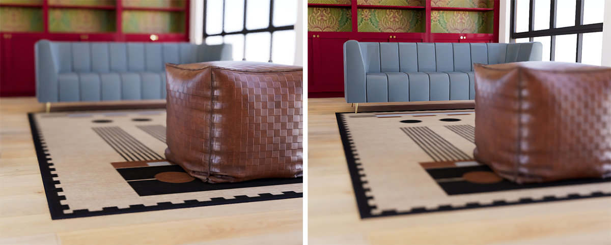
In real cameras and lens systems, the Aperture determines the size of the opening and controls how much light enters the camera and reaches the sensor. This controls both the image brightness and the size of the depth of field. Things are a bit simpler in Maxon Redshift, because we can use this value solely to control blur without simultaneously changing the image brightness. Smaller Aperture values generally result in a faster transition from sharpness to blur. With larger values, image elements located slightly further away from the specified distance remain in focus. This makes the depth-of-field effect more subtle.
If you want to use Depth of Field during a camera move (see the section on the Storyboard feature), it makes sense to assign an object that ensures continuous adjustment of the depth of field Distance. To do this, drag the object you want to keep in focus from the Object List into the Auto Focus field, or use its eyedropper icon to click on the corresponding object in the viewport. The clicked object will then automatically be used for Auto Focus tracking.
Stored Views
It often makes sense to keep different perspectives saved for later use, e.g., to render their views or even to define camera animations (see Storyboard for more info about animations). For this purpose, the current perspective can be saved using the Stored Views Manager and managed there together with other stored views.
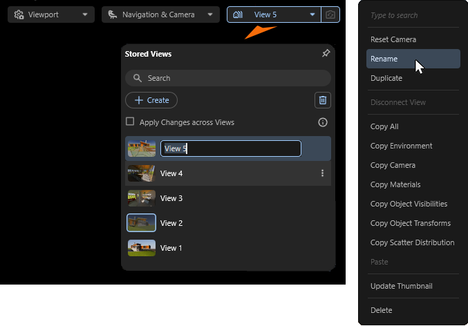
To do this, open the Stored Views Manager using its button directly within the viewport and click the + Create button to save the current viewport perspective. This will create a new entry in the Stored Views Manager with a thumbnail image of the saved perspective. You can also assign a custom name to this perspective by right-clicking on the name to the right of the views thumbnail (see Figure 6 above) and choosing Rename from the context menu. This also allows you to search for specific perspectives using the Search field at the top of the Stored Views Manager and to keep your Stored Views organized.
Stored Views can be selected and activated via the Stored View Manager by double-clicking on their entries. If one of the saved views is no longer needed, it can simply be selected by clicking on it and removed from the Stored Views Manager by clicking on the Trash Can icon on the top right of the manager. Alternatively, you can also right-click on the view you no longer need and select the Delete command from the context menu.
Only views that are not currently active in the viewport can be deleted. The name of the currently active view is displayed in the upper drop down menu at all times. To deselect a view, double-click on another view in the list. At least one view must be present in the list at all times.
|
|
By clicking on the pin icon in the upper right corner of any open settings windows, you can keep them permanently open. This makes work easier, especially when frequently saving views or switching between perspectives in the Stored Views Manager. |
In fact, the Stored Views Manager stores more than just the camera's position, viewing direction, and rendering settings. For example, the time of day and the lighting settings of the Environment are also stored together with the perspective. This also makes it possible, for example, to save different times of day and their lighting conditions and quickly recall them.
Since the + Create button not only saves the current viewing direction and position of the camera in the scene, but also, for example, the time of day and its lighting, different variants of a scene can be managed via Stored Views. For this reason, the Apply Changes across Views option can also be used to specify whether changes within the currently selected view should also be synchronized with other saved views. The change in the time of day would then be automatically transferred to other stored views.
Leave this option disabled if you want to save completely independent states of the scene in Stored Views.
For even more detailed storage and transfer of scene properties between Stored Views, you can also right-click on any Stored Views entry to open a context menu (already displayed in Figure 6). This menu contains various commands for copying and pasting specific data packages, e.g., to manually copy the environment configuration, material settings, object transformation data, object visibility data or scattering specifications between views.
This is particularly helpful if you have disabled the Apply Changes across Views option and therefore changes to settings are only saved in the currently selected view by default.
|
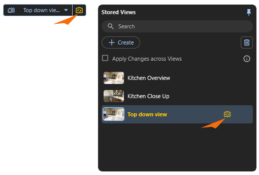
By default, as already mentioned, many changes made within the scene are also stored in the currently active view automatically. However, this does not apply to changes in the camera perspective. You can therefore save a view and then continue navigating as normal without the stored view being continuously updated. However, this can be done manually. If, after saving a view, you decide that you would prefer to save a corrected camera position or viewing direction, simply click on the Sync Camera icon that is found on the right-hand side of the Stored Views menu and to the right of the views name in the Stored Views list (see markings in the left-hand image). |
If you do not want to apply a changed camera perspective to the currently active Stored View, you can also right-click on the view entry in the list and select the Reset Camera command from the context menu. This will reset the moved camera to the exact settings that were originally saved in that view.
The order of the Stored Views can be rearranged by simply dragging them with the mouse.
The Maxon Redshift Menu
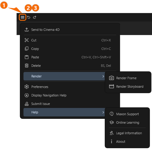
At the top left of the Redshift window, you will find the Redshift menu (see 1 in the figure above) and the typical Undo (2) and Redo (3) functions. Please note that due to the permanent synchronization with your host application and the type of connection to it, not all actions can be supported for Undo/Redo. Here you will find an overview of the general working methods and limitations in the interaction between your CAD host app and Maxon Redshift for Archviz.
File Handling
To enhance your project with additional animations, organically modeled surfaces (sculpting), or water, smoke, or fire simulations, for example, you can use the Send to Cinema 4D function to save the project separately in the native Cinema 4D data format, process it accordingly in Cinema 4D, and then render it there with Maxon Redshift.
Data Handling
The usual Cut, Copy, and Paste commands allow you to copy and paste assets into your project. Please note that there are restrictions regarding objects coming from your host app. These commands can therefore only be used in full with assets that you have accessed via the Maxon Redshift Library Browser and placed in the scene. The same applies to the Delete command, which can also be found here. There are also common shortcuts for all of these commands, which are also displayed in the menu behind the entries by default.
Render Modes
The two commands located here automatically activate the display of the Render Settings in the right-hand part of the window and switch to the settings for rendering of still frames or animations. You can also access the same options by manually switching to the Render layout, as described here.
The Preferences
Here you can open the special preferences for Maxon Redshift, which can be used to configure the units or memory management, for example. You can find a discussion of all the options on this separate page of the documentation.
Display Navigation Help
Use this to manually call up a reminder about the assigned keyboard shortcuts for viewport navigation. In addition to these keyboard shortcuts, you can also use navigation mode and control your camera with the mouse as described here.
Submit Issue
If you notice any malfunctions while using Maxon Redshift for Archviz, you can document them here using our web form.
Help
Here you will find all the resources you need for direct access to instructional videos, Maxon product documentation, and support. General information about copyrights and the current version of Maxon Redshift is also available here.