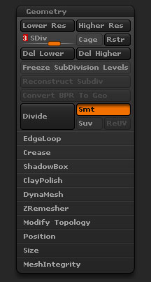
Tool > Geometry sub-palette with sections closed
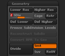
Tool>Geometry sub-palette default items
Lower Res
The Lower Subdivision Resolution button selects the next-lower-resolution mesh from this object’s alternative mesh resolutions. Higher-resolution meshes can be added by pressing the Divide button in the Geometry sub-palette. If this tool is a ZSphere object in Preview mode, use the Density slider in the Adaptive Skin sub-palette to determine the maximum mesh resolution.
Higher Res
The Higher Subdivision Resolution button selects the next-higher-resolution mesh from this object’s alternative mesh resolutions. Higher-resolution meshes can be added by pressing the Divide button in the Geometry sub-palette. If this tool is a ZSphere object in Preview mode, use the Density slider in the Adaptive Skin sub-palette to determine the maximum mesh resolution.
SDiv slider
The Subdivision Level slider selects the alternate mesh resolution. A value of 1 selects the lowest-resolution mesh. Higher-resolution meshes can be added by pressing the Divide button in the Geometry sub-palette. If this tool is a ZSphere object in Preview mode, use the Density slider in the Adaptive Skin sub-palette to determine the maximum mesh resolution.
Cage
When dividing the mesh with smoothing active, the shape and placement of polygons in lower levels change. With the Cage button pressed, ZBrush recalculates the placement of the base vertices so the object conforms to its pre-divided shape. Before generating a displacement map for this object, the original low-res base mesh must be restored. If it cannot be recalled or imported, the Cage button provides a means of approximating it. The button is inactive when the highest-resolution mesh is selected.
Del Lower
The Delete Lower Subdivision Level button removes all lower-resolution meshes from this object’s alternative mesh resolutions. Higher-resolution meshes can be added by pressing the Divide button in the Geometry sub-palette.
Del Higher
The Delete Higher Subdivision Level button removes all higher-resolution meshes from this object’s alternative mesh resolutions. Higher-resolution meshes can be added by pressing the Divide button in the Geometry sub-palette.
Freeze SubDivision Levels
Freeze SubDivision Levels will preserve higher level detail when using DynaMesh.
Reconstruct Subdiv
The Reconstruct Subdivision button attempts to construct a lower-resolution mesh level from the current lowest level. If successful, the new mesh becomes level 1, and the current lowest level becomes level 2.
Convert BPR To Geo
The Convert BPR To Geo button will convert a BPR render result of MicroMesh or FiberMesh into actual geometry that can be sculpted.
Divide
The Divide button doubles the horizontal and vertical resolution of the current 3D tool. Each polygon along the object’s face becomes divided into four polygons — two wide and two high — thus quadrupling the number of polygons which make up the object.
If this object is a polymesh, and no portions of the mesh are masked or hidden, a new, higher alternate mesh resolution is added. You can switch between higher- and lower-resolution meshes and perform appropriate edit actions; ZBrush automatically applies the edits to lower- and higher-resolution meshes.
Smt
The Subdivide Smooth button determines how the mesh will be divided when the Divide button (left) is pressed. With the Subdivide Smooth button pressed, the mesh will be smoothed when divided.
Suv
The Smooth UV button, if pressed, determines that UV coordinates are smoothed when the next Divide or Edge Loop action is performed.
- When the Smooth UV mode is enabled, the UV smoothing is automatically updated when the subdivision levels are changed. This removes the need to manually re-import a smooth UV version of the model or constantly use the ReUV command.
 Dynamic Subdiv
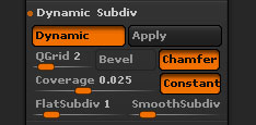
Dynamic Subdivision controls
Changing the different parameters for Dynamic Subdivision can drastically change both the visual appearance of your model and the performance of ZBrush itself. The settings below will help you fine tune your use of Dynamic Subdivision to get the most out of the feature.
Dynamic
Dynamic mode enables Dynamic Subdivision mode for the current Tool or SubTool.
Remember that when first enabling this mode for a model it will not have any apparent effect until you adjust the QGrid, Flat Subdiv and/or Smooth Subdiv sliders to tell ZBrush which mode(s) you wish to use and how strongly.
Hotkey: D or Shift+D as a toggle.
Apply
The Tool >> Geometry >> Dynamic Subdivision >> Apply function converts the model’s Dynamic Subdivision to Classic Subdivision.
This only generates multiple subdivision levels with Flat and/or Smooth modes, due to the fact that those algorithms are based on quadrangle. With QGrid (Quick Grid), using Apply will generate the appropriate geometry as Subdivision Level 1 with no additional levels.
These modes do work together, however, with QGrid being applied first and then followed by the other two. So if your model has settings of 1 QGrid, 1 Flat Subdivision and 3 Smooth Subdivision, using the Apply function will create a model with 5 subdivision levels. QGrid is created as the first subdivision level, followed by a level of Flat Subdivision and three more levels of Smooth Subdivision.
After clicking the Apply function, your model will appear to be unchanged due to the fact that Dynamic Subdivision is a WYSIWYG system. However, you will now have real high-resolution polygons with which to further refine and detail your mesh.
QGrid (Quick Grid)
The QGrid (QuickGrid) slider defines the number of grid-style subdivisions applied to the model. By default, it applies a uniform grid over the entire model. Each increment in the slider’s value quadruples the number of displayed polygons.
The QGrid function works in collaboration with the Coverage, Constant, Bevel and Chamfer options.
When Transform >> PolyFrame is enabled, the QGrid topology is visible but with less intensity than the base mesh topology.
Flat Subdivision and the QGrid Subdivision are based on the same algorithm except that QGrid can use extra options:
QGrid Coverage
The Coverage slider defines how the grid pattern subdivision is distributed across the surface:
- With a value of 1, the distribution is uniform across the surface.
- Lower values slide the highest subdivision toward the edges of your mesh.
While QGrid is active you can see the effect of the Coverage slider in real-time.
To observe an example of this, simply load a Tool >> Initialize >> QuickCube mesh, then set the QGrid slider to 1, the SmoothSubdivision slider to one and change the Coverage slider values. At 1, you will have a very rounded cube because the entire surface is being divided uniformly. As the value approaches 0 you will get sharper edges due to the fact that most of the polygons will be pushed to those areas. (The main surfaces of the cube will have fewer polygons, resulting in less smoothing and flatter sides.)
QGrid Constant
The Constant mode, when enabled, keeps the QGrid subdivision at a constant distance from the base mesh edges, providing uniform topology along these edges.
This setting is enabled by default as it is important to keep a constant radius along the edges when the QGrid Bevel and/or Chamfer modes are active.
QGrid Bevel
The Bevel mode moves the edges of the QGrid subdivision to produce a flat angle along the mesh’s edges.
The Coverage slider as well as the QGrid slider values impact the size and accuracy of this bevel.
QGrid Chamfer
The Chamfer is similar to Bevel in that it operates along the mesh’s edges. However, the edges will be more rounded.
The Coverage slider as well as the QGrid slider values will have an impact on the size and accuracy of the Chamfer.
Flat Subdivision
The Flat Subdivision slider defines the number of grid-style subdivisions applied to the model. It creates a uniform grid across the model’s surface. Each increment in the slider value multiplies the number of rendered polygons by four but no actual smoothing is applied to the surface.
(This is similar to turning off Smt before using Divide with Classic Subdivision.)
Because Flat subdivision does not smooth the surface, it doesn’t make use of the QGrid options described above. The subdivided shape is almost identical to using QGrid with Constant, Bevel and Chamfer all set to 0, except that the polygons will be distributed uniformly.
Smooth Subdivision
The Smooth Subdivision slider defines the number of standard subdivisions being dynamically applied to the model. It applies the same Catmull-Clark subdivision smoothing over the model that you would get using Tool >> Geometry >> Divide. However, these subdivisions are dynamic and display virtual geometry rather than actually creating new sculptable polygons. Each increment in the slider’s value by one will divide the number of polygons by four.
For tech buffs, Catmull-Clark Subdivision splits each quadrangle into four new polygons and uniformly smooths the resulting surface. Triangles are split into three quads and the surface is not smoothed. A model with both tris and quads will be partially smoothed with the first subdivision (wherever the original quads are to be found) and fully smoothed with the second subdivision.
 EdgeLoop
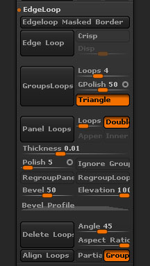
Tool>Geometry>Edge Loop section
Edgeloop Masked Border
When the Edgeloop Masked Border button is pressed ZBrush will slide the masked portion of the surface and create a new polygroup. This would be like using the Slice Curve around your mask.
Edge Loop
When a portion of the mesh is hidden, the Extrude Edge Loop button adds polygons to the edge of the visible mesh’s edges by dividing the polygons which lie along its border. If any points are moved after hiding the mesh portion, the Extrude Edge Loop button only adds polygons between new points’ locations and their old ones. Depending on the settings of the Inner Regroup and Outer Regroup buttons, these new polygons can be assigned a new color-coded group ID, or can be incorporated into the existing group(s).
Crisp
The Crisper Extrude button affects the way the Extrude Edge Loop button divides the edge polygons. When pressed, polygons are divided nearer the outer rim of the visible mesh. When the mesh is divided with smoothing active, this rim provides a crisp corner transition.
Disp
The Displace Amount slider determines by how much the visible groups are extruded (pushed out from the object’s center) when the Extrude Edge Loop button is pressed. If this slider is set to 0, edge polygons are added but no extrusion takes place.
GroupsLoops
The GroupsLoops button will add edge loops around all polygroups. The number of loops is determined by the Loops slider. GroupsLoops can only be used with a model with no subdivision levels.
Loops
Set the Loops slider to the number of edge loops that you want around each polygroup when using the GroupsLoops button.
GPolish
The GPolish slider controls the amount of polish applied to the surface when GroupsLoops is pressed.
Triangles
Turn on Triangles to allow triangles to be used in the resulting mesh when the GroupsLoops button is pressed.
Panel Loops
When the Panel Loops button is pressed ZBrush will convert your existing model into a set of separate surfaces with thickness (panels). These panels will be defined by the polygroups or visible polygons. Various settings alter the final result.
Loops
Each panel has an inner and an outer surface connected by a bridging strip. The Loops slider determines how many loops will used in that bridge. The more complex the bevel shape defined in the Bevel Profile curve (see below) the more loops will be needed to accurately create the bevel. Bear in mind that each loop will increase the polygon count.
Double
When the Double option is turned on panels will be created with front and back surfaces. This is on by default.
When Double is turned off, the panels are created as bevelled sections on the original surface, not separate pieces of geometry.
Append
When the Append option is turned on, ZBrush does not replace the original polygroup and surface when creating the Panel Loop but adds the new panel as a separate piece on top. This is very similar to the Tool > SubTool > Extract function, except for the bevel options possible with Panel Loops.
Note that if Double is turned off then the new panels created will be open surfaces not closed volumes.
Inner
With the Inner option turned on the panels will be created inside the model rather than outside.
The difference between Inner and a negative Elevation setting is in the direction of the bevel shape relative to the original surface.
Thickness
The Thickness slider defines the thickness of each panel, as well as affecting the distance between the panels.
The Bevel Profile curve can also have an effect on the panel cap. If the curve is closer to the bottom of the graph, the cap between each panel will be enlarged.
Polish
The Polish slider affects the amount of polish applied to the panels, especially at the polygroup borders, so as to create smooth edges.
Polish has two different options and you can switch between them by clicking the small circle at the right side of the slider.
An open circle will reduce the over all smoothing. This may create some overlapping where the bevels meet but this can be smoothed later with Polish By Feature (in the Tool > Deformation sub-palette). It may also produce sharp points where three or more panels meet.
A closed circle will result in all polygroup borders being rounded.
Ignore Groups
If only a portion of the mesh is visible and the Ignore Groups is turned on, only the visible polygroups will be used for the Panel Loops process. The advantage of this would be if you wanted to create additional panel pieces caross an already created panel and not have ZBrush create panels for every polygroup.
Regroup Panels
When enabled, the new panels will be assigned a new PolyGroup.
Regroup Loops
When enabled, all loops will be assigned the same PolyGroup without affecting the mesh’s original PolyGroups.
Bevel
The Bevel slider defines the size or amount of bevel on the bridging strip between the panel front and back surfaces.
Elevation
The Elevation slider defines the height of the panel relative to the original surface, letting you specify whether the panels will be raised above or submerged below the surface. A positive setting will result in panels above the surface; a negative setting will result in panels below the surface.
The Thickness and the Bevel settings are related. Having a high value for one and a low value for the other can create unexpected results. For example, if the thickness is set very low setting the bevel to a high value may result in overlapping polygons.
Bevel Profile
The Bevel Profile curve defines the shape of the bevel that is created along the bridging strip between the inner and outer surfaces of each panel.
The left side of the curve is where the bevel connects to the existing surface, while the right side is its outermost edge. The height variations of the curve then define the shape of the bevel cross-section.
The height of the curve controls whether the bevels on adjoining panels will meet or overlap. If no part of the curve goes above the midpoint then the panels will not meet. The more the bevel profile goes above the midpoint, the more the adjoining panel bevels will overlap, and appear to be connected.
Delete Loops
The Delete Loops function analyses the mesh to find edge loops that are not needed for maintaining the general shape of the mesh. It then deletes those loops based on the settings.
Delete Loops uses the curvature of the surface in its calculations and ignores edge loops at mesh borders.
Areas can be masked or partialy masked so as to protect parts of the mesh or modulate the results.
Angle
The Angle slider defines the angle tolerance of the deleted loops. Low values will remove a minimum of loops, keeping the curvature close to the original, while higher values will be more destructive.
Aspect Ratio
The Aspect Ratio slider defines the maximum relative width and height ratio allowed for each new polygon created by the Delete Loops feature. For example, a setting of 4 would mean that a polygon’s height could be no more than four times its width, regardless of the Angle setting.
In other words, ZBrush will first analyse the mesh based on the Angle setting to determine where loops can be removed. It will then check to make sure that the new polygons created by removal of a loop will not exceed the Aspect Ratio setting. If they do not, the edge loop will be removed; if they do, the edge loop will be kept.
Align Loops
The Align Loops function is similar to Delete Loops, except no edge loops are removed. The mesh is analysed in the same way but instead of deleting loops, the topology is adjusted so that the resulting shape is exactly as if the Delete Loops button had been pressed.
Because Align Loops does not alter the number of polygons, you can store a Morph Target first, and then restore parts of the original mesh using the Morph brush, with interesting results.
Partial
Partial mode allows Delete Loops to analyse partial as well as complete loops. For example, a DynaMesh will often produce partial loops where the ends do not meet; this option allows Delete Loops to work with such a mesh.
Groups
With the Groups option turned on, ZBrush will ignore edge loops that define polygroup boundaries.
 Crease
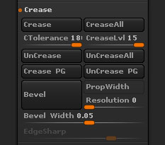
Tool>Geometry>Crease section
Crease
The Crease button adds a tag to the edges of a partially-hidden mesh. When the mesh is subdivided and smoothing is performed, these edges are protected from smoothing. The tag is visible in Polyframes-view mode, as a dotted line which runs along one side of an edge. Creases can be defined on one or both sides of the edge, providing a crease which is partially rounded or not at all. When Crease tags are assigned to the edges of an open mesh (such as a plane object), they protect the edges from shrinking inward when smoothing is performed. Creases are similar to Crisp edge loops, but create hard corners without changing the polygon count in the mesh before subdividing.
Shift-clicking this button assigns Crease tags to the edges of all polygons in the visible mesh portion(s).
Crease All
The Crease All button will crease all edges for the selected mesh.
CTolerance
Crease Edges Tolerance (in degrees).
CreaseLvl
The Crease Level slider works in conjunction with the Crease function and the smoothing which occurs when meshes are subdivided. It determines the maximum number of subdivision-levels in which Crease tags are effective. For example, if this slider is set to 2, Crease tags yield hard corners only in the first two subdivided levels (levels 2 and 3). When the mesh is subdivided to form higher levels, these corners are smoothed. The result is slight rounding in these corners, determined by the resolution of the higher levels.
This slider can be adjusted after subdividing to form multiple levels. If you switch to the lowest resolution (level 1), then adjust this slider, then switch to higher levels, these changes are propogated through the levels appropriately.
Uncrease
The UnCrease button removes Crease tags assigned by the Crease button, from the edges of the visible mesh portion(s).
Uncrease All
The UnCrease All button will remove all creases from the selected mesh.
Crease PG
The Crease PG button will crease the eges of all polygroups.
Uncrease PG
The UnCrease PG button will uncrease the edges of all polygroups. Creasing inside the polygroup borders will not be affected.
Bevel
The Bevel button will apply a bevel to creased edges. The bevel can be adjusted using the settings described below.
PropWidth
When turned on, the Proportional Width option will maintain a constant bevel width when a bevel is applied to creased edges.
Resolution
The Resolution slider determines the number of edge loops that will be created when a bevel is applied to creased edges.
Bevel Width
The Bevel Width slider controls the width of the bevel when a bevel is applied to creased edges..
 ShadowBox

ShadowBox
The ShadowBox button will establish a three sided box that will allow masking on all three planes. By masking out one or all three planes ShadowBox will create a mesh where every there is a mask. If more then one plane is masked then ShadowBox will create a mesh where the masking intersects.
The Resolution of the ShadowBox is controlled by the Resolution next to the Remesh All button. The Resolution must be set before clicking on the ShadowBox button. Remember the higher the resolution the more dense level one of the output mesh will be. By turning on Transparency with Ghost, features such as Radial Symmetry or creating holes in the mesh will be possible.
Res
Shadow Box resolution.
Polish
 Clay Polish
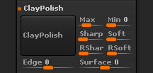 ClayPolish
ClayPolish is a post-process operation which alters the topological structure of your model and moves its edges based on various settings. It has the effect of polishing the surface while sharping and cleaning the angles. It can also create special effects on the model edges.
It can easily simulate the feeling of clay or other raw materials. It can also clean the visual aspect of your model; especially when combined with DynaMesh.
Using ClayPolish is simple: enter your desired settings and then press the ClayPolish button. The feature works with both PolyMesh3D and DynaMesh surfaces. In fact, DynaMesh’s “Polish” mode will automatically apply ClayPolish each time the topology is updated.
Max
The Max Angle slider defines the surface angle at which ZBrush will apply polish. For example, the default angle is set at 25. This means that any portion of a mesh that has an angle higher than 25 degrees will be smoothed.
Sharp
The Sharpness slider controls the intensity of the overall sharpness that is applied to the angles during the polish cycle. This can result in a significant surface change. This slider will also work in conjunction with the RSharp slider explained below.
Soft
The Softness slider controls the intensity of the overall softness that is applied to the mesh surface during the polish cycle. This will give more of a smooth transition across the mesh when its value is increased. This slider will also work in conjunction with the RSoft slider explained below.
RShar and RSoft
These sliders specify the number of times to repeat the sharpening or softening effects defined by the Sharpness and Softness settings. For example, a lower softness effect applied multiple times will have a different result than you’d get with a single softness application at high strength.
Edge
The Edge Contrast slider can be given positive or negative values. Positive settings will inflate the polygons along the edges of the model while a negative setting will deflate these polygons.
Surface
Surface Contrast behaves in a manner similar to Edge Contrast but affects the surfaces between the edges. Positive values inflate these surfaces while negative values deflate them.
 Dynamesh
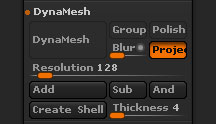 Dynamesh
Turns on Dynamesh for the selected SubTool, remeshing for the first time. Dynamesh is a remeshing operation that creates new topology for your model. The topology is primarily composed of evenly distributed quads, optimized for sculpting. At any point during sculpting (and as often as you wish), simply hold CTRL and drag on an open area of the canvas. ZBrush will instantly retopologize your model to restore a uniform geometry distribution. Even if you have stretched geometry to extreme measures, the result will be a uniform mesh that you can easily continue sculpting.
Group
When enabled, any DynaMesh with multiple PolyGroups will be split into separate pieces. It will still be kept as one SubTool.
Polish
When enabled, this option applies the various ClayPolish settings (see above) each time you update the DynaMesh. This is meant to smooth sharp corners.
Blur
Applies a smoothing effect to the DynaMesh when Project is enabled. A low value generates a small amount of smoothness while a high value will smooth all major details on the model.
Project
When enabled, the current details of the model will be projected onto the DynaMesh automatically. This can be useful when converting a polymesh with existing details to a DynaMesh. Remember that the Resolution setting will play a big part in the amount of detail that can be retained.
Resolution
Defines the Resolution of the DynaMesh, controlling the overall polygon density of the model. A low value will create a low resolution mesh with a low polygon count, while using a higher value will create a high resolution mesh that will retain more details at the cost of a higher polygon count. A low resolution DynaMesh will update faster while a high resolution one will take more time to update.
Add
By default, all new inserted elements will be Additive meshes. This means that when doing the remesh operation, the inserted items will be merged as one element with the original DynaMesh.
Sub
When holding the Alt key while inserting a mesh, ZBrush will consider it to be a Subtractive (negative) mesh. This means that when the remesh is completed, the inserted mesh will be removed from the previous mesh and create holes. The result is similar to a subtraction Boolean operation, but without the messy polygons usually associated with Booleans.
You can insert multiple meshes and add or subtract them all at once via a single remesh operation. You can even mix additive and subtractive meshes, creating different combinations at once.
And
When inserting a subtractive mesh (see Sub action) on top of a additive mesh (see Add action), the remesh action will create geometry only where the two meshes intersect each other. All other geometry will be removed. This operation is very similar to the SubTool Remesh intersection option.
Create Shell
You can create an internal thickness within any DynaMesh by first inserting a negative mesh (Sub). Clicking the Create Shell button will then place a hole where the Insert brush was used and an internal thickness will be added to the whole DynaMesh. The Thickness slider (below) will let you change the size of the thickness, which is inward from the mesh surface. (In other words, it will be inside the model rather than inflating the surface.) This tool is perfect for people who wish print their models in 3D as it will reduce the amount of material for printing and so reduce costs.
If you do not wish to have a hole when Create Shell button is pressed make sure to move the negative inserted mesh away from the mesh before remeshing. It will then be ignored when creating the shell.
Thickness
Defines the thickness of the shell in relation to the resolution of the DynaMesh.
 ZRemesher
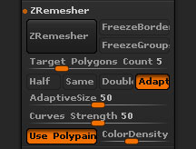
ZRemesher controls
For the ZRemesher section see here.
 Modify Topology
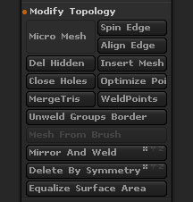
Tool>Geometry>Modify Topology section
DelHidden
Deletes all hidden polygons in a model, leaving only the visible portion.
InsertMesh
InsertMesh allows you to add one mesh into the currently seleted mesh. Use InsertMesh to combine your model into one solid piece without SubTools. To use, the part you adding and the model already selected must either have no levels of resolution or they must have the same number of levels of resolution.
Close Holes
The Close Holes button will close all open holes of a mesh. It is recommend to run the Remesh All followed by a Project All to capture all detail. Close Holes can only be run on a mesh with no subdivision levels.
- Partially hidden meshes: the Close Holes function will close holes in partially hidden models, after which the entire model will be made visible. The surfaces created to fill the holes will have a different PolyGroup.An example of this capability is that you can easily hide a portion of a model, close the resulting opening and then close holes again with the fully visible model to create an internal wall.
Optimize Points Order
The Optimize Points Order button will optimize the points order of the mesh.
Merge Tris
When the Merge Tris button is pressed all triangles will be converted into quads wherever possible.
Weld Points
When the Weld Points button is pressed all unmerged points of the selected SubTool will be merged.
Unweld Group Border
The Unweld Group Border function, located in the Tool >> Geometry >> Modify Topology sub-palette will unweld all the vertices where two or more PolyGroups intersect, creating independent surfaces out of the currently selected Tool/SubTool.
At this point you can assign a new PolyGroup to two or more of these individual pieces. Clicking Unweld Groups Border again will weld those parts back together.
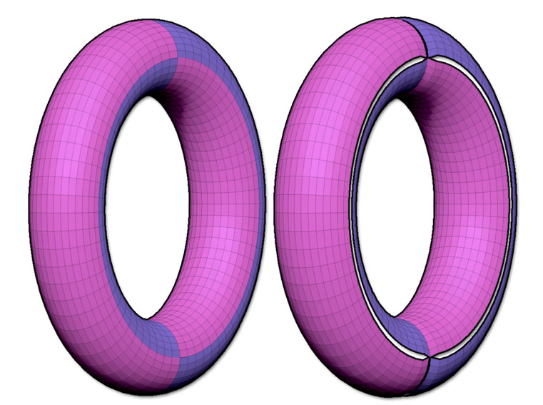
On the left, the original Mesh with two different PolyGroups generated using the Group Front function. On the right, Unweld Group Border was then applied and the torus deformed using the Inflate Balloon deformation. Notice that each PolyGroup is now split from the others.
Mesh From Brush
When the Mesh From Brush button is pressed the selected InsertMesh will be converted into a SubTool. If a SubTool is currently selected the InsertMesh will replace this SubTool. It is recommended to append the PolyMesh3D Star and have that selected when implementing this feature.
Mirror And Weld
The Mirror and Weld button will mirror the tool along the selected axis (X,Y,Z) and then weld all points of the mesh. To establish the center of your tool move the Floor Elevation to 0. When you apply a Mirror and Weld along the Y axis remember that ZBrush is using the center point of the mesh. Moving the elevation of the floor to 0 will give you the visual of what will be Mirror and Weld.
Mirror and Weld will also transfer polypaint information.
Delete By Symmetry
When the Delete By Symmetry button is pressed all geometry on the oposite side of the selected axis will be deleted.
Equalize Surface Area
The Equalize Surface Area button will evaluate the surface and add geometry to surface that has been stretched and is light on geometry. The Tool must be on the lowest SubDiv level in order to activate.
Equalize Surface Area can be applied more then once, however triangles will be created at intersecting points.
 Position

X Position
The X Position slider will move the selected SubTool along the X axis. The value is absolute and so setting the value back to the previous value will restore the previous position.
Y Position
The Y Position slider will move the selected SubTool along the Y axis. The value is absolute and so setting the value back to the previous value will restore the previous position.
Z Position
The Z Position slider will move the selected SubTool along the Z axis. The value is absolute and so setting the value back to the previous value will restore the previous position.
 Size
Size
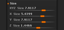
XYZ Size
The XYZ Size slider will adjust the size of the selected SubTool. The value is absolute and so setting the value back to the previous value will restore the previous size.
X Size
The X Size slider will adjust the size of the selected SubTool along the X axis. The value is absolute and so setting the value back to the previous value will restore the previous size.
Y Position
The Y Size slider will adjust the size of the selected SubTool along the Y axis. The value is absolute and so setting the value back to the previous value will restore the previous size.
Z Position
The Z Size slider will adjust the size of the selected SubTool along the Z axis. The value is absolute and so setting the value back to the previous value will restore the previous size.
 MeshIntegrity
 Check Mesh
The Check Mesh Integrity will check the integrity of the mesh for use in ZBrush. This is ideal to track any issues that may have encountered with the mesh, such as non-manifold edges.
Fix Mesh
The Fix Mesh utility is able to repair topology errors such as non-manifold edges in your mesh. It can be useful to run this utility if you find that your model produces topology errors in other 3D packages.