Snap
Enables or disables Snapping.
If disabled, the global Snap settings will be modified for the options below.
If enabled, the tool-specific Snap settings (which will also be saved with the Project file) will be modified for the options below.
If this option is disabled for a given tool while simultaneously pressing the Shift key, the current settings will be used globally.
Mode
Cinema 4D offers 2 Snap methods (Auto Snapping is a combination of 2D Snapping and 3D Snapping):
- 2D: Snapping is done visually (in all views accordingly), i.e., The depth of the object / element position remains unchanged.
- 3D: Snapping is done to the spatially correct point (i.e., the correct depth will also be used) on the target element.
- Auto Snapping: If selected, 3D Snapping will take place in the Perspective view and 2D Snapping will take place in the orthographic view.
Enter the radius around the cursor within which the elements to be selected and the target element should be recognized and displayed with name. If multiple elements lie within this radius, the element nearest the cursor will be displayed. Click to make your selection.
This setting can also be added to Palettes as a GUI element. The
can also be found in the Customize Command Palette and can be dragged from there onto a Palette and used as a normal icon anywhere in the GUI.
If the Dynamic Guides option is enabled, the Guide Angle setting can be used to define the rotation angles at which dynamic guides will automatically be displayed based on special points. A good median value to use is 90°.
This setting can also be added to Palettes as a GUI element. This setting can also be found in the Customize Command Palette and can be dragged from there onto a Palette and used as a normal icon anywhere in the GUI.
Snap Elements
Using the following settings you can define which elements should be snapped to.
If enabled, the selected element can be snapped to any object vertex (incl. those on the reverse side). For Splines, the intermediate points will be used.
If enabled, the selected element can be snapped to any object edge (incl. those on the reverse side).
If enabled, the selected element can be snapped to any object's surface (incl. those generated). This setting should always be used with the Mode setting's 3D Snap option active.
If enabled, the selected element can be snapped to Splines (incl. Spline primitives). They will be snapped to the Spline itself and not to its intermediate points.
If enabled, the selected element will be snapped to an object's origin.
If enabled, the selected element will snap to the intersections of:
- Guides with guidelines
- Guides with Splines
- Guides with polygon edges
- Splines with Splines
- In the orthographic views, visual orientation can be used; in the Perspective view, objects must actually intersect.
When snapping to Guide intersections, note that Guides snapping must also be enabled. A cross-hair will appear within the cursor radius (4x Snap Radius) to signal locations at which an element can be snapped.
If enabled, the selected element will snap to the center of polygon edges or Spline regions between vertices.
Enable this option if you want to snap elements to the work plane. Note that you should also enable The Mode setting's 3D Snap option.
If enabled, the selected element will snap to global grid points or grid points on the work plane.
If enabled, the selected element will snap to global grid lines or grid lines on the work plane.
Enable this option if you want to snap to Guide Objects. Also activate the ![]() Intersection Snap if you also want to snap to intersecting Guides.
Intersection Snap if you also want to snap to intersecting Guides.
Enable this option if you want to snap to Dynamic Guides. Also activate the ![]() Intersection Snap if you also want to snap to intersecting Guides.
Intersection Snap if you also want to snap to intersecting Guides.
Use Perpendicular snapping to snap to lines that run perpendicular along a line (Guides or polygon edges). This is one of the most important Snapping settings. This option is a little more difficult to comprehend but it can be very useful. If used properly you can even do without the orthographic view when modeling. Take a look at the following examples. This should shed some light on the topic.
Example 1
You want to add a cut to the marked line that runs perpendicular to the white line:
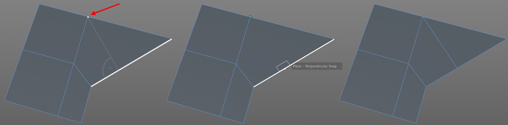
This can be done very easily:
- Enable the Poing and Perpendicular options (you will first have to enable the Guides, and Dynamic Guides options).
- Select the Knife tool and place and hold (without clicking) the cursor over the marked vertex to create a Guide point.
- Now go to the marked line and move the cursor along the line until Perpendicular Snap appears. Now click and drag to the Guide point. Done.
Example 2
This linear, open Spline needs to be closed and the start and end sections meet at the same intersection point. Proceed as follows (the mouse button must be pressed and held during the entire process):
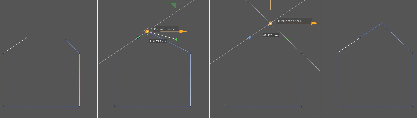
- Enable the Poing, Intersections and Perpendicular options (you will first have to enable the Guides, and Dynamic Guides options).
- Select the Move tool and, for example, grab the right end vertex and drag it to the left start vertex. Hover there for at least a half a second. A Guide point will be created.
- Drag the point to the right to the Guide (that is displayed as an extension of the Spline section) and snap the point to the marked intersection. You can now release the mouse button.
- Close the Spline. Done.
Example 3
A cube and a cone are placed freely in space. We want to drag the 4 top cube vertices parallel to the same height as the tip of the cone.
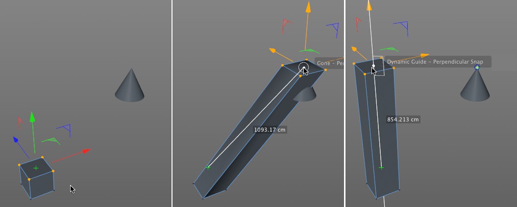
- Enable the Poing and Perpendicular options (you will first have to enable the Guides, and Dynamic Guides options).
- Drag the selected vertices (without grabbing one of the vertices) and hold them over the cone's tip for at least a half a second to create a guide point.
- Keep the mouse button pressed and drag the selected vertices along the Guide (in this case the green Y axis) until Perpendicular Snap appears and snap to that point. Done.
Example 4
A different type of example: Two cubes are placed freely in space. We want to position the selected cube along the right cube without modifying its X coordinates.
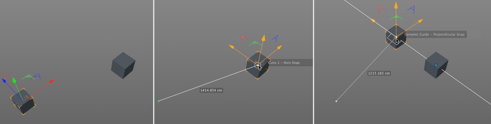
- Enable the Axis and Perpendicular options (you will first have to enable the Guides, and Dynamic Guides options).
- Drag the selected cube with the mouse button pressed over the center of the right cube and hover there for at least half a second (Axis Snap will then be displayed) to create a Guide point.
- Drag the cube to the left along the Guide until the cube snaps into place when Perpendicular Snap is displayed. Done.
This option is designed for use with the Texture UV Editor.
If a texture is loaded in the editor, this option can be enabled to snap UV elements to the pixel corners or centers. This makes it possible to precisely position UV coordinates down to the pixel.
Have a look at the image below:
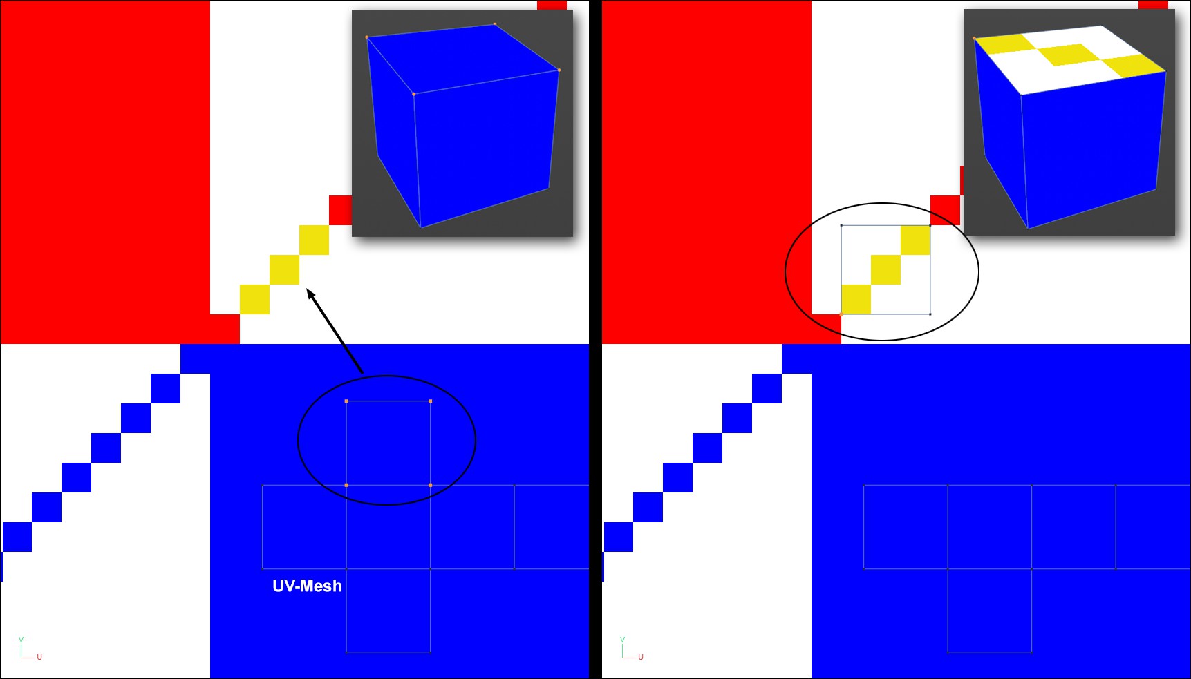
In the image above, a texture in the background is projected onto a cube via the UV mesh shown below. If you want to position one side of the cube's texture precisely over the three yellow pixels, this can be easily done using Pixel Snap. For larger textures you should zoom in accordingly so the pixels are visible. The makes it easier to snap.
Here you can define the snap position in regards to the individual pixel:
- Corner: One of the four pixel corners
- Center: Pixel center