Object Properties
Type
Linear
With this type, a linear, straight spiral spring is displayed between the objects that you define under Object A and Object B. The position of the spring is irrelevant in this case (unless an object has not been defined).
Rotation Spring
A rotation spring is defined here, i.e., a spring that generates a torque (always acting in the center of mass of the object). Rotational springs used to be used in clock movements. The position of the spring should correspond to the common pivot point of the two objects involved (i.e., where a hinge Connector is positioned, for example; you should also place the visual spring plane in the plane of rotation).
Linear + Angle spring
Both spring types mentioned above are effective here.
Drag Rigid Bodies into these two fields (Bullet also allows Soft Bodies).
The two objects can be dragged into the Object A and Object B fields. If you occupy both fields, force or torque is exerted on both objects in accordance with the principle "actio = reactio".
If you leave one of the two fields empty, the principle of "actio = reactio" is overridden; the force or torque acts virtually out of nowhere.
The order in which the two objects to be connected are assigned to Object A and Object B is irrelevant except for the direction of rotation.
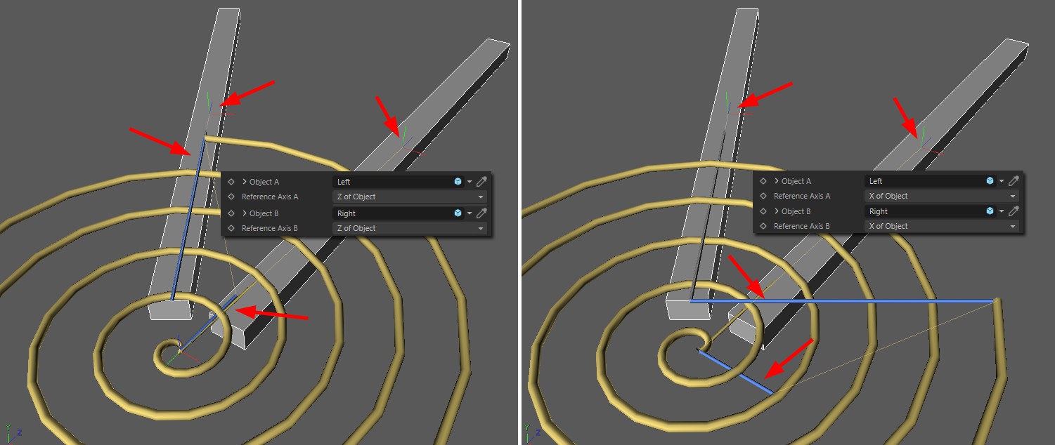
Reference axes are required wherever angles are measured. This is the case with a torsion spring.

Note how the two blue "spring ends" are each aligned with the defined axis (of the linked objects). Object-Y axis would make little sense in this case.

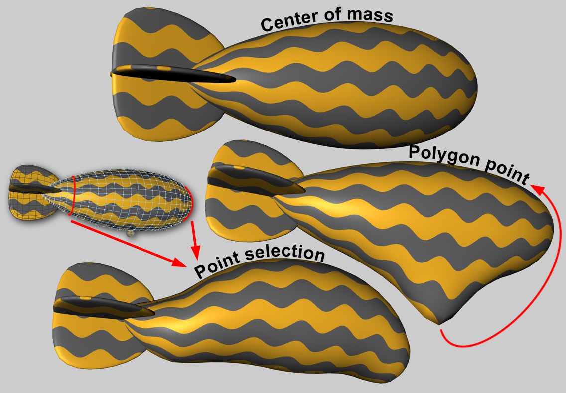
Wherever forces are directed into an object, it is sometimes important in which object area this takes place. If the force acts outside the center of mass, a torque will automatically be generated and the object will attempt to rotate.
The Soft Body is more difficult. Each object point will be connected to other points via springs. If the force will be applied at just one point, the results can be unsightly. Here it is possible to initiate the effect over larger areas.
There are no other parameters for this option, the force acts at the center of mass. With Soft Bodies, this does not result in any deformation.
If this option is selected, an object point can be defined where the force is applied. The Area of Influence can be used to extend the force application to a larger area around this object point. This is only relevant for Soft Bodies. This setting has no meaning for the Rigid Bodies/Connectors combination.
Forces can also be applied by map (Point Selection tag or vertex maps). There are then some additional parameters that regulate how much the shape of the selected (or weighted) points as a whole may change
Index[-2147483648..2147483647]
Index[-2147483648..2147483647]
This is the object index number. Internally, all object points of a polygonal object (also for all generated objects) will be numbered consecutively. This will be displayed interactively in the Viewport if you let the values run through here.
Incidentally, all object points (but here only for truly polygonal objects) are listed in the Structure Manager.
You can drag in a Point Selection tag or vertex maps here.
Since it is not easy for Soft Bodies to process force application at a single object point (this often looks unrealistic), the area of Influence can be used to define an adjustable area around this point where the forces are applied with a linearly decreasing effect. With values of 100%, the entire mesh is recorded, whereby the polygon point (or the point selection) is weighted with 100% and the furthest point with 0%. At lower values, fewer and fewer points react to the application of force; at values of around 1%, only one point or only the selection is affected (although larger values then have an effect internally due to protective mechanisms).
On the other hand, a small value can be useful if you want to couple larger areas defined by point selection (think of tubular Soft Bodies that are attached to an end point circuit via a Connector) to Connectors, springs or motors.
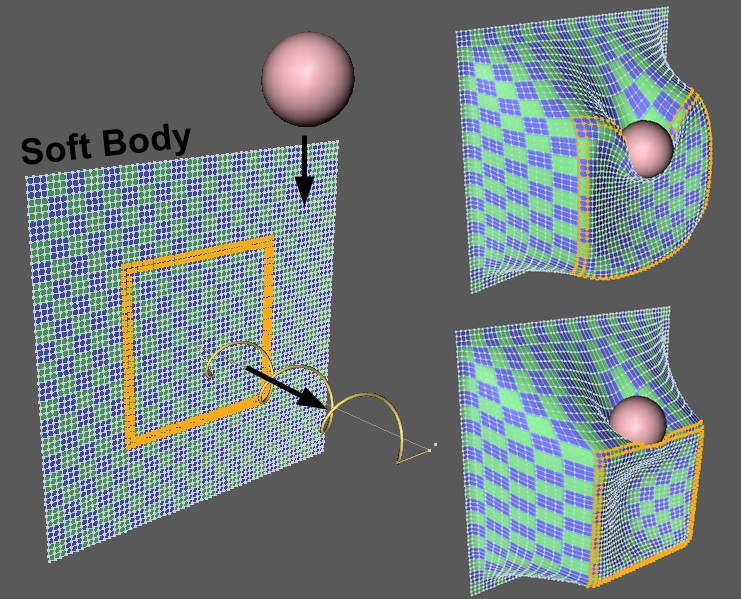
 Marked point selection of a Soft Body is pulled by a spring, at the same time a ball falls onto the selection. Smaller value at top-right, larger value at bottom-right for Shape Retention.
Use this value to define the extent to which the selection or the point geometry influenced by the vertex map can be deformed when force is applied. Small values allow strong deformations, large values increasingly weaker deformations.
The shape retention works internally via springs, the damping of which can be adjusted here. Small values cause oscillations to decay more slowly than large ones.
As already mentioned at Object A, "actio = reactio" applies to both objects. If you want to apply force or torque to only one of the two objects in a physically incorrect way (which should be irrelevant in most applications), you can define this in this selection menu.
The rest length of the spring is the spring length at which the spring does not exert any force. The Set Rest Length button can be used to set the current spring length as the rest length. With the angle spring, you work with the similar parameters Rest Angle and Set Rest Angle.
A spring stiffness (also known as the spring constant in physics) defines how great the forces are that the spring exerts when the length changes from the rest phase. The harder the spring is, the harder it is to compress or extend along its length (and the faster it swings).
Every real spring stops swinging at some point. Material friction in the spring is responsible for this. You can adjust this effect with Damping. If the Damping is 0, the spring oscillates indefinitely (unless damping is defined for the objects involved). The greater the damping, the faster the spring comes to rest during an oscillation.
In addition, damping is important to prevent simulation setups from exploding. Damping absorbs energy from the system so that movements do not build up.
Deforming and breaking springs
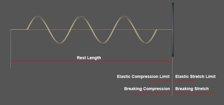
 The values to be entered here refer to the deflection from the spring rest length. The angle spring values work in the same way, only in relation to angular deflections.
As long as a spring is stretched below the lengths/angles defined here (starting from the rest length or rest angle), the spring behaves fully elastically and returns to its rest position or rest angle after the applied force is removed. If the limit values are exceeded, the spring deforms plastically, i.e., it does not return to its rest position after the force has been released and remains deformed.
Brief calculation example: You have a spring with a Rest Length of 100 cm and an Elastic Stretch Limit of 20 cm. You now pull the spring to a length of 150 cm. After the force is removed, the spring swings by its new rest length of 150cm - 20cm = 130cm.
If a spring is stretched or compressed beyond the limits set here (based on the original rest length or rest angle), it breaks, i.e., it behaves as if it were deactivated or simply no longer there.