Bump
General information about bump maps

The settings on this page enable you to simulate bumps.
Figure 2 shows an even surface viewed from the side.
 Figure 2.
The surface has a uniform brightness. However, if you use a bump map for the same surface, CINEMA 4D interprets the brightness values of the picture as height values for the surface (Figure 3).
 Figure 3.
These height values are converted into a profile, whose height affects the inclination of the normal vectors. Although the surface is actually smooth, through the change in the normal vectors an apparently three-dimensional surface with a bump-like structure is created at render time.

Various ways of creating structure
There are basically three ways in which structure can be added to a surface for rendering.
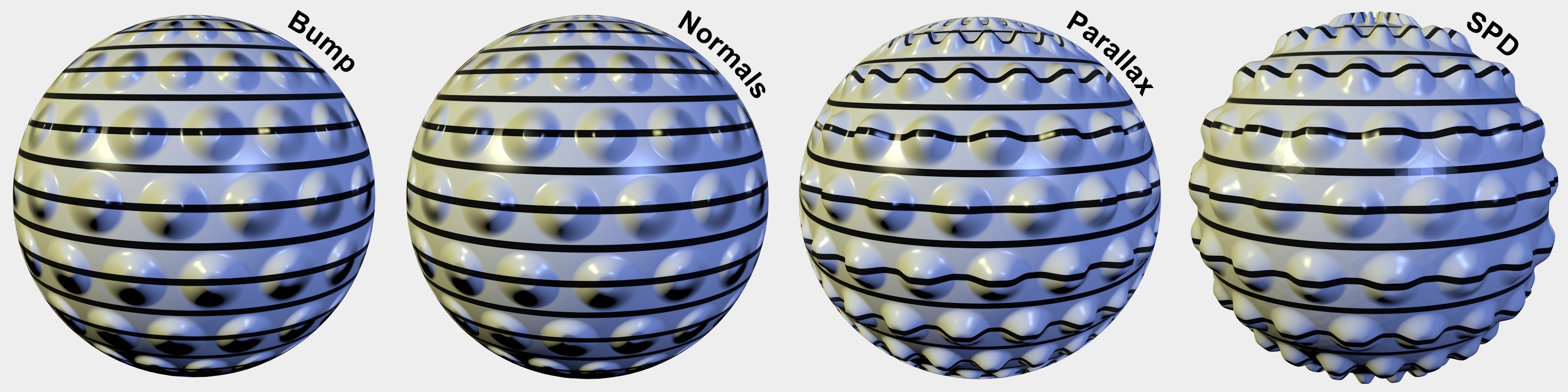 Slight differences between bump maps and Normals but a dramatic difference in quality for subpolygon displacement. Increasing render times/quality from left to right.
The following methods are available, listed in ascending order with regard to render time/quality (whereby the first two use render tricks and the subpolygon displacement actually raises/sinks the surface, thus offering the most realistic-looking results):
- Bump
- Normals
- Subpolygon displacement (with restrictions, normal displacement)
What they all have in common is that they all evaluate a texture's grayscale valuex to define height and depth. So when should which method be used?
Generally speaking, the following rule of thumb can be used:
- High-frequency details such as carpet or fine scratches: Bump or Normal mapping
- Low-frequency details or close-ups such as hilly landscapes, silhouettes, etc.: Subpolygon displacement
However, you should always experiment to achieve the best result for your scene. As always, you have to find the right compromise between render quality and render time.
Parameters
The strength of the bumps. The higher the value, the rougher the surface. If you move the slider to the left, you can choose negative values to reverse the effect of the bump map — bright pixels then cause the material surface to indent while darker pixels elevate the height of the surface.
You can strengthen the MIP/SAT mapping effect when using bump mapping by enabling MIP Falloff. The bump mapping is then reduced the further the surface is from the camera.
 MIP Falloff disabled (left) and enabled (right).
Here an image texture or a 2D shader can be defined. Refer to the Textures chapter for details.
You must use a texture with this channel. It is only from the grayscales in this image that the bump map (a height or relief map) is calculated.
Example

It is very important to have a fitting Shader in the Bump channel (in this example, logically, a Water Shader) in order to make an effect look better. In the example above, the large waves are created with the help of Cloth (Edges are fixed and Wind was both applied to the Cloth tag itself and as a separate Wind Object). Since such smooth waves can only be reproduced in a laboratory setting, the Water Shader (insert center) in the Bump channel is used to create the typical "mini waves", which alleviates you from modeling them.