The Normal Editing Manager
![]()
General
The functions of this manager all revolve around editing vertex normals. Normally, vertex normals are automatically calculated by the Phong Tag, which is completely sufficient in most cases.
If you still want to manually intervene in the alignment of the vertex normals - to apply special shading effects, for example - you must switch off this automatic function. To do this, you need a Normal Tag that saves the vertex normals for each object point. But don't worry, this is created automatically when you change something in the vertex normals.
Otherwise, it can also be created manually from any Phong tag: Simply click the Create Normal Tag button (for this, the object must be polygonal, primitives/generators, for example, must be made editable for this purpose).
- All commands contained here in the Normal Editing Manager are also implemented as separate commands (e.g., Normal Edit - Hard).
- The Property Transfer Manager (formerly VAMP) is well-suited for transferring Vertex Normals between different objects.
- Normals can also be procedurally aligned by using Fields in the Normal tag.
Example
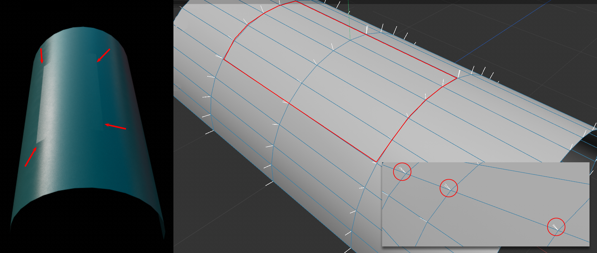
In this example, the rectangular area marked in red on the right has been detached; thus, 2 objects are present. As you can see on the left, this produces shading errors. This is because the superimposed edge points have differently oriented vertex normals.
Solution: Select both objects in the Object Manager, switch to Points mode and select all boundary points. In the Normal Editing Manager, click the Average command described below to get perfect, homogeneous shading across both objects.
The vertex normals and shading
A short excursion into their importance for shading will explain why vertex normals should be touched at all.
In short, the vertex normals in conjunction with the light source position define how bright the shading will appear at the corresponding position.

The more the vertex normals face a light source, the brighter associated polygons will appear. Vertex normals facing away from the light source (more precisely: from 90°) will plunge associated polygons into darkness.
Mesh points have as many vertex normals as there are associated polygons. If the vertex normals of a point are oriented in the identical direction, there is no brightness jump ("hard edge") at the polygon transition, as the image on the left shows.
On the right, the vertex normals per polygon each point in the direction of their polygon normals. This makes the unsmoothed object appear faceted, i.e., each polygon has the same brightness, since the interpolated normals also all point in the same direction.
This can be used, for example, to create hard edges (Fig. below, left). Below, on the right, all vertex normals have been aligned towards the light source, making all surfaces appear maximally bright.

It should be said that the normals can be bent arbitrarily at render time using a Normal Map - also between the mesh points. This lets details be shown without having to use unnecessary geometry.
Selection

The commands affect the vertex normals of selected elements. Since a point can have up to four separate vertex normals, it is necessary to define which vertex normals are considered selected when a point, edge, or polygon is selected.
These vertex normals are considered selected if an element is selected (see also image):
- Polygon: All vertex normals belonging to the polygon, i.e., each polygon vertex has exactly one selected vertex normal.
- Edge: All vertex normals at the edge endpoints, the number is equal to the number of polygons sharing this edge.
- Point: All vertex normals belonging to this point, the number corresponding to all polygons that have a vertex there.
If no element is selected, the effect is the same as if all were selected.
Settings
Space
Some commands are oriented to axis directions (e.g., Align). Here you can select whether the object coordinate system or the world coordinate system is to be used.
Strength
Here you can define how strong the respective command should be. 100% always has a complete effect, while 10%, for example, lets you invoke the command repeatedly to achieve a gradual effect.
Direction
Here you can define a direction in vector terms for numerous commands (e.g., Align). For example, if you want a vector normal to point vertically upwards, enter 0,1,0 here - or simply click +Y - and click on Align. You can define the coordinate system using Space.
This rotates selected vertex normals in the direction defined under Direction.
Distance
The Average command forms an average vertex normal within a certain distance around each selected vertex normal. You can adjust this distance here.
All selected vertex normals will assume their average direction. This also works across multiple objects, as long as the selected elements are within the radius defined under Distance. Specify a Distance of 0 if all vertex normals of one point each are to be averaged with each other.
This splits the vertex normals of selected edges, or the outline of contiguous polygon selections, so that a hard edge is created there.
Regarding edge selections, this command works similar to what ![]() Break Phong Shading does.
Break Phong Shading does.
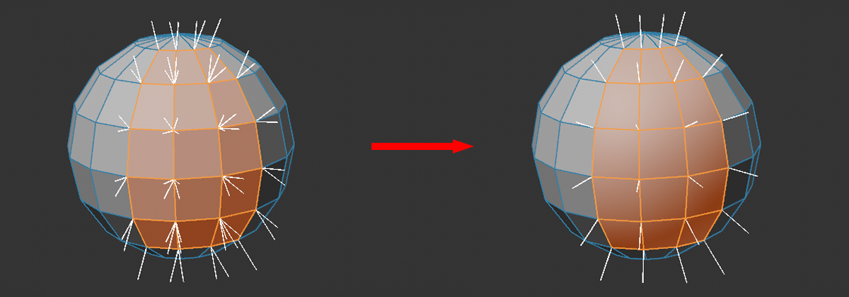
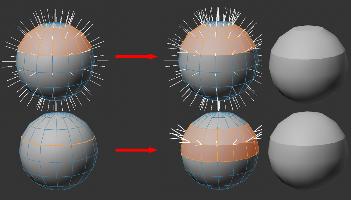
This command turns hard edges back into a smoothed surface, basically what the Phong Tag does with a very large angle - namely 180° - i.e., all vertex normals of a point point in the same direction. This can even turn a cube into something spherical in terms of shading.
These two commands work only for points whose vertex normals are partially selected: if you select an edge or a polygon, by definition not all vertex normals of the points involved are automatically selected, but only a part of them, depending on the selection (see also Selection). These two commands can be used to match either the selected or the unselected vertex normals to each other (per point) for a partial selection.
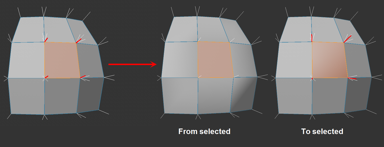
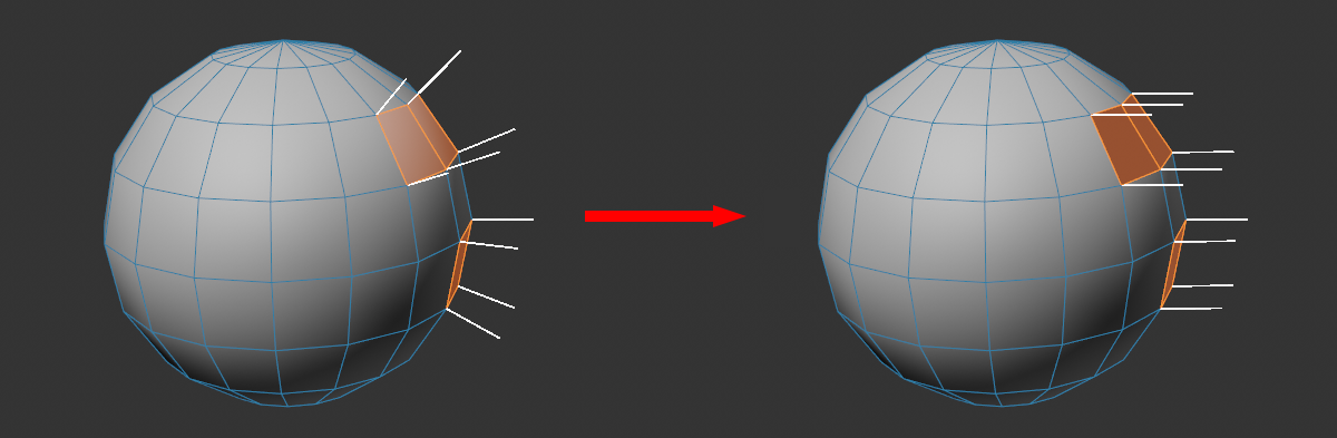
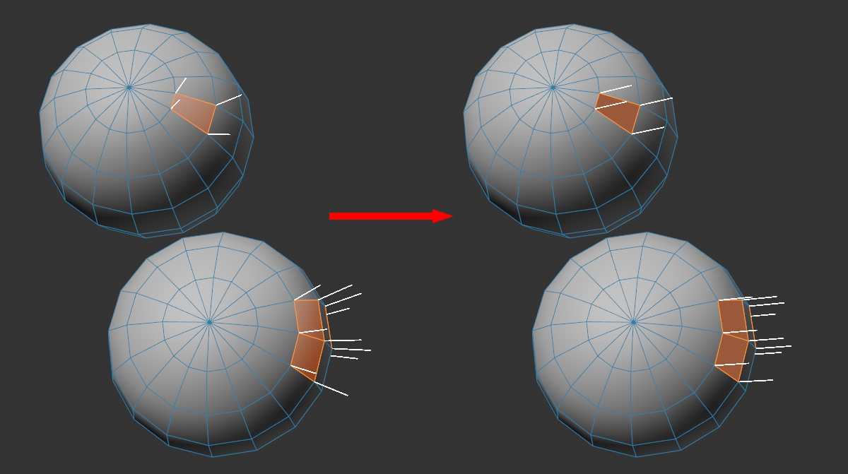
Here you can see a selected polygon, the corresponding selected vertex normals are marked in red. In addition, there are 3 white vertex normals per point, which belong to the other adjacent polygons.
These two commands do the following per point:
- From selected: The selected vertex normals are averaged and this average normal is taken from the others. In the case of a single selected polygon, all will then be congruent.
- To selected: From the unselected vertex normals, an average will be formed on which the selected one is set. This can be used, for example, to smooth a single polygon loop.
X, Y, Z
This command will rotate all selected vertex normals 180° in the opposite direction (provided the X, Y and Z options next to it are all enabled).
Otherwise, a mirror plane perpendicular to it can be defined by individual axis activation. For example, if you activate only Y, only the Y component of the vertex normal will be mirrored.
Polygon Normals
Vertex Normals
Only Selected
If you want to display polygon and vertex normals, activate the respective option. Optionally, this can be applied only to selected elements.
Commands
All the commands just described in button form are also available as individual menu commands that work exactly as described above (any Space settings that may be present have no function for most commands):
See above.
See above.
See above.
See above.
See above.
See above.
See above.