Reconstruction
The Reconstruction goes a step further than the camera reconstruction (which only generates multiple 3D vertices) in that it attempts to reconstruct the video using a 3D Point Cloud or a mesh. In addition, vertex colors will be used to color the vertices or the mesh in accordance with the footage.
The result of this type of scene reconstruction can, under ideal conditions (see Optimal Footage below), be a dense Point Cloud or a coherent mesh (but actual results often differ because in most cases no ideal footage is available; you will then get patchy and isolated Point Clouds or meshes).
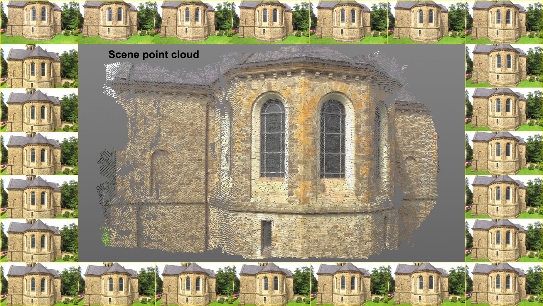 The sequence of images runs clockwise and the corresponding Point Cloud.
The scene reconstruction does not replace a 3D scanner. The Point Clouds or meshes that are created can, for example, serve as orientation in 3D space, for recreating objects and other purposes.
Requirements for scene reconstruction
In order to have a successful scene reconstruction you must always first perform a successful camera reconstruction, i.e., a 2D Tracking was done, after which the camera was reconstructed and the Run 3D Solver button was clicked to complete the process (or everything was done automatically by selecting the Full Solve command from the main Tracker menu). It can also be useful to calibrate the camera and features using the Constraint tag, which will correctly define the reconstructed scene's and Point Cloud's scale and orientation.
When is a camera reconstruction successful? This is the case after the previously described process is completed and a series of Auto or User Features have been added as Child objects to the Motion Tracker object. The Features are important because they will later be used as starting points for the scene reconstruction.
The existing 2D Tracks will then no longer play a role for the scene reconstruction.
Optimal footage
The optimal footage with which the scene reconstruction works as the following characteristics:
- High level of image sharpness with as little depth of field or motion blur as possible
- Images should be very detailed and have a high number of even, monotone surfaces.
- The sequence of images should depict as many sides of an object as possible in a consistent manner and without large jumps.
- A sufficient number of Parallaxes should be present, which is not the case in footage with strong zoom lenses for example. For the same reasons, footage that consists of a single camera movement is also not suitable.
- Reflective materials such as glass, chrome and wandering specular highlights in the footage should be avoided, if possible.
- If you want to create your own outdoor footage, it helps to do so under cloudy conditions in order to have a more even, diffuse light.
Useful information
- Independent of what the Resampling value is in the Footage menu, the scene reconstruction will always use the full video resolution (if you haven't defined a different resolution).
- Tracks serve as starting points from which neighboring regions will be reconstructed.
- Try to have a uniform, adequate Track depth. The more Tracks that exist, the more starting points there will be and the greater the probability that more regions will reconstructed. The exception to the rule: a single feature can suffice to reconstructs a relatively large, continuous surface.
- Large, uniformly colored regions (e.g., sky) cannot be identified from different camera positions and will therefore remain unconstructed.
Limitations
- Higher values for settings or high footage resolution can require a lot of memory. Internal testing showed that far more than 10 GB can be required.
- Depending on the settings, render times of several to very many minutes may be required.
- A good camera reconstruction is required for a scene reconstruction. If the video quality is not good enough for correctly calculating a camera reconstruction, the scene reconstruction that uses it as a base will not turn out particularly well.
- Regions that are not seen by the camera can, of course, not be reconstructed accurately. The same applies for regions in which no or too few 3D features were calculated.
How it works
The algorithm that is used is complex and will only be described here in short (since the parameter naming will otherwise be incomprehensible when patches and cells are explained). Fortunately, the Quality setting adjusts the settings according to its own quality criteria.
Generally speaking, what happens when a scene construction is run?
-
A range of frames will be selected (at least 10; more if the camera movement is faster)
-
Each frame has a camera position (ascertained through the previously executed 3D camera reconstruction)
-
Each of these frames will be divided into square cells using a grid.
-
A 3D point in the scene that is visible from various camera positions has a 2D position in each corresponding frame. This point in turn lies within a cell.
-
The previously completed 3D camera reconstruction has already generated 3D points (the 3D features). These are used to create start patches. Patches are points in space from which the Point Cloud will later be generated. Each patch represents a small, flat surface region.
-
A patch and corresponding cell will be defined for each frame.
-
An iterative expansion process will now take place during which additional patches will be created based on the existing patches (these lie on the 3D surface to be reconstructed).
-
New patches will be assigned to the cells and the cell grid will slowly become more full. The aim is to place a patch in every cell (which rarely actually happens).
-
The expansion of new patches to this point was aimed towards empty cells.
- The expansion process continues until no new patches can be generated that meet the various internal filter requirements (each patch that is created is run through a series of tests; if these tests are not passed, the patch will be discarded) or the cels from all frames have at least one patch.
In a nutshell, the algorithm uses existing 3D vertices (the camera reconstruction features in the first expansion process; the patches of previous expansions in subsequent expansion processes) as a starting position and expands outwardly across a 3D surface. How well this works depends on the footage or scene (as well as the camera reconstruction).
The patches are assigned to a polygon object named Scenepointcloud. Each vertex has a color that was ascertained from the footage that is added to the polygon object as a Vertex Color tag. If desired, a "meshing" can be done, which will generate a polygon surface from the reconstructed vertices.
Here you will find various presets that define the settings below according to the available quality levels. If you can't achieve acceptable results using these presents then you have to assume that you footage is not optimal (see also Optimal Footage).

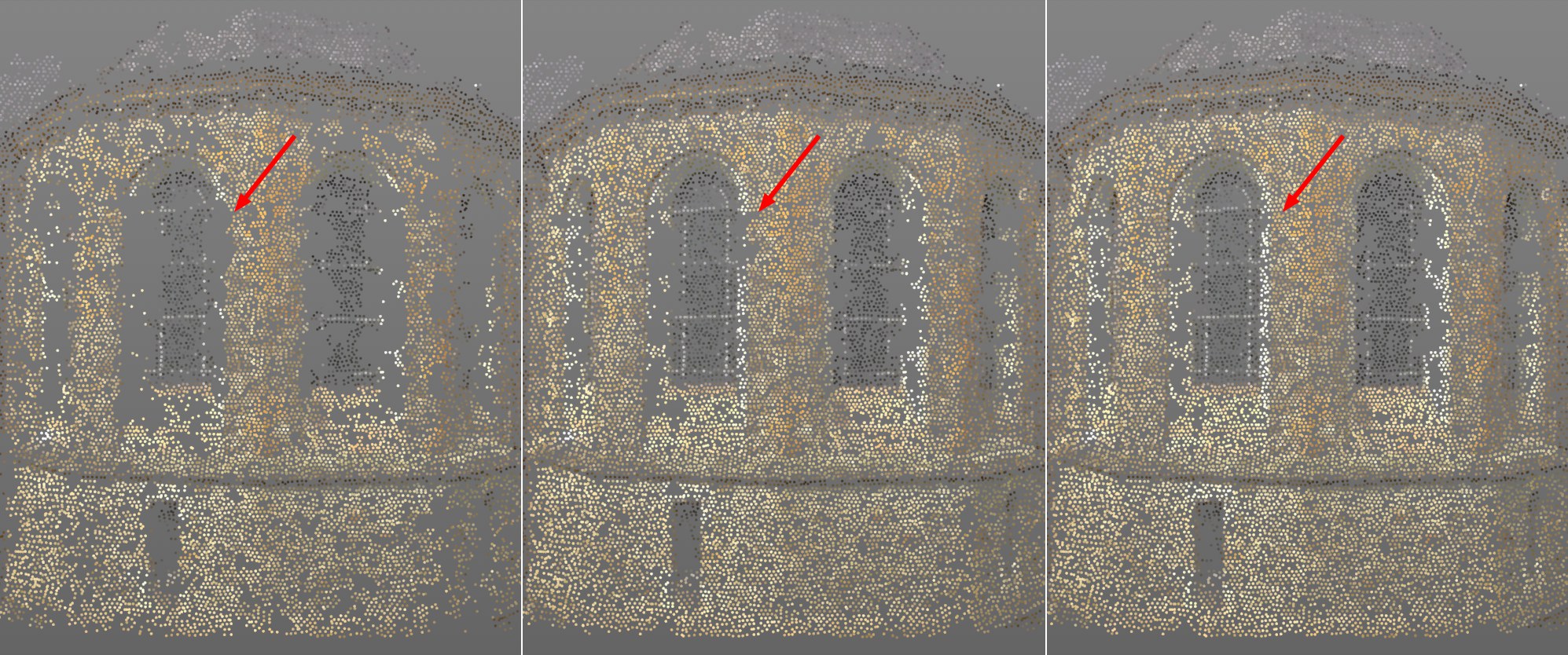 Note how the gaps close with increasing Iterations. From left to right the values 1, 2 and 3, respectively.
If you take a quick look at the order of how the internal processes function you will see that a series of iterative tasks are processed. These are primarily the creation of new patches in empty regions, optimizing and filtering of "bad" patches - and then repeating these processes. This setting defines the number of iterations that should take place.
The higher the value, the fewer "gaps" that the Point Cloud will exhibit and the longer the render times will be.
Two settings that work independently of one another are available for the 3D camera reconstruction (Resampling) and the scene reconstruction that define the resolution with which the footage will be used for reconstruction. The Footage Subsampling setting is used for scene reconstruction.
If the footage should be processed internally with a lower resolution for scene reconstruction, this value should be increased. A value of 0 reflects the original resolution (see next paragraph], 1 half the resolution (in sions, i.e., a square pexel region of 4 pixels will be compiled), etc. The scene reconstruction calculates faster with increasing resolution but the Point Cloud density will abate accordingly.
This setting can be used (e.g., values greater than 1) if you have footage with a very high resolution loaded. This will help reduce render times somewhat.
Note that a value of 0 for the original resolution will not necessarily produce better results than if set to 1. Internally, deviating resolutions will be used, depending on the camera's distance from the patch. The resolution to be defined only applies for an explicit camera to patch distance (which is defined using the "reference camera"). The defined resolution will be used for all distances. If the distances between cameras and patch vary greatly, lower as well as higher resolutions will automatically be applied. However, if the value is set to 0, higher resolutions cannot be applied.
This mechanism makes it possible to more easily compare patches from various distances.
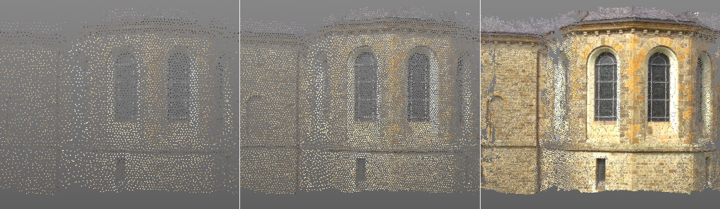 Point Density values from left to right: 3, 5, and 7.
As explained under Function, each frame in the footage is divided into a grid. The algorithm attempts to calculate a 3D point for the Point Cloud in each cell of the grid. Ideally (with optimal footage), this will work (in most cases, however, gaps will remain).
In any case, the Point Density value defines the size of the individual cells of the grid. The larger the value, the smaller and more dense the cells will be and the more dense the Point Cloud will be. The maximum value of 8, the cell size will equal the pixel size, whereby, ideally, one point will lie on each pixel of the footage. Of course the render times will increase accordingly with an increasing Point Density value.
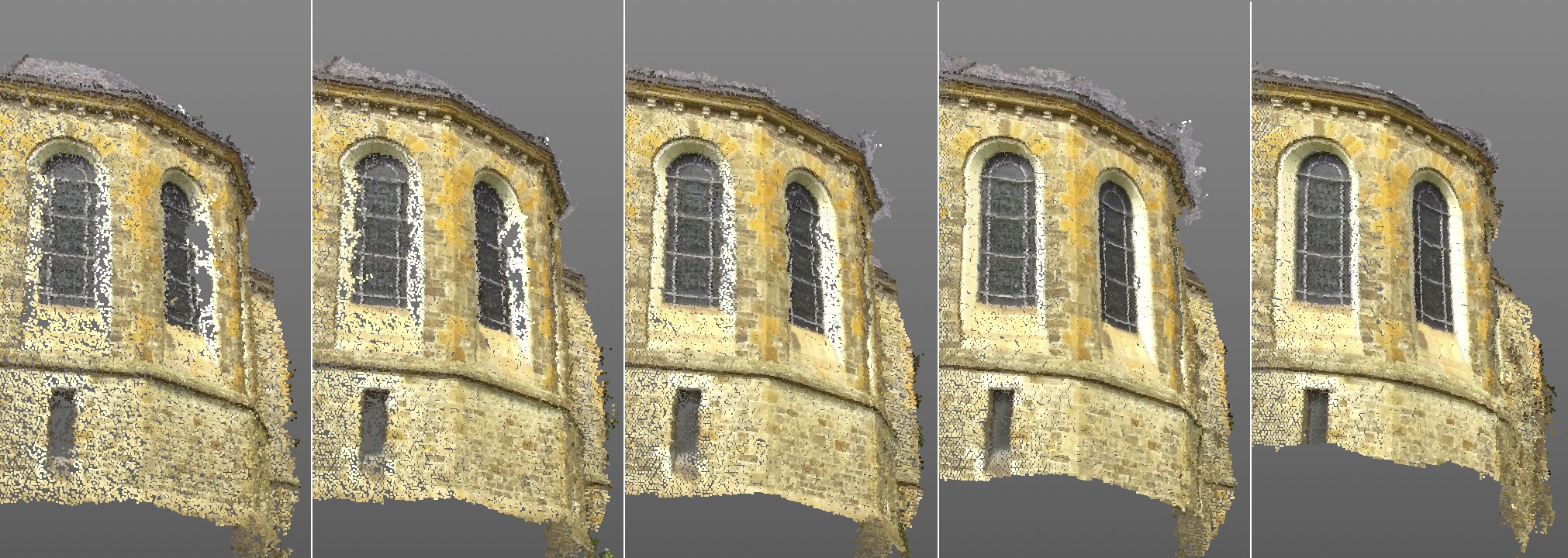 Patch Size values from left to right: 5, 10, 20, 50, 100. Note the increase in quality with the increasing values.
This algorithm tries to recognize small regions in the footage at specific times in order to define and better optimize the position and rotation of the patches. The Patch Size value defines the square size of these regions in pixels. In principle, this value reflects the Pattern Size in the 2D Tracking menu only that it's for scene reconstruction:
Again: Each patch is subsequently represented by a 3D point in the Point Cloud.
Higher values will increase the quality of the Point Cloud accordingly, with correspondingly longer render times. Note in the image above how, for example, the distortion of the window frame and bars improves with increasing Patch Size values.
This value controls a threshold value that uses a patch's pixel variation as a reference. If no real changes take place within a patch's surface, i.e., if it is basically monotone, without high contrasts, a higher Min Texture Detail value will prevent a patch from being created (= no reconstruction at this location).
The purpose of this setting is to prevent patches being created in regions with low texture details (e.g., constant blue sky) by carefully increasing this setting's value. Such regions are very difficult to process and are therefore prone to error.
If you have footage with a high level of texture detail, increasing this value can lead to improved quality for the Point Cloud.
To sum it up, higher values lead to fewer but higher-quality patches/reconstruction points; lower values create more but lower-quality patches/reconstruction points.
The default value of 0.5% should be good enough for most footage.
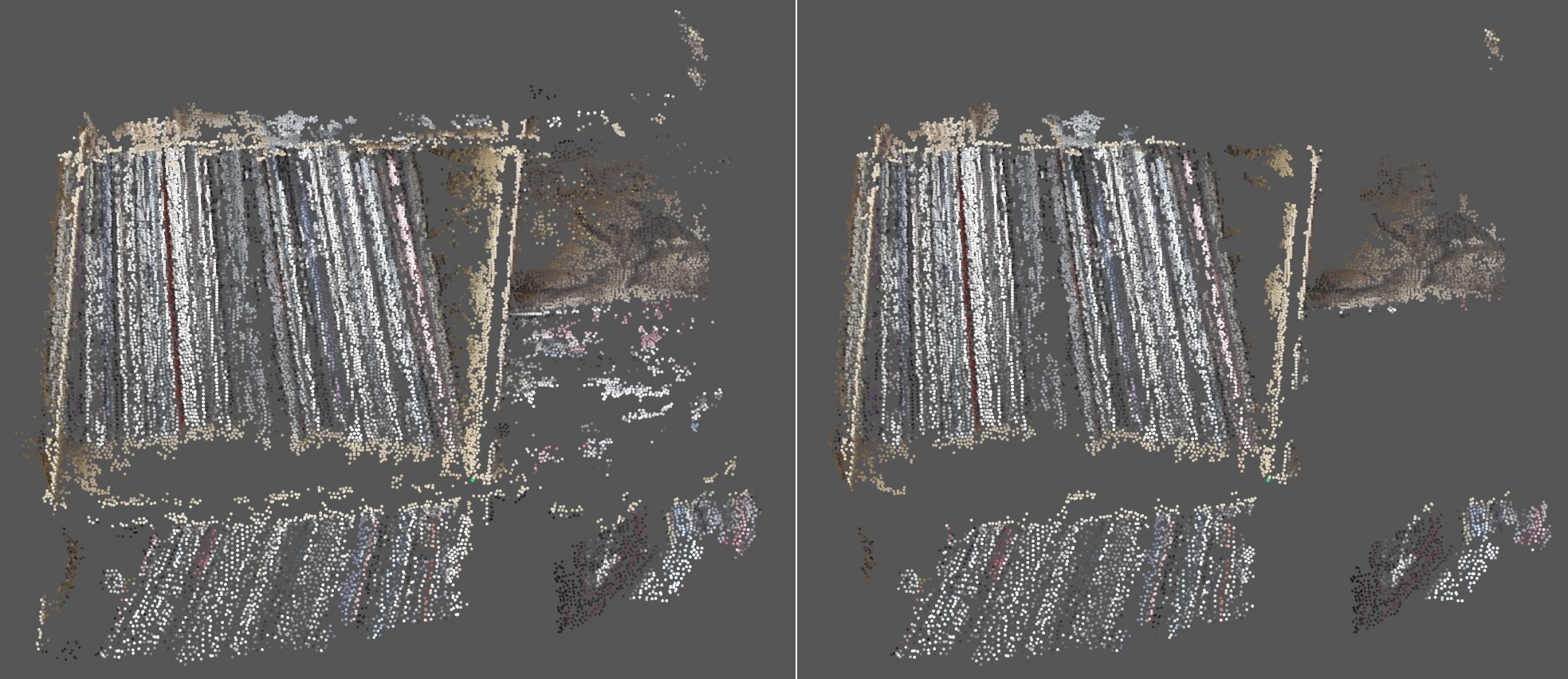 Filter Small Groups disabled at left, enabled at right.
If this option is enabled, the scene reconstruction will try to remove small, isolated patch regions. Note in the image above how many small, isolated point clusters were filtered out.
The effectiveness of this setting, however, depends a lot on the footage and can therefore also be disabled since patches can end up being removed unnecessarily.
Which angle is affected? Imagine a straight line between the first camera and the patch and between the second camera and the patch: both lines meet at the patch. The angle between these lines is the angle that is affected.
Patches are processed from different camera positions (those from the camera reconstruction). This setting ensures that a minimum angle between the cameras is maintained to prevent patches from being processed by two neighboring cameras that have possibly not moved (the patch will be nearly identical).
The default value works well for most footage. For videos in which the camera moves only very slightly it can help to lower the value slightly. This will, however, make the reconstruction less precise. Don't be fooled if the view fills up with patches and reconstructed points when lower values are used - quantity does not always equal quality.
To sum it up, higher values lead to fewer but higher-quality patches/reconstruction points; lower values create more but lower-quality patches/reconstruction points. Values that are too high will result in no Point Cloud being created at all.
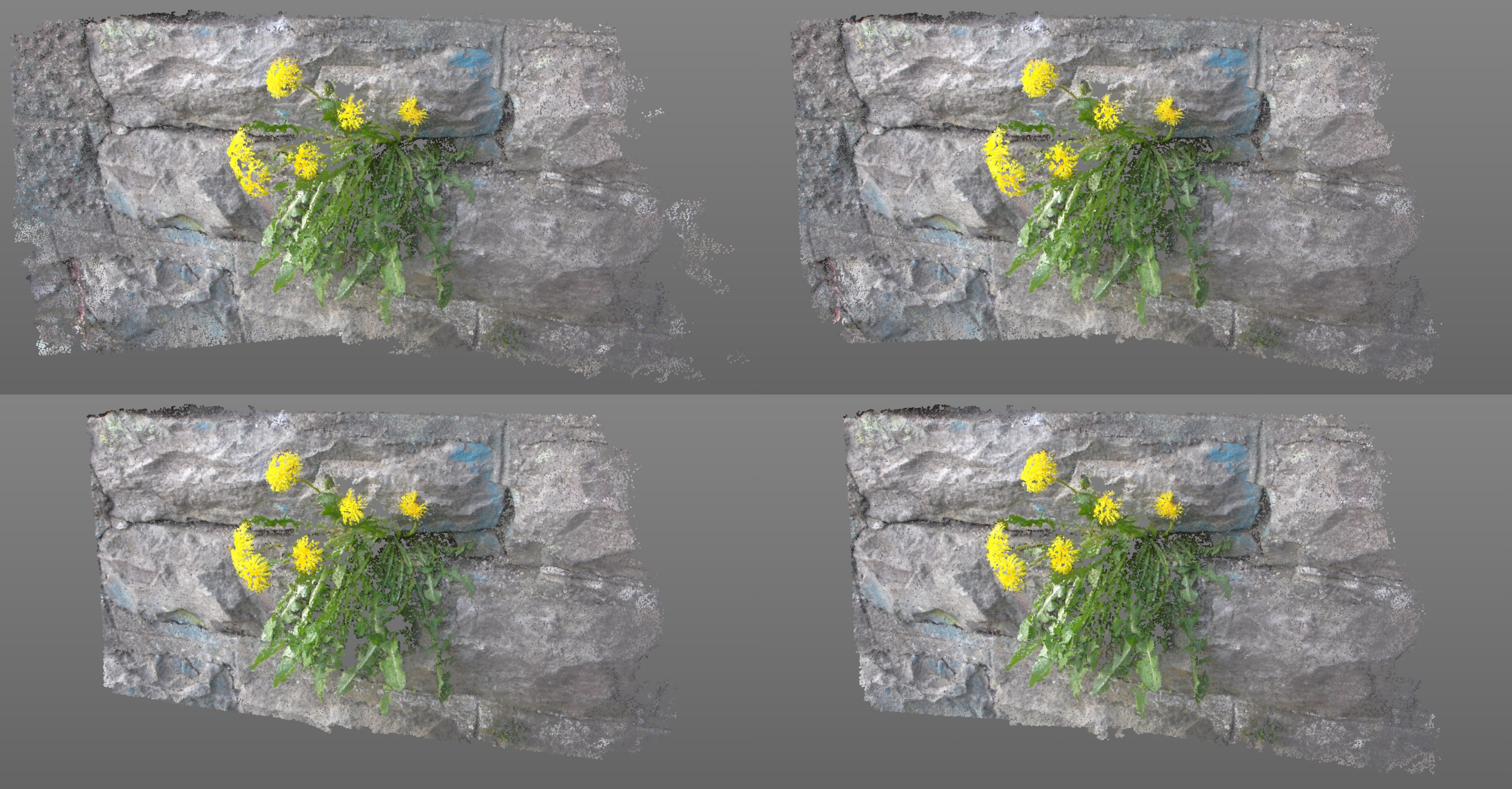 Different values will have the effects shown above. Clockwise from the top left: 2°, 5°, 10° and 15° Min Angle values.
After the settings in the Advanced Settings menu have been defined, a polygon mesh can be created using these points.
Both settings have a similar effect.
With increasing values, these settings will attempt to replace larger triangles with smaller triangles that cover the same surface.
Faulty surfaces will be averted, if possible. If very large values are defined, correspondingly less mesh will remain, depending on the scene.
The Photometric Weight setting works a little smarter than the Area Weight setting because it also uses the footage information.
If a scene reconstruction has already taken place, i.e., you've already clicked on the Create Point Cloud button, this data will be used to generate a corresponding polygon mesh. The Area Weight and Photometric Weight settings can be changed at any time and clikcing on Generate Mesh will generate a new mesh without having to perform a completely new scene reconstruction.
If no scene reconstruction has taken place, this will be done and the mesh will be generated. The polygon object's individual points will correspond to reconsructed 3D positions in space.
It's recommended to first generate a point cloud until you're satisfied with the density and coverage before turning your attention to the mesh.
Tip: Assign a Phong tag to the polygon mesh to smooth it.
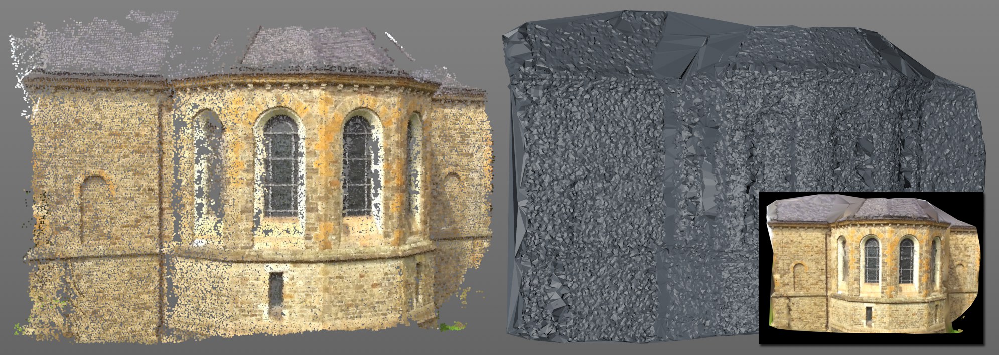 The mesh that was generated using the Point Cloud at the left. The mesh at the bottom right was assigned a Vertex shader in combination with a Vertex Color tag (alternatively it can be textured directly with the footage using the Camera Mapping tag).
Problematic regions in the mesh contain gaps in the Point Cloud. These will initially be closed, regardless of their size, which can lead to very large triangles being created and in turn does not look very good. The previous two settings can be used to lessen this effect.
Clicking on this button starts the scene reconstruction. The result, if successful, will be a scene point cloud with a Vertex Color tag (in which each color of each point in the footage is saved).
Depending on the footage and the settings, the calculation can take a few to several minutes to complete.
This button will be grayed out if one or more prerequisites are not met, for example:
- no camera reconstruction has been done
- the footage was not found