Symmetrize
![]()
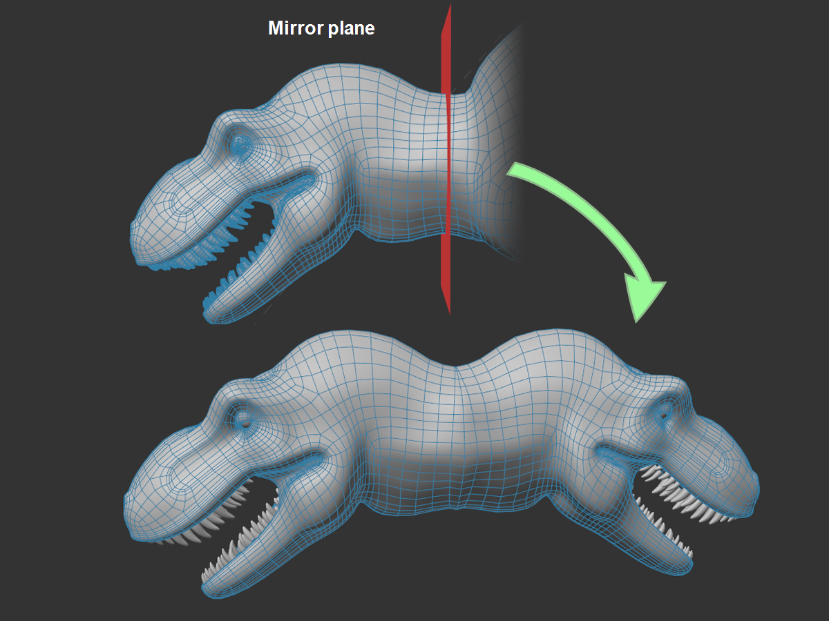
This command allows you to mirror selected objects by means of a mirror plane to be defined and, if desired, to connect them to the initial geometry by merging points that lie on top of each other.
When calling the command, you must be in one of the component modes; in addition, selected objects must be editable. A component selection is not necessary, the complete mesh will always be mirrored.
Options
Type
Here you can choose between Planar and Rotational symmetry (s.a. Type) with which to duplicate.
Link with HUB
If this option is activated, the corresponding symmetry plane settings are taken over from the Link to HUB settings (![]() Symmetry). Otherwise, some of the settings there are shown here and can be defined independently.
Symmetry). Otherwise, some of the settings there are shown here and can be defined independently.
Direction
This setting is displayed when the Link with HUB option is enabled. It defines which side of the symmetry plane should be mirrored. For example, for + to - the positive half will be mirrored.
Cut along plane
If you want to cut selected objects at the mirror planes - e.g., to be able to connect the two halves exactly - activate this option. Otherwise the geometry will simply be mirrored without any additional changes being made. If the mirror plane does not cut the geometry, this option will have no effect.
Remove outside
First you have to define what "outside" is. Take a brief look at the X, Y and Z parameters below. Here, for example, + X to - X can be defined which means that everything on the positive side of the X axis will be mirrored. "Outside" here is then the negative side.
So if Remove Outside is enabled, all geometry on the corresponding side of the mirror plane will be removed. If disabled, a simple mirroring will take place that can easily result in intersecting geometry.
Weld Seam
When cutting the object at the symmetry plane, this option decides whether the points mirrored there, which then come to lie on the corresponding ones of the source geometry, should be merged (option enabled) or remain separated (option disabled).
Tolerance
This setting works together with the previous option Weld Seam and defines the distance up to which from one another points may be merged into one (see also![]() Optimize, option Tolerance).
Optimize, option Tolerance).
Dissolve
If the option is enabled, points and edges created by the mirror plane cut will be removed.
Space
Here you can define where the mirror plane should be placed. These settings are similar to the symmetry settings (see Space).
-
Local: the mirror plane is located at the origin of the selected object's coordinate system. If multiple objects are selected, an average coordinate system will be calculated at whose location the symmetry plane will be placed.
-
Global: the mirror plane is at the world origin.
-
Workplane: the work plane is used as the mirror plane.
-
Custom: with Position and Rotation (these in the world coordinate system) the mirror plane can be freely placed and aligned.
Position/Rotation
This allows the mirror plane to be freely positioned and aligned if Space is set to Custom.
X, Y, Z
Once you have defined the position/alignment of the mirror plane with Space, you can use X, Y, Z to define the half to be mirrored. +Y to -Y means that the positive Y axis halves will be mirrored.
Up to 3 mirror planes can be defined according to the 3 dimensions - although in most cases one is sufficient (most objects are symmetrical only with respect to one plane: e.g., a car body). Rotationally symmetrical objects such as a baseball bat will have 2 mirror planes.
Radial settings
With the Radial type setting, you will find the specific radially symmetrical settings described below (partially only if Link to HUB is disabled).
Axis
Specify the radially symmetrical rotation axis here (for details see Axis).
Rotation offset
This allows the radially symmetric mirror planes to be rotated about the axis of rotation. Activate Mirror to see an effect.
Slice Count
Here you can enter the number of sections within which radially symmetric multiplication is to be performed.
Mirror
If this option is activated, an additional mirror plane will be assumed at the center of each pie slice, which mirrors planar symmetrically per pie slice (s.a. Mirror).
For the special case that you have different geometries in the individual sections, you must define here which section is to be duplicated - others will be ignored:
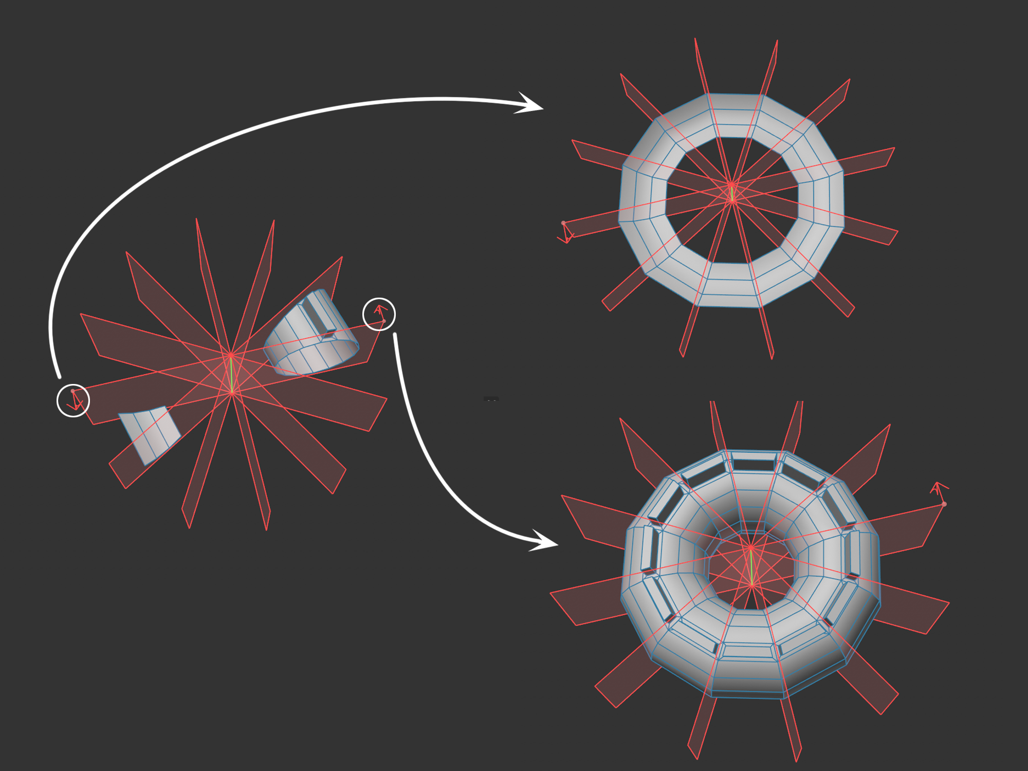
To show the layer preview, activate Show Layers in the global Symmetry settings. You will then be shown by arrow (highlighted above) which is the defining section.