Symmetry
![]()
General
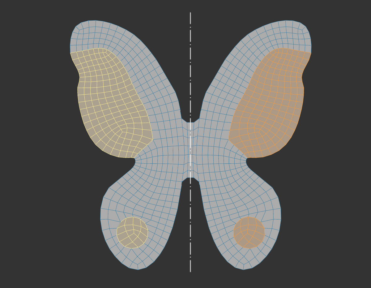 Mirrored selections are displayed in yellow.
Since Cinema 2023, there is a globally effective symmetry system. You may remember the tools such as the Sculpt brush that each had their own symmetry settings. The long-term goal of this system is to centralize all of these specific settings (i.e., the Symmetry settings in the Mode menu and in the layout of the butterfly icon), which will make it possible to enable or disable the common symmetry settings globally. The most important tools such as the mesh modeling tools, several of the spline modeling tools, the Sculpt brush and the paint tool already support the new version.
The symmetry system works both when creating symmetrical objects (previously the ![]() Symmetry object took over this task) by means of the modeling tools, as well as for already existing symmetrical objects where you want to edit, for example, the same polygons on the left as on the right side. This even works up to a certain degree of deformation, to the point at which the symmetry of the original, non-deformed object can still be recognized (see its Topology settings).
Symmetry object took over this task) by means of the modeling tools, as well as for already existing symmetrical objects where you want to edit, for example, the same polygons on the left as on the right side. This even works up to a certain degree of deformation, to the point at which the symmetry of the original, non-deformed object can still be recognized (see its Topology settings).
The symmetry - which, by the way, works as a mode - is mainly determined by means of a symmetry plane (Type Planar), on the basis of which it finally works by mirroring.
By activating the option Show Planes, symmetry planes can also be shown in the view.
This symmetry plane can be positioned freely, but usually planes corresponding to the axes of the local or global coordinate system are used. It's also possible to define the workplane as a symmetry plane. Additional options will be described with the respective settings.
Selection previews (also called virtual selection) are displayed mirrored when symmetry is activated. Selections on the mirrored sides will be colored. This makes it possible to quickly see where the tool was applied.
The global symmetry settings
This window is the global dialog where you make the symmetry settings. Note that several special settings are possible depending on which tool is active. The Sculpt brushes, for example, still have point symmetry settings that the Paint tool does not have.
The window behaves as follows depending on the switched drawing nail icon:
-
Activated: The window remains open until you actively close it yourself. If you want to permanently place the Manager in the layout, this Pin icon must be activated.
-
Disabled: The window closes as soon as you click anywhere outside. This also applies if you have the Manager included in the layout.
Operation
For operation of topology symmetry see Operation here.
This command switches the symmetry on and off globally by toggling the Symmetry option in the Symmetry settings. This works especially fast if you apply a keyboard shortcut to the command.
Limitations
-
Sculpting brushes no longer have individual symmetry settings. These are defined globally in the new Symmetry System.
-
For very complex and large meshes (more than 100000 polygons), performance may be affected.
-
Layer and line intersection, as well as some polygon pen functionalities are not supported when using topology symmetry.
-
Occasionally, tools may not strictly obey the symmetry rules. This mainly happens with components that lie on the symmetry plane (e.g., Flip Edges, for an edge that is also a cut edge for a symmetry plane, will produce a non-symmetrical result. These are rare, undefined cases, which are a limitation.
Settings
Symmetry
Here you switch the symmetry effect globally on and off. Alternatively, this option can be modified using the ![]() Enable Symmetry command (assigning a keyboard shortcut is the fastest method).
Enable Symmetry command (assigning a keyboard shortcut is the fastest method).
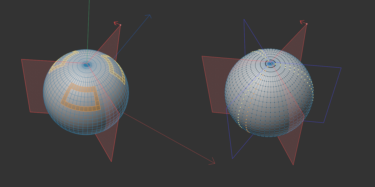
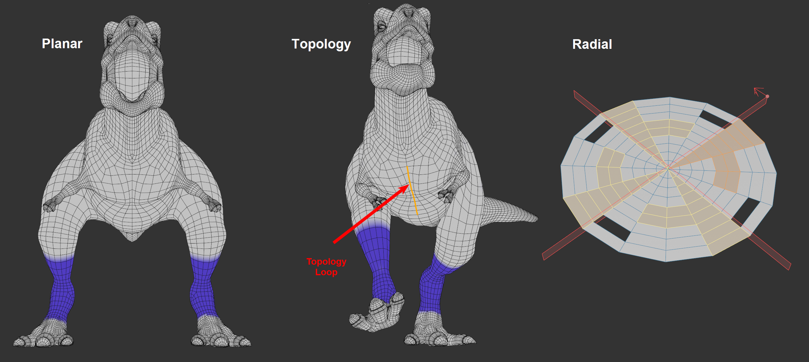 At left and center the left leg painted blue, left with type Planar for a symmetric object, center Topology for an asymmetric object. Right Type set to Radial with radially symmetrical selection.
3 different modes:
-
Planar: Symmetry is created using an adjustable symmetry plane. This works best if you create a new object or an existing object is already symmetrical.
-
Topology: With this type (for Operation see ibid.) the symmetry is determined on the basis of an edge or polygon loop defined by you. This also includes areas that are actually not symmetrical to each other - but once were, for example. Take a look at the deformed T-Rex at the right of the image above. The original model used to be symmetrical but was deformed by joint weighting. Nevertheless, when a leg is painted, for example, the other will be colored correctly of symmetry is enabled.
-
Radial: This type provides you with a radially symmetrical mode of operation. This works best with radially symmetric objects, but can be used with adjustable tolerances for other types of objects as well.
Show levels
If you want to show symmetry planes or topology loops in the view, activate this option. For planar symmetries, the displayed symmetry layers will adapt in size to the bounding box so that these will always be visible.
Context
Depending on the tool, different symmetry settings may result. Sculpt brushes have somewhat different settings than other Mesh tools. In certain cases it can be helpful to temporarily switch to Modeling, for example, to make the fitting settings available (imagine, for example, that you're working with a Sculpt brush but want to quickly subdivide via a Subdivide command).
In most cases, however, it is sufficient to define Automatic here.
Planar settings
The Planar settings define where the symmetry plane should be placed and aligned.
X, Y, Z
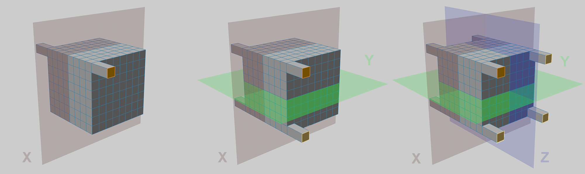 The polygon at the top left has been extruded, from left to right: X, X and Y, X and Y, and Z as symmetrical drives.
If with space the position and orientation of the symmetry planes can be defined, X, Y, Z define symmetry planes perpendicular to the axes, respectively.
Thus, up to 3 symmetry planes can be defined according to the 3 dimensions - although in most cases one is sufficient (most objects are symmetrical only with respect to one plane: e.g., a car body). Rotationally symmetrical objects such as a baseball bat will have 2 symmetry planes.
Here you define the coordinate system for the symmetry planes - these always run through the origin and perpendicular to the axes activated at X, Y and Z. The coordinate systems orient themselves according to:
-
Global: world origin.
-
Local: at the origin of the selected object, in case of multiple selected objects at their average multi-selection axis.
-
Workplane: work plane origin.
-
Custom: the point defined by position/rotation.
Rotation/Position
If you have selected Custom for Space, you can freely define the symmetry plane position with Rotation and Position.
Select object
By clicking this button you can select an object, its coordinate system position will then be entered at Position/Rotation.
Imagine you are working with an object that appears to be symmetrical but actually has slight deviations from ideal symmetry. If the Symmetry System were to now assume perfect conditions, the components would not be found on the other side of the symmetry plane. To prevent this from happening, the following settings can be applied.
-
Clamp: If the option is disabled, simply the closest point (to the ideal symmetry) is considered as the symmetric "partner". If this option is enabled, the following settings will be made available:
-
Tolerance: The symmetrical "partner" may have at most the distance set here (to the ideal symmetry) to be considered a symmetrical point.
If the point of an edge or polygon deviates in the way just described, so that it is not recognized as a symmetrical "partner", the associated edge or polygon as a whole is also considered to be non-symmetrical.
Topology settings
With the Topology type, symmetry is determined using an edge or polygon loop that you define. Regions will also be included that are not symmetrical in 3D space - but were. Type).
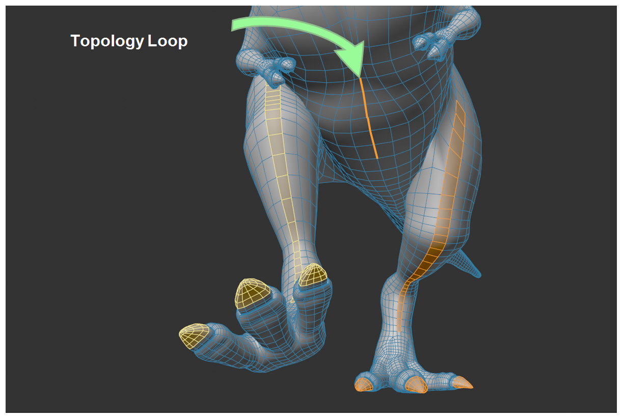
How is a symmetrical component detected here? Put simply, the algorithm will start at the loop and will run perpendicularly to the topology in both directions. Components that lie on a point on the loop 7 edges away in the opposite direction will be seen as symmetrical. Their position in 3D space will not play a role.
This works well as long as the topology is the same on both sides. As soon as irregularity comes into play, this will no longer work. Such irregularity can, for example, be points that have a different number of neighboring points, which will not be classified as symmetrical, including all polygons.
Note that topology symmetry also works with multiple selected objects and also objects with multiple islands. A prerequisite is that each object or each island has its own defined loop.
By the way, the loop will be highlighted if you enable the Show Layers option.
Operation
Proceed as follows:
-
You must first select the loop that defined the previous symmetry in edge or polygon mode. Note that you don't have to select a complete loop - most often a small section will suffice. However: The longer the loop the better the topology symmetry can work.
-
Click on Update Topology Loops. The loop will be saved in a special Selection tag named "Symmetry Selection".
-
Under Loop Mode, select the component loop you defined under "1" and start working.
Enable Topology Loops
Click this button to save the current edge or polygon selection for topology symmetry in a symmetry Selection tag. This is required for the Topology Symmetry to work.
Loop mode
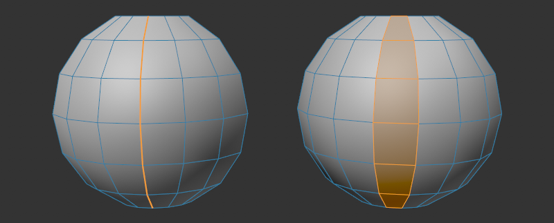
Depending on how your object is modeled, the symmetry can be defined by an edge loop (figure on the left) or a polygon loop (figure on the right). You can make the corresponding selection here.
Radial settings
With Type set to Radial, the number of radial sections can be defined around a given axis, in which radially symmetrical elements are ascertained in each case (in order to select them or to weight them per vertex map, for example).
An imaginary cylinder with the number of pieces defined under Number is placed along this axis. Radial symmetrical elements are searched for the sections each at the same height:
 On the left, radially symmetrical selection, on the right, a point selection with the Mirror option additionally activated.
In this example, axis YZ and Space Local were chosen, which places the axis of the sections exactly on the object Y axis. A selection made on one piece, for example, is transferred to the others.
For XY and ZX, it would then be the X-, respectively the Z-object axis - which, however, would lead to non-optimal results for the mapped Y-rotationally symmetric object. Thus, the axis corresponding to the first letter of the option is used in each case (while the second letter indicates the axis of the - first - radial symmetry plane spanned between these two).
Rotation offset
This allows you to rotate the radial symmetry planes (visible, by the way, when you activate Show Planes ), around the axis indicated above. This can be useful if it is to be adapted to existing geometry.
Source Slice
This setting is intended for the ![]() Symmetrize command (it can take the settings from here). The Source Slice is marked with a red arrow in the view. This slice is then duplicated via Symmetrize (cf. Source Slice there).
Symmetrize command (it can take the settings from here). The Source Slice is marked with a red arrow in the view. This slice is then duplicated via Symmetrize (cf. Source Slice there).
Slice Count
Use this to define the number of pieces around the axis.
If this option is activated, an additional mirror plane is assumed in the center per slice, which reflects planar symmetrically per slice (s. image above). This layer is displayed in blue (visible if you activate Show Layers ).
If this option is deactivated, only radially symmetrical mirroring is performed.
Space
Here you set the coordinate system for the axis of radial symmetry- The coordinate system is oriented to the:
-
Global: world origin.
-
Local: at the origin of the selected object, in case of multiple selected objects at their average multi-selection axis.
-
Workplane: work plane origin.
-
Custome: the alignment defined by position/rotation.
Restrict/Tolerance
See Restrict/Tolerance for the Planar symmetric settings.
Sculpt brush settings
The previous Sculpt brush symmetry settings (then in the Symmetry Brush tab) are now also displayed here in the global symmetry settings. These are:
Radial
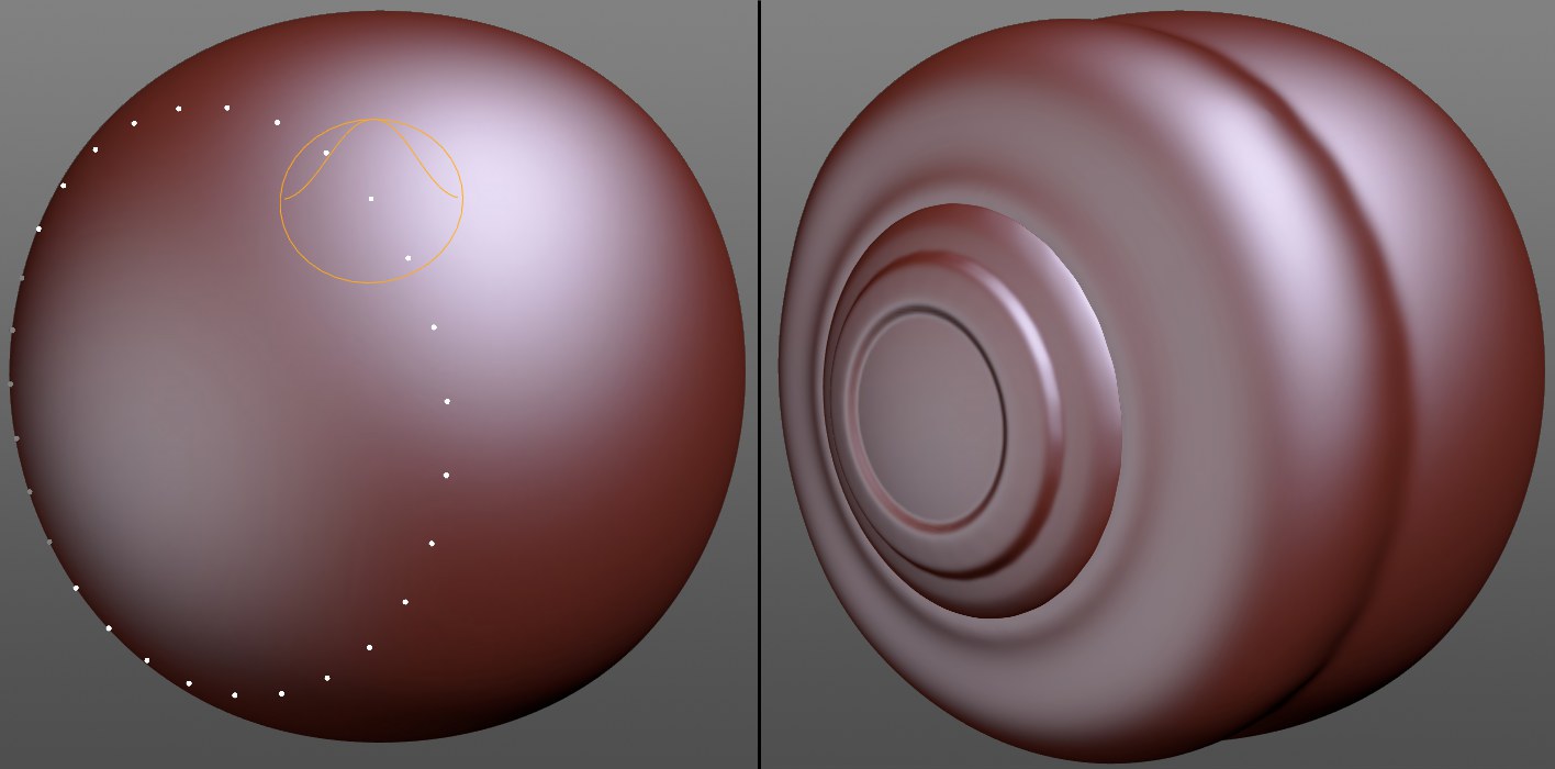
 Such brush strokes are possible, for example, with radially symmetrical reflections. The radial symmetrical center point can be positioned freely. next option)
If the radial symmetrical effect, i.e., rotational dependent, depict spacial repetitions, this option should be activated. The brush stroke will then be duplicated around specific axes, depending on the setting. At the bottom of the dialog window you will see a preview of the effect that gives you an impression of how the brush will behave.
Mode
X, Y, Z

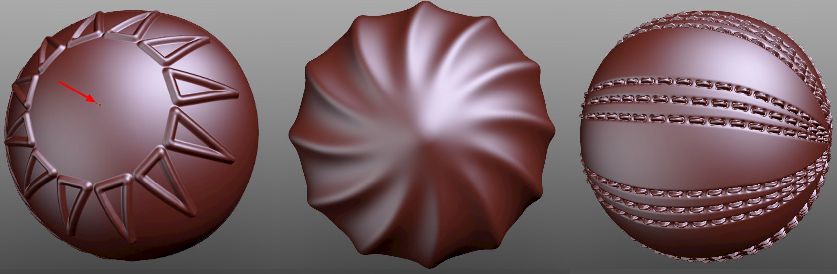
In these modes, a circular distribution of brush effects is made around the set layers. The distance between the cursor at the beginning of the brush stroke and the center point axis is used as the radius. As long as the cursor (with LMB pressed) lies over the Sculpt object, the radial symmetrical positions of the preview will be displayed. If the cursor is moved to a location where the radius brush stroke comes to rest outside of the object, the object center point (marked in the image) will be displayed (note: the object axis can no longer be moved if a Sculpt tag is applied.
Point
Custom Center Point
If you have set the Mode to Point, you can use this option to define the center of the radially symmetrical brush strokes with a right mouse click.
Number of strokes
Here you set the number of brush strokes to be applied simultaneously.
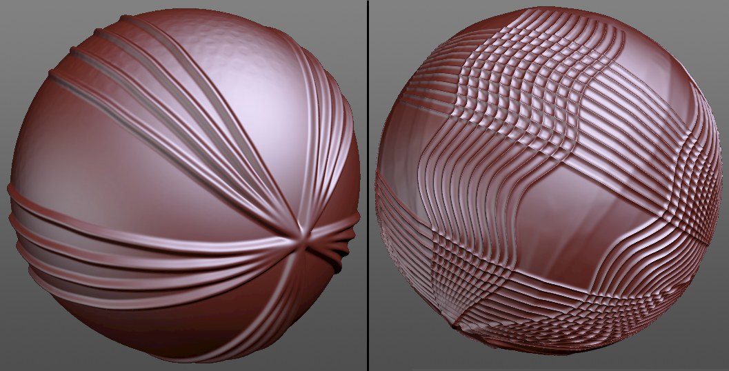
With a high Stroke Number, rotationally symmetrical shapes that merge into one another can also be realized well:
Gap Rotation
This parameter can be used to insert gaps in the otherwise evenly distributed radially symmetrical brush strokes if you define values above 0°. Brush stroke groups (each with Stroke count) will be created according to the following scheme: For example, if you define a brush stroke group uniformly at 45° followed by a 45° wide gap, then again a 45° brush stroke group.