Axis
The modeling axis settings described here will affect each newly selected element.
The Modeling Axis tab is described here and is available for each of the following tools: Move, Scale, Rotate, Live Selection, Rectangle Selection, Lasso Selection and Polygon Selection.
You can adjust the position and orientation of the modeling axis interactively.
Here you can define the position of the modeling axis. For a single object, the following applies to the modeling axis for position:
The modeling axis is located at the origin of the world coordinate system.
The modeling axis is set to the object axis of the object defined in the Object field below. If this field remains empty, the currently selected object will be used.
The modeling axis is always located in the spatial bounding box center of the selected elements (see also Selected points below).
The modeling axis is located at the object axis of the top-most object in the hierarchy.
The modeling axis corresponds to the object axis of the parent object, i.e., the object that is directly above the current object in the hierarchy.
The modeling axis lies at the center of the bounding box of the selected objects. The bounding box is the cuboid into which all selected objects fit. You can use the X, Y and Z sliders to move the modeling axis steplessly within the bounding box.
The modeling axis is located at the center of all object points (including those that are not selected).
The modeling axis will be arranged at the center of the view.
If you want to freely position or rotate the modeling axis using the Rotate/Move modeling axis commands, the system will switch to this mode.
This option is used to move the modeling axis to the position average of the selected elements (unlike Selected above, where the bounding box center is used).
Defines the orientation of the modeling axis. Depending on which mode you select, the modeling axis will point in the same direction as:
Defined by the Orientation setting. In other words, the Orientation setting (see above) will also be used to control the modeling axis orientation.
The world axes, the object’s axes, the axes of the object that is at the root of the hierarchy, and the axes of the object’s immediate parent respectively.
The average direction of the Normals of the selected polygons (the modeling axis points with its Z axis).
The camera.
If this option is enabled, the modeling axis will temporarily retain its position after being moved or rotated. For example, suppose Axis is set to Object (in this mode, the modeling axis will be positioned at the object’s origin). You select some polygons and move them to a new position by dragging an axis arrowhead. The modeling axis will move along with the polygons while you are dragging the polygons to their new position. If Retain Changes is enabled, the modeling axis will stay where it is when you release the mouse button. If the option is disabled, the modeling axis will immediately jump back to the object’s origin as soon as you release the mouse button.
If this option is enabled, each of the selected elements (points, edges, polygons and separate selections) will be scaled or rotated around or along the average direction of their Normals.
What you should be aware of:
- This option does not work in conjunction with the Scale or Rotate tools when in Use Point mode
- If the Move tool is enabled you can drag along the Z axis to move components along their Normals
- This also works with soft selections in conjunction with the Move tool
If Position is set to Object, you can Drag & drop any object from the Object Manager into this box. The modeling axis will then be positioned at this object’s origin (and will also point in the same direction as this object’s axis system if Orientation is set to Object).
These sliders enable you to offset the modeling axis in the Selected and Bounds modes.
These sliders enable you to offset the modeling axis in the Selected and Bounds modes.
These sliders enable you to offset the modeling axis in the Selected and Bounds modes.
This special rotation band mode helps you avoid Gimbal lock (which is mainly of interest to animators). Instead of going into depth with complex mathematical formulas and explanations we will simply demonstrate how this mode can make creating rotational animations easier.
A simple example problem: Create a Cone and activate the Rotate tool. In the Coord. tab, set R. P to 80°.
Your scene will look as follows:
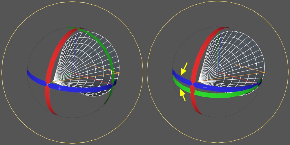 The Gimbal lock at the right needs to be avoided.
Everything looks completely normal. All three bands lie perpendicular to each other. Everything is fine. You can still rotate the object in any direction.
But things only look good on the surface. If you want to animate the Cone (around its long axis), things can get difficult. If you were to create several keyframes, first a rotation key and down the line a second one (after having dragged the green rotation band), the Cone would tumble unpredictably around all axes.
You will see why this happens when you enable the Gimballing Rotation option. The rotation bands now look like the ones at the right of the image above. The green and blue bands almost lie over one another. You can actually see that a correct rotation around the Cone’s long axis will be difficult at best (a correspondingly oriented band doesn’t exist). A classic example of Gimbal lock. This is what we want to prevent from happening and this is what the Gimballing Rotation option helps you do.
Note also the rotation Rotation Order which lets you select a different axis rotational order (PRIOR to animating). One of the available options should fit your needs.
Of course you can still use the traditional method of circumventing Gimbal lock by animating a parent Null Object.
In the Customize Commands… Manager you will find the Gimballing Rotation command with which you can toggle this option.
Note also that the gimbal rotation bands will be disabled when you switch to the world coordinate system.