Tag Properties
Activates the assigned object as Emitter for the Pyro simulation. If you turn off this option ,e.g., by setting keyframes during an animation, the generation of new smoke, temperature, and fuel will stop at that point. However, components of the simulation that have already been generated will remain visible and continue to be simulated until they are resolved.
The object occupied by the tag will be filled with Voxels to ascertain the Emitter area or volume. You can imagine Voxels as perfect cubes whose edge length you can define here as a percentage using the Object Resolution. The Object Resolution refers to the Voxel size parameter that was linked as a Pyro scene on the Pyro output object.
With an Object Resolution of 100%, the Voxel size will also be used to detect the object volume at the Emitter. For smaller percentage values, the Voxels used to capture the Emitter increase in size. This can lead to fine sections of the Emitter object no longer being recognized, although a small Voxel Size is used in the linked Pyro Scene of the Pyro output object. Of course, this can also be used deliberately to generate smoke, fuel or temperature only at the thicker parts of the object.
 Here, a Torus primitive object was used as an Emitter. On the left, a very small percentage value is used for the Object Resolution; on the right, 100% is used. Note how this not only makes the shape of the Emitter clearer, but also causes the simulated gases to take on different shapes with otherwise identical simulation specifications.
 On the far left you can see the object that was used as a Pyro Emitter. The two simulation images next to it each show the same animation frame and otherwise use identical settings. The only difference is the value for Object Resolution. The simulation image on the left uses an Object Resolution of 1%. It can be clearly seen that not all areas of the thin protrusions on the object were used as Emitters. The generation of smoke and heat is therefore concentrated at the center of the object. To the right, an Object Resolution of 100% was used. Even the thin areas of the Emitter object are now reliably detected. Accordingly, more density and temperature will be emitted.
When creating a simulation, pay special attention to the size of the objects to be used as Emitters. Many properties of the simulation depend, for example, on the Voxel Size or the density of the simulated gases. The result of the simulation will therefore change depending on how large the burning area is, for example. For example, a candle flame burns relatively calmly and forms a drop shape. The temperatures of the flame range from about 800 degrees at the wick to about 1300 degrees at the tip. A blazing campfire behaves quite differently visually, but at its core has similar temperatures to the candle flame.
Therefore, first make sure that your object serving as an Emitter has realistic dimensions. Then adjust the value for the Voxel Size in the Pyro settings linked as a Pyro Scene on the Pyro Output object. Relatively speaking, for a spatially small simulation, the Voxels should also be smaller than, for example, for a large-scale explosion. This has to do with the viewing distance. A small simulation is often viewed more closely than a large one, and therefore needs more detail. In addition, it is also important to keep an eye on memory requirements and simulation times during simulation. For a simulation of the same size, smaller Voxel Sizes generally result in more memory requirements and extended simulation times. In addition, any cache files that are used will also become larger. Therefore, always compare which Voxel Size makes sense for the desired effect.
It is also necessary to adjust the Object Resolution on the Pyro or Pyro Fuel tag. This refers to the Voxel size as a percentage and can therefore also be adjusted to the size and shape of the Emitter object. By reducing the Object Resolution, a large Emitter object can therefore also be combined with a small Voxel size in order to save some memory and computing time in the output of density, temperature or fuel. In addition, small values for the Object Resolution automatically ensure a smoothing of the Emitter volume and thus a more homogeneous output of density, temperature and fuel. However, if the percentage values are too small, the volume of the object may no longer be fully detected if, for example, finer protrusions are present there.
Pyro Voxels are generated at the assigned object in a specific temporal intervals. Provided that your object remains static and unchanged in shape, this is not so critical. However, if an object is animated in position, for example, or changed by a simulation or by deformation, for example, the adjustment of the Emitter shape must be faster. Two modes are available:
- Frame Range: By default, the Emitter shape is updated once per animation frame. The number of Emitter shape updates per animation frame can be increased via the Substeps value. This means that even faster-moving objects can still function precisely as Emitters. In this mode, the recalculation of the Emitter position always takes place in the same temporal cycle.
- Continuous: In this mode, the Pyro Emitter is also updated depending on the Substeps value, but Cinema 4D can decide for itself when a recalculation makes sense. The time intervals between the adjustments of the Emitter position, therefore, do not always take place in the same temporal cycle. In general, this mode already gets by with fewer intermediate steps even for moving objects, compared to the Per Animation Frame mode.
 In this example, a ring animated by shifting position from bottom right to top left is used as the Emitter. The upper half of the image shows the Continuous mode with the Substep values 0, 3 and 10 (from left to right). Below you can also see the results with 0, 3 and 10 Substeps, this time in Frame Range mode. There the equally large jumps in the shift of the Emitter area stand out clearly, while even with small substep settings the Continuous mode updates the Emitter area more effectively. By the way, the dark areas here result from the Noise settings, which can be used to influence the distribution of newly created gas within the volume.
If this option is activated, new Pyro data is only generated within voxels that are already active. This prevents the Pyro simulation from spreading. Nevertheless, new voxels can still be created in the outer area of the simulation if, for example, the temperatures there exceed the Temperature threshold.
As there are no active voxels at the start of a Pyro simulation, activation only makes sense once at least the first voxels with temperatures, pressures and density values are available. The active option can then be used to optimize the number of voxels.
This can be used to control the additional number of recalculations of the Emitter shape and Emitter position. This can be useful if, for example, you are working with fast-moving objects that are to serve as Emitters. When these additional calculations take place is controlled by the Substep mode. If the Emitter object is animated in the topology or shape, the Substeps mode Continuous should be used so that shape changes can also be detected between the main animation frames.
Here you select how the assigned object should be evaluated to define the area where steam, heat or fuel should be created. The following modes are available for this purpose:
- Surface: This is the right mode if you want to use polygon objects that are not a closed volume. Think, for example, of a simple plane or a sphere from which some polygons have been removed. In such cases, it is not clearly defined in which area, for example, steam is to be generated. Therefore, a Thickness value is offered in this mode, which can be used to define a distance from the polygons in which the Pyro simulation should then generate the gas. In the case of a plane, the simulation would then perceive it as a cuboid.
The same problem also affects splines. Again, this mode is often the correct choice so that the spline can be evaluated as a tube by the Thickness, which can be used as an Emitter volume.
Of course, this mode can also be used with closed objects if, for example, you deliberately want to create some fire and smoke outside the objects volume.
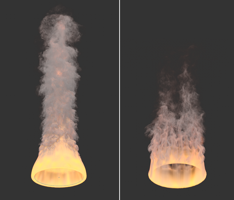 Examples of Surface mode: On the left, a hemisphere open at the bottom has been used as a Pyro Emitter; on the right, a simple circular spline.
- Volume: Use this mode if you want to use a closed object, such as a cube or sphere, as an Emitter. Here, only the interior of the objects is used as Emitter.
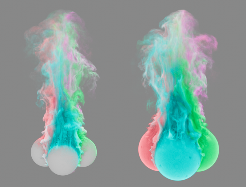 Example of Volume mode: On the left you can see four spheres arranged in a circle, each emitting differently colored smoke as a volume Emitter. The spheres themselves remain visible and are only hidden by the escaping smoke. To the right, for comparison, the same scene, only this time using the Surface mode. The surface area of the spheres is increased for Pyro emission. As a result, the spheres themselves are now enveloped by the newly-emitted smoke.
- Points: This mode is primarily intended for use with particles or matrices, such as those generated by the MoGraph Matrix object or particle groups. For this reason, the Pyro Emitter Tag will automatically use this mode when assigning to corresponding Emitter or MoGraph Matrix objects. However, there is nothing against the use with splines or e.g., polygon objects. In that case, only the points of these objects become areas where Pyro elements are emitted. A spherical volume is formed around the particles, matrices or points, the radius of which can again be set via the Thickness value. As a special feature of this mode, the colors of particles and MoGraph matrices as well as the individual sizes of particles are automatically taken into account. In the case of Thinking Particles, in addition to the colors and sizes of the particles, individual variables can also be created, e.g., for the density, the temperature or the fuel, and evaluated by the Pyro simulation. For this purpose, these variables must be named density, temperature and fuel according to the simulation channels. But data can also be exchanged via the user properties of particles, e.g., to influence the density, temperature or even the colors within the Pyro simulation.
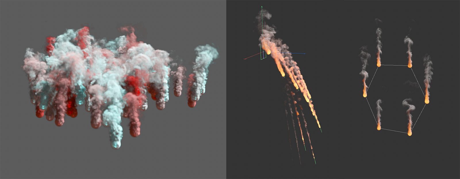 Examples of the Points mode: On the left, a MoGraph Matrix object was colored using a Random Effector. The colors can be adopted for the Pyro smoke. On the right, an Emitter and an n-Side spline can be seen as Pyro Emitters. The final size of the particles is automatically included in the scaling of the surface thickness.
- Dynamic Geometry: This mode is specially designed for deforming objects and for even higher-performance evaluation of vertex maps and color maps. The following image shows an example of this. Please also note that a Velocity in the direction of the surface normal and a noise structure along the UV coordinates can only be be activated in this mode.
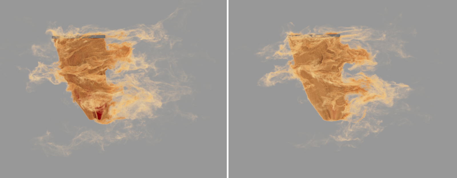 Here you can see a red curtain blowing in the turbulent wind, animated via the Cloth simulation. On the left, the Surface mode was used to emit sand-colored smoke from the fabric. In some places, the emission cannot keep up with the fast-moving fabric, as is particularly evident in the lower part of the curtain. To the right is the exact same simulation image, this time with smoke using the Dynamic Geometry mode. The entire curtain will be covered in newly emitted smoke.
- Sparse Surface/Sparse Volume: These modes work in a similar way to the Surface and Volume modes. The differences to these older modes lie mainly in the internal management of the VDB tree structure, as NanoVDB is used in the Sparse modes. These use a simplified tree structure for voxel management, which can lead to faster processing and reduced memory usage. However, the results are also slightly different compared to the standard modes for Surface or Volume, as shown in the following illustration. This can lead to a change in the simulation and the number of voxels used if you subsequently switch a simulation from Volume to Sparse Volume, for example.
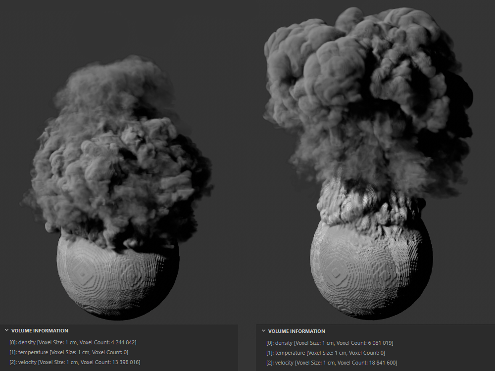 On the left is a simulation in Volume mode, on the right in Sparse Volume mode, with otherwise identical settings. The information displayed below also shows that in this case more voxels are simulated with a Sparse Volume. This effect may also be reversed with other voxel sizes or emitter shapes. This means that simulations can also be created with a smaller number of voxels compared to the older surface and volume modes.
In the Surface, Dynamic geometry and Points modes, this can be used to define a distance on both sides of the object's polygons or a radius around the spline or around the particles or points in which Voxels are still generated for the Emitter shape. The Emitter shape can be enlarged or a Voxel distribution for the Emitter can be created even for non-closed objects.
In the special case that the Pyro Emitter has been assigned to a particle group or one of the older emitters, the Thickness value is automatically multiplied by the Radius of the particles. In these cases, the value 1 is sufficient to use the original size of the spherical particles as the emission volume.
Emission Falloff[0.00..256.00]
This setting is only available for the Surface and Volume modes and can automatically apply a falloff to the density of the Pyro elements generated at the Emitter near the edge of the selected surface Thickness, or near the edge of the volume used. This reduces the total amount of gas emitted accordingly. The following image shows an example of this.
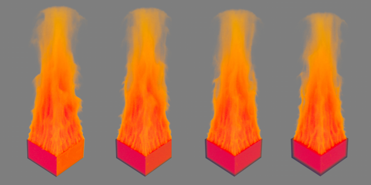 Here, a cuboid is used as the volume for the Pyro Emitter. This is shown here slightly transparent so that the gas emitted directly inside can also be seen. The series of images represents the values 0, 4, 8 and 16 for the Emission Falloff. It can be clearly seen how the gas generated in the cuboid becomes less in the edge region and therefore the gap between the gas and the cuboid becomes larger and larger as the values for the Emission Falloff increase.
This can be used to assign a Vertex Map, a Vertex Color Map or a Polygon Selection by dragging the corresponding tag from the Emitter object into it. An assigned map or selection then specifies in which areas of the object Pyro properties are to be generated. In this way, only parts of an object can be made to burn or steam, for example. In addition, a Vertex Map or Vertex Color Map can also be used with transitions, or intermediate values, to create smooth transitions, for example, between burning and non-burning areas. Note that for Vertex Color Maps, only their Alpha values are used.
 Here, a disc was used as an Emitter. A Random Field generates weights for a Vertex Map tag, which is then used as an Emission Map for the Pyro simulation. As can be seen in the rendering on the right, this results in smoke on the disc only where there are weightings above 0%.
Since the introduction of user properties for particles, these can also be used to control the emission properties. User properties can be created via the simulation settings for particles and configured with different data types and individually assigned names. You can find out more on this page.
To control the emission, data of the floating point type and therefore concrete values between 0 and 1 are required. Simply enter the name of the user property to be used in the emission map field. Only particles with a user property whose value is above 0 will generate Pyro emissions. For values between 0 and 1, the intensity of the emission is reduced accordingly. The full Pyro emission of the properties described below only occurs with the value 1. The following image shows an example of this. There, the X-positions of the particles were converted into values between 0 and 1 using a Data Mapper modifier and stored in the specially created variable X distance from emitter. This X distance from emitter name is then also entered for the Emission Map on the Pyro Emitter Tag assigned to the particle group.
The use of particle properties to control Pyro emissions is further simplified by the fact that you will find a small button behind the input field for the Emission Map, which can be used to directly select the compatible particle properties currently available on the Particle Group.
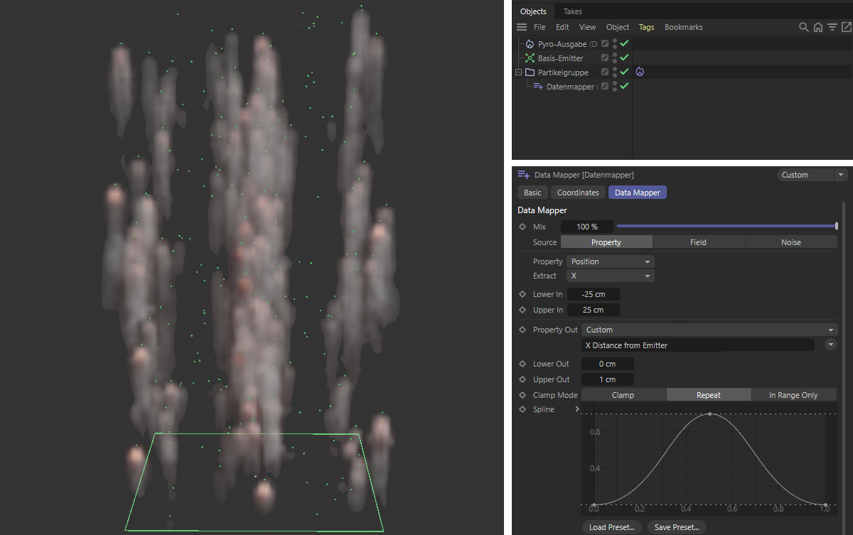 The particles here have an "X distance from emitter" custom property of the Float - Meter type, which is filled with values between 0 and 1 according to the position of the particles along the X axis. The Pyro Emitter tag reads these values and thus varies the emission per particle depending on its X-position.
Since all components of the Pyro simulation, i.e., their density and color, the temperature and the fuel, also have their own assignment options for various maps, user properties and Selection tags, it is possible to individually control where and with what intensity a Pyro component should be created on an object.
This effect is needed for the creation of smoke or steam. Think of the density as smoke or dust emitted from the Emitter. Moreover, this density dust can be generated by fuel that burns. If you want to represent an explosion, for example, you may therefore not need to simulate the density at this point. The smoke can also be assigned colors, illuminated and rendered. In addition, the density can also react, for example, to objects that have a Collision tag (found in the Simulation tags). The swirling of the simulated gases in the air, as well as the influence of gravity, for example, can be controlled via the Pyro Scene settings linked in the Pyro Output object. In addition, the dust interacts with the temperature at the Emitter. The hotter the simulation, the faster the smoke will rise. The velocity and direction of movement of the density simulation can also be affected by the following force simulation objects:
- Attractor
- Force Field (with this, fields can then also act on the simulation)
- Gravity
- Rotation
- Turbulence
- Wind
- Destructor (can be used to limit the simulation volume or to delete parts of the simulation)
This activates the generation of haze, smoke or dust at the object's Emitter.
This setting becomes visible after clicking the Arrow icon in front of the Density Enabled option. By default, the entire assigned object becomes an Emitter. However, this is not always useful. For example, think of a torch or match that should only burn or produce smoke at the tip. You can assign a Vertex Map of the object here. The percentage values within the Vertex Map can be used to individually restrict the use of the object as an Emitter. Where the intensities in the Vertex map are set to 100%, the surface will produce smoke at full intensity. For lower Vertex map values, the amount of smoke will be reduced accordingly. In areas with a strength of 0% for the Vertex map, no more density will be generated. Since the values of a Vertex map can also be animated, e.g., via Fields, variations of the generated density can also be realized.
As an alternative to a Vertex map, you can also use a Vertex Color tag. In this case, the alpha values that were previously created using the Paint tool or Fields are evaluated and multiplied by the color brightnesses from the vertex colors.
Since the introduction of user properties for particles, these can also be used to control the emission properties. User properties can be created via the simulation settings for particles and configured with different data types and individually assigned names. You can find out more on this page.
To control the density, data of the floating point type and therefore specific values, e.g., between 0 and 1, are required. These are then multiplied by the specified density here in the Pyro Emitter tag. Simply enter the name of the user property to be used in the Density Map field. Only the particles where the specified user property is above 0 will then be able to generate density.
The use of particle properties to control pyro emissions is further simplified by the fact that you will find a small button behind the input field for the Density Map, which can be used to directly select the compatible particle properties currently available on the Particle Group.
You can find a simple example of the basic use in the description of the Emissions Map above and also in the following video.
Another example can be seen in the following video. There, a separate property was varied with a Data Mapper depending on the age of the particles and then used to control the density. You can find this scene to try out for yourself under the file icon directly below the video.
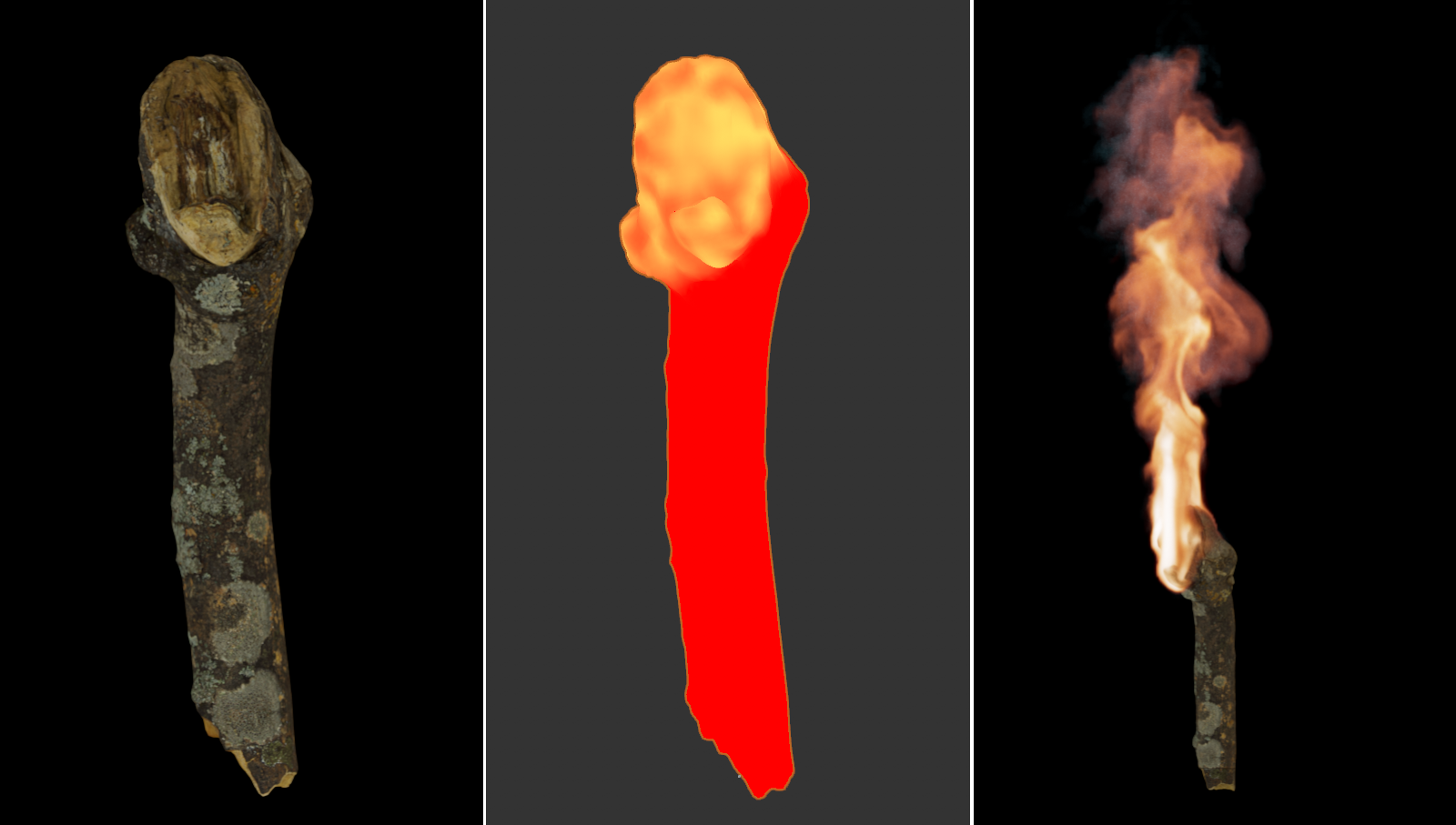 On the left you can see the 3D model of a piece of wood that will be turned into a torch with the help of the Pyro simulation (you can find this piece of wood under the name 'Wood 03' in the Asset Browser). Since the wood should only burn at the upper end, a Vertex Map is created there, which is additionally varied with an animated Random Field. This provides a more natural temperature and density distribution for the simulation. On the far right is the result of the simulation. The Vertex Map was used in the simulations for density and temperature.
Here you define the minimum density of smoke that should be produced at the emitter. By adjusting the Pyro Scene parameters of the Pyro Output object, this steam or smoke can also be automatically dissipated over time, e.g., to limit the height of a rising smoke column. The following Density Add value can be used to generate additional density per second of animation at the Emitter. This difference in the effect becomes relevant if several emitters generate particles in the same area, as Density Add is added to existing Density values in the area of the emitter, unlike Density Set.
Density Set only sets a minimum value for the Density property at the emitter. If other Pyro gases with possibly higher density properties are also present there, their Density values are used for the gas instead.
Bear in mind that the amount of Density can also influence the course of the simulation. ,More smoke (more density) therefore, often also leads to faster speeds and stronger turbulence. Since this smoke dissipates by default over a period of time defined in the Pyro Scene (see Pyro Output object), faster gases cause a dense column of smoke to span a further distance before fraying. The following series of images gives an example of these effects.
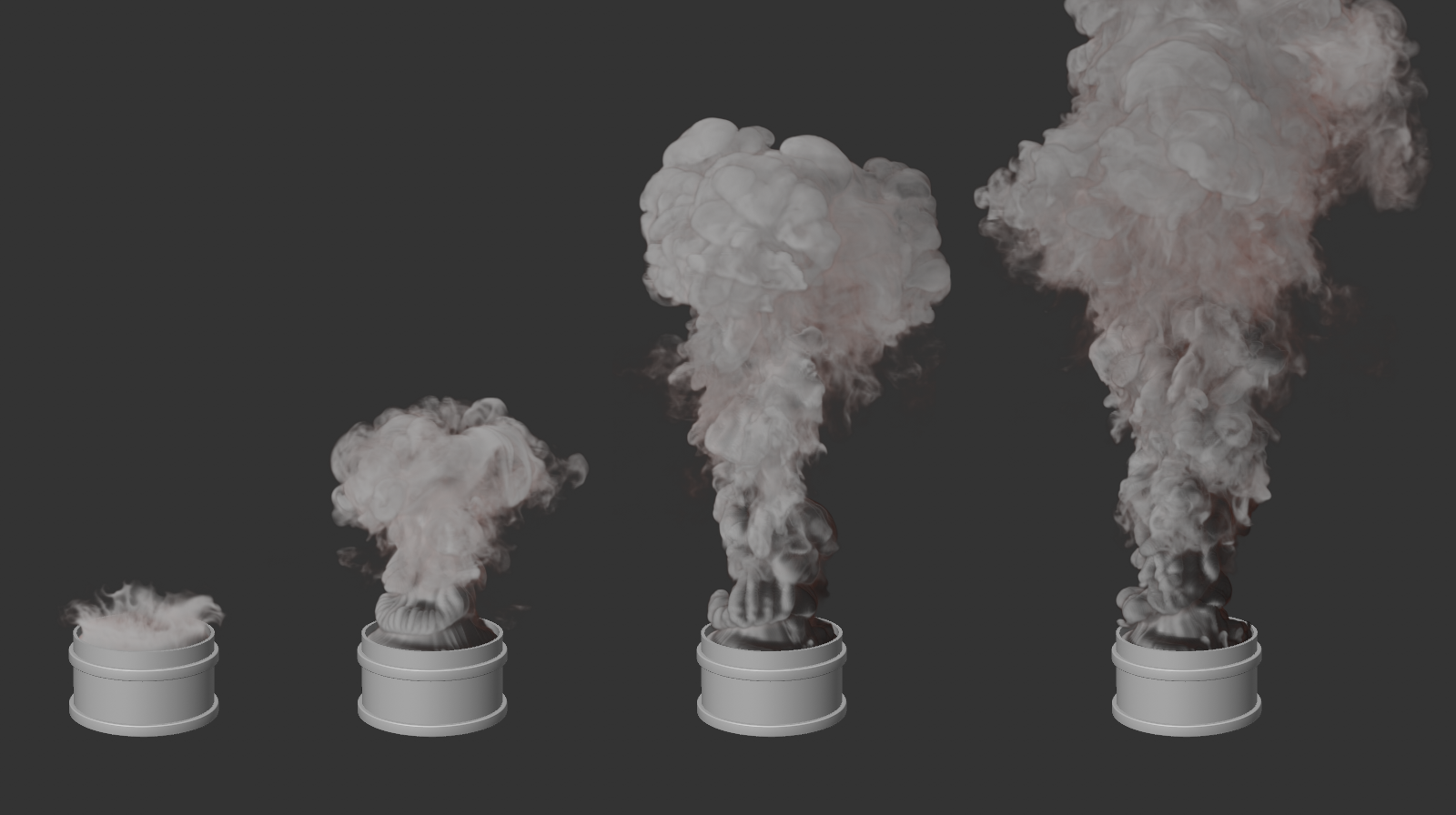 The simulation was calculated to be the same length for all four tubes shown here. From left to right, the Density Set values 1, 5, 10 and 15 were used here.
This can be used to add additional smoke or dust to the Emitter. The numerical value indicates the amount of density that is to be added per second at the emitter, i.e. added to any density already present in the area of the emitter. You will find a video example of this in the description of the Density Set value above.
Here, too, as with Set value, a low density is hardly visible because it moves slowly and automatically dissipates after a certain period of time. The effect can still be useful, for example, to keep the density in the simulated gas constant despite accelerated dissolution near the Emitter.
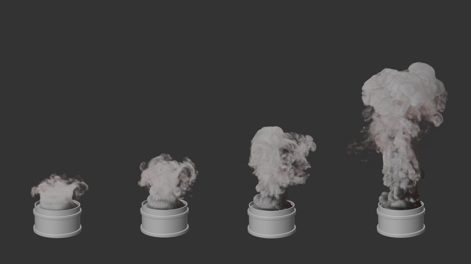 The simulation was calculated to be the same length for all four tubes shown here. From left to right, the Add Density values 10, 20, 40 and 100 were used.
Since this value can also be negative, it opens up additional possibilities for designing simulations that interact with each other. The following image shows an example of this. Gray smoke is produced by a bullet. In addition to the rising smoke column, a cube was created that uses a negative Add Density value and emits this "negative" smoke using the Velocity settings along the X-axis of the cube. In addition, this "negative" smoke was colored bluish.
Due to the negative density of the cube smoke itself remains invisible, but reduces the density of the rising smoke and also transfers its color to this "ball" of smoke. Due to the velocity of the cube smoke in X-direction, the gray smoke is also displaced laterally and at the same time dissolved by the negative density.
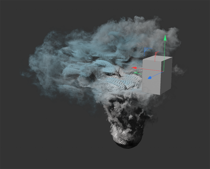 By assigning a negative density, new mixing effects and controlled resolutions of simulations can be achieved.
These color settings refer to the simulated density. By default, the density (to represent haze, clouds or smoke) is displayed in shades of gray. Enable this option to assign a custom color to the density to be displayed in the perspective view. Later, during the actual rendering, this color can be applied, or you can have the smoke colored again individually via a shader. If you simulate several Emitters for colored density, you can have their colors calculated opaquely or also mixed. This information can be cached and thus evaluated and rendered with the Redshift Volume or Pyro Volume shaders.
In addition, dissipation functions are also available for color values within the Pyro Scenesettings on the Pyro Output object. For example, a selected color can then be automatically faded to black over time. In addition, color information can also be taken over, e.g., from Thinking Particles or from the MoGraph Matrix object.
With this menu's settings, colors for the simulated density can be assigned and also the transparency of the density can be set via a Weight value. In addition, the calculation of the color mixture of different smoke colors can be affected. Use this option to enable or disable the use of colors and alpha values for density smoke. When switched off, full-covering, colorless smoke is produced. When using the Redshift Pyro Volume material, it can be recolored as desired.
This setting appears after expanding the Arrow icon in front of the Color Enabled option. A Vertex Color tag can be linked into this field, which can be used to store individual RGB colors and also Alpha values at the surface points, e.g., via Fields or direct painting with the Paint tool. Assigning a Vertex map also works, but there is no possibility to use arbitrary colors.
The Pyro Emitter can transfer the vertex colors to the newly generated density smoke. Note that the Alpha values also play a role in this. These can be used to control the visibility or opacity of the generated smoke. If the Color property of the simulation in a Redshift Pyro-v Volume material is used for the Color channels of the Scatter and the Absorption properties, the use of a separate Vertex map for Density can be omitted.
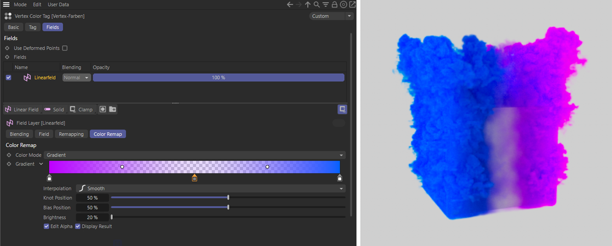 Here, a Vertex Color tag was assigned to a cube, to which the color gradient shown on the left, including alpha values, was assigned via a Linear Field. A Pyro Emitter tag was assigned to the cube and only the Density and Color options were enabled there. The Vertex Color tag has been assigned as a color map in the color settings. The result can be seen on the right.
Since the introduction of user properties for particles, these can also be used to control the emission properties. User properties can be created via the simulation settings for particles and configured with different data types and individually assigned names. You can find out more on this page.
Floating point or color A data is required to control the colors. If you assign a floating point user property, only grayscale can be assigned. When using the color data type, on the other hand, you have full control over the coloring and also the alpha component of the color values within the Pyro simulation. Simply enter the name of the user property to be used in the Color Map field.
The use of particle properties to control Pyro emissions is further simplified by the fact that you will find a small button behind the input field for the Color Map, which can be used to directly select the compatible particle properties currently available on the Particle Group.
Below you will find a simple example. Two user properties are used here. One, named neighbors, is filled in a Flock modifier and receives the number of immediate neighbor particles. A Data Mapper then evaluates this neighbor count and uses it to determine a new red component for the second color user property, which is called user color here. This user color is then evaluated by the color map on the Pyro emitter.
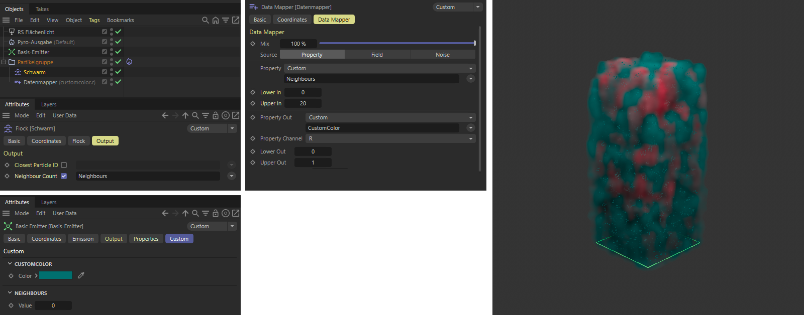 The particle density is evaluated here. The more particles move close together, the redder the color of the Pyro emission.
These colors can be stored as color cache at the Pyro Output object and can also be rendered normally via a Redshift Volume or Redshift Pyro Volume Material, as can already be seen on the right in the view above.
Here you can set an individual color for the editor display of the steam and smoke clouds. This color can also be stored at the Pyro Output object as a color cache and retrieved via a Redshift Volume or Pyro Volume Material.
The density simulation is mainly intended for the representation of smoke, fumes, mist or haze. If the Color Enabled option is active, any color can be assigned, e.g., to display white steam, smoke of any color or heavy soot clouds. However, defining the color does not change the visible opacity of the density. Especially for fog, cigarette smoke or haze it would be nice if you could control the visibility separately here, so that these elements appear somewhat transparent, for example.
A reduction of the generated density, e.g., via its Set value, would optically also have this effect, but this would then also change the entire simulation. After all, less density also means, among other things, less buoyancy and less turbulence within a smoke column or cloud.
The solution to this problem lies in the reduction of this Weight value. With lower values, the visibility of the density simulation automatically decreases when using the Color property within the Redshift Volume or Redshift Pyro material. The following pictures give an example of this. Please note that the display of transparency of the density in the Viewport is not representative. There, the selected color is simply displayed darker where there is reduced visibility.
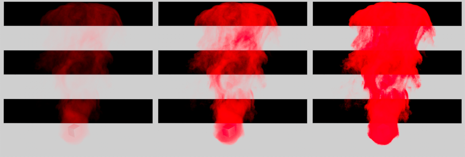 Here you can see a small cube that only emits density. In the background of the rendered views there are three dark polygon stripes to better examine the opacity of the resulting clouds. From left to right, the Weighting values 1%, 5% and 20% were used for the simulation. The expected opacity also depends on the actual density in the simulation.
The image above clearly shows how the simulation itself does not change its shape, only its opacity is affected. The following figure shows how the color information of the simulation was used for this purpose in the Redshift Volume or Redshift Pyro Material.
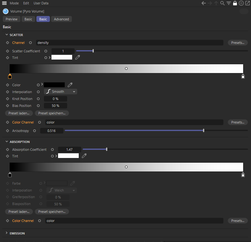 The figure shows the Redshift Volume Material and how the color property of the simulation was used there to control density visibility and coloration.
If active, this option ensures that the colors of the density do not mix with each other. So if you have different colored clouds simulated within the same Simulation Scene and they interpenetrate, no mixed colors will be calculated. The density color that is dominant in the respective area will always be displayed. This dominance is determined by the order of objects in the Object Manager. The further down an object, including its Pyro Emitter tag lies in the Object Manager, the more dominant its density color. The following image shows an example of this.
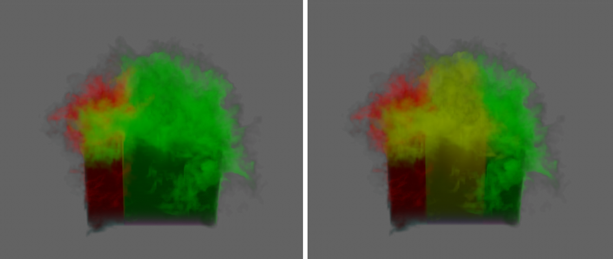 Here, two separate, laterally overlapping cubes were fitted with Pyro Emitter tags. The left cube produces only red smoke, the right one only green smoke. The left image shows the result with the Overwrite option enabled. To the right, this option has been disabled for both Pyro Emitter tags. The smoke colors will be mixed. The red and green smoke mix to create yellow smoke.
As can be seen on the left side of the image above, the green smoke dominates the result even though both cube Emitters are the same size and produce an identical amount of density. This is due to the order of the object entries in the Object Manager. The cube simulating the green smoke is below the cube with the red smoke in the hierarchy. Make sure the order of the Emitter objects in the Object Manager is correct so that the desired color appears in the foreground of the simulation.
If the Overwrite options of the two cubes are disabled, all simulated colors are equal and can mix with each other. This can be seen on the right side of the image above. Mixed colors will automatically be created between the smoke columns. The intensity of the mixing can be controlled via the Weight value and also animated. Also, the state of the Overwrite option can be animated, The resulting colors are preserved regardless of the state of the Overwrite option and the Weight value. Both settings are only relevant for the new density created at the Emitter. An example of this can be seen in the following image.
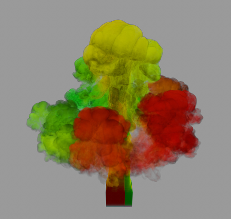 Here, the state of the overwrite option for the Pyro Emitter tags of both cubes has been animated, allowing additional variation in smoke coloration.
In this section you can have hot gas generated by the Emitter. The hot gas behaves similarly to the steam or smoke, but moves faster due to the defaults of the Pyro Scene settings from the Pyro Output object. Furthermore, the rising heat can also entrain and swirl the simulated air above the Emitter, which is thereby also transferred to the movement of the density.
You need these settings for the simulation of fire and flames. The hot gases can also be used to ignite simulated fuel. This can then abruptly generate additional density, temperature and pressure, which can lead to a strong change in the dynamics within the simulated gas cloud.
 Simulating a candle flame. Here, a small sphere at the location of the wick was used as an Emitter and was hidden for rendering.
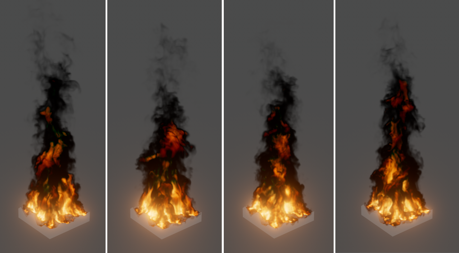 Simulating a burning floor. Here, the surface of the floor was assigned 100% values via a vertex map to allow only the upper part of the object to burn.
Activate this option to generate hot gases using the Emitter.
This setting becomes visible after clicking the Arrow icon in front of the Temperature Enabled option. By default, the hot gases are generated in the entire area of the object to which it's assigned. However, by using a Vertex Map, non-uniform generation of hot gas at the Emitter can also be realized. The selected temperature will then be emitted only in the areas that have Vertex Map values of 100%. Lower values reduce the temperature in these areas accordingly. With a Vertex Map value of 0%, no more hot gas is generated at all at the corresponding location of the Emitter. As with the Density map, by combining Fields with a Vertex map, it is possible to randomly vary the values of a Vertex map, for example, and thus achieve an even more natural fluctuation of the radiated temperatures at the Emitter.
As an alternative to a Vertex map, you can also use a Vertex Color tag. In this case, the Alpha values that were previously created using the Paint tool or Fields are evaluated and multiplied by the color brightnesses from the vertex colors.
Since the introduction of user properties for particles, these can also be used to control the emission properties. User properties can be created via the simulation settings for particles and configured with different data types and individually assigned names. You can find out more on this page.
To control the temperature, data of the floating point type and therefore specific values, e.g., between 0 and 1, are required. These are then multiplied by the temperature specified here in the Pyro Emitter tag. Simply enter the name of the user property to be used in the Temperature Map field. Only the particles where the specified user property is above 0 will then be able to generate temperatures.
You will find a simple example of the basic use in the description of the emissions map above.
The use of particle properties to control Pyro emissions is further simplified by the fact that you will find a small button behind the input field for the Temperature Map, which can be used to directly select the compatible particle properties currently available on the Particle roup.
Temperature Set[0.00..50000.00]
Enter the minimum temperature that should be present at the emitter here. If, for example, a higher temperature is generated by other Pyro Emitters in the same area, this temperature is transferred to the gas instead. The separate temperature Add value has a slightly different effect, as it adds to the existing temperature in the emitter area. If different emitters with an active Temperature Add property overlap, the gas in this area is said to overlap to a greater extent than when using Temperature Set, which means that only the highest temperature value at the emitter is transferred to the gas.
As with the Density property, settings on the Pyro Scene (see Pyro Output Object) can ensure that the gas temperature is automatically reduced and cooled down again over time.
This temperature is added per second at the emitter, i.e. it is added to an existing temperature in the area of the emitter. This also distinguishes the effect from the Temperature Set value, which instead defines the static minimum temperature at the emitter. The different effect compared to Temperature Set can be seen in the video above.
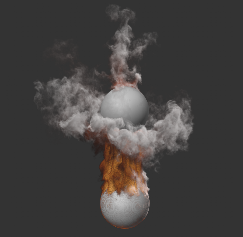
As Temperature Add can also be added negatively, interesting interactions between several Pyro Emitters within the same Pyro Scene are also conceivable. For example, one object may emit negative density and negative temperature, thereby dissipating and mitigating the rising heat and density of another Emitter. The following image shows an example. The upper sphere generates negative properties, which are applied to the lower sphere by means of a downward directed Velocity. The lower sphere generates positive density and temperature, which is cushioned and cooled when the two gas flows meet.
With these settings, additional fuel can be delivered at the Emitter. For example, think of this as a spray of fuel, similar to how gasoline is sprayed into the combustion chamber of an engine. This fuel has a certain energy density that is released as soon as the fuel ignites. At that moment, the temperature at the spot increases abruptly and the gas area expands. In addition, combustion also produces density (soot, dust, steam). Therefore, you can also already increase the density in the simulation by generating and igniting fuel. However, it is important to remember that combustion requires heat to get going. You define how hot it should be for the fuel to ignite in the Pyro Scene settings of the Pyro output object( Ignition Temperature parameter). This setting refers to the simulated ambient temperature of 0°C. A low ignition temperature can therefore already ignite fuel without simulated temperature.
In the Pyro Scene settings you will also find the parameters that can be used to control the conversion of fuel to density, pressure and temperature. Since the fuel can also be released abruptly, it is very suitable for creating explosions. In such cases, instead of using the Pyro Emitter tag, you can also work directly with the Pyro Fuel tag, which has already activated the creation of fuel at the Emitter and instead does without the simulation of density and temperature at the Emitter.
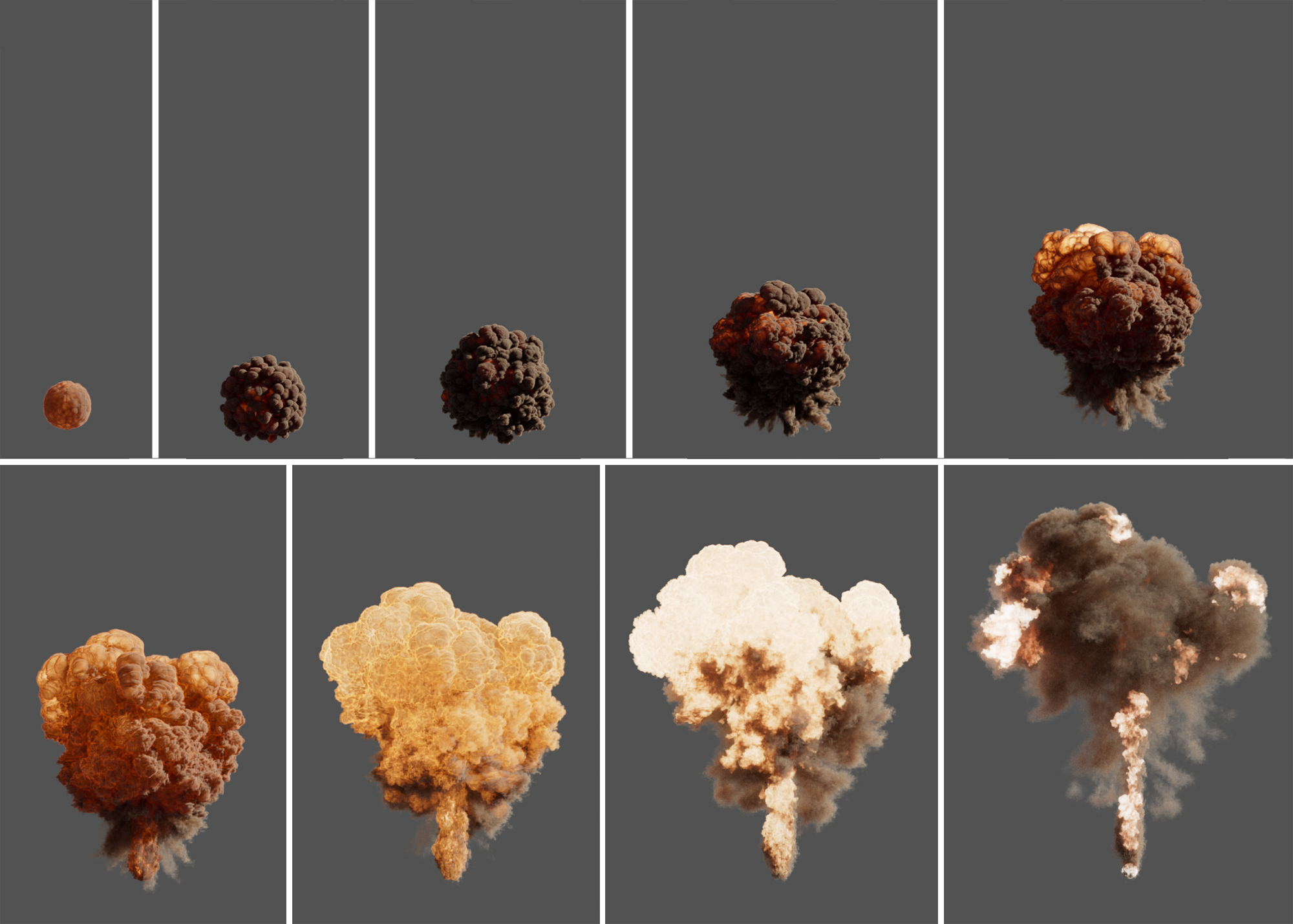 Here, only a very low temperature and a contingent of fuel was generated. When the fuel ignites, it expands, creating density and higher temperatures. As can be seen in the image sequence, explosions can be simulated using this method. The properties of the fuel are defined exclusively via the Pyro Scene settings of the corresponding Pyro Output object. On the Pyro Emitter tag, you only control the amount of fuel and how it should be generated over time.
Enable this option to generate fuel at the Emitter.
This setting becomes visible after clicking the Arrow icon in front of the Fuel Enabled option. Here you can optionally assign a Vertex Map of the object to make fuel generation non-uniform. Only where Vertex Map values of 100% are present, the set amount of fuel is produced. At lower Vertex Map values, correspondingly less fuel is ejected at the Emitter. No fuel at all is created at areas at which the Vertex map is set to 0%. Since a Vertex Map can also be animated and randomly varied by fields, for example, the amount and distribution of generated fuel can also be changed naturally during the simulation.
As an alternative to a Vertex map, you can also use a Vertex Color tag. In this case, the alpha values that were previously created using the Paint tool or Fields are evaluated and multiplied by the color brightnesses from the vertex colors.
Since the introduction of user properties for particles, these can also be used to control the fuel density. User properties can be created via the simulation settings for particles and configured with different data types and individually assigned names. You can find out more on this page.
To control the fuel density, floating point data is required, e.g., values between 0 and 1, which are multiplied by the fuel quantity defined via Set fuel and Add fuel. Values above 1 therefore increase the fuel quantity originally defined for Set fuel and Add fuel accordingly. Simply enter the name of the user property to be used in the Fuel Map field. Only particles with a user property whose value is above 0 will generate fuel.
The use of particle properties to control Pyro emissions is further simplified by the fact that you will find a small button behind the input field for the Fuel Map, which can be used to directly select the compatible particle properties currently available on the Particle Group.
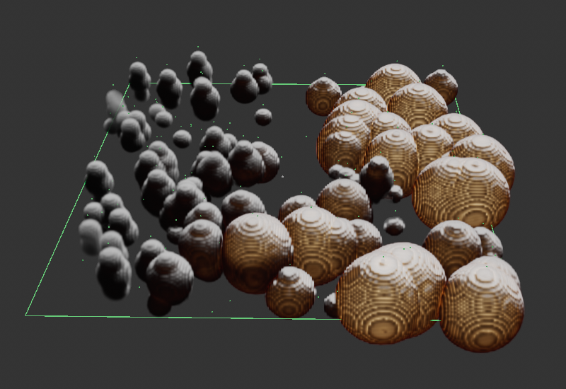 The particles emitted on the left were given a custom property value of 0, which increases to 1 for the particles to the right. Used for the fuel map, this results in stronger Pyro explosions on the right side of the emitter.
For example, fuel may be generated continuously or only within a specified time period. Various modes are available:
- Continuous: The amount of fuel defined with the following values is generated at the Emitter throughout the simulation. This can be used, for example, to represent a campfire or even a flamethrower.
- Frame Range: The fuel is output in the selected amount per animation image within an individual time period. This can be used, for example, to simulate an explosion that is to take place at a clearly defined time and for a clearly defined duration.
- Contingent: Here fuel is generated in the volume of the Emitter object but not ejected directly. Therefore, the actual amount of available fuel also depends on the size of the object. The conversion of this fuel into temperature, density and pressure is determined by the Burning Rate. This mode is only suitable for Emitter objects whose volume remains constant or, for example, for simulated substances whose Emitter volume is defined via Surface Thickness.
This setting is available for Continuous and Frame Range Fuel Type modes and defines the amount of fuel generated at the Emitter. As already explained in Density Set and Temperature Set, this is a minimum quantity of fuel that is added to the gas. If there are other emitters active in this area that may emit more fuel, their fuel quantity is used in the simulation instead.
The following setting Fuel Add, on the other hand, includes the amount of fuel already present in the emitter area and adds the desired value to it. Read here in the description of the Density settings or here in the description of the Temperature settings how this difference can have a practical effect on the simulation.
Similar to the properties of Density and Temperature, fuel can also be added over a period of time. Whereas with Set Fuel an amount of fuel is immediately created at the Emitter, with Fuel Add the selected amount of fuel is added to the simulation per second. In contrast to Fuel Set, the quantity defined with Fuel Add is added to the fuel already present in the emitter area. This is particularly relevant if several emitter shapes are used that overlap, for example.
Since negative values can also be used here, fuel that has not yet been burned can also be removed from the simulation again, as can be seen in the following figure.
 In this example, density, temperature, and fuel are emitted from a disc. The fuel ignites immediately after emission and is thus converted into additional density, temperature and pressure. The result can be seen on the left in the figure. After placing a deformed sphere in the center of the disc (shown in blue in the middle of the figure), which introduces negative Fuel Add values into the simulation, the result is shown on the right. The explosion now develops in more of a donut shape.
This is a special mode for the Fuel Type Frame Range, with which smaller explosions can be simulated very easily. Instead of generating fuel, which then has to be converted into temperature, density and pressure by combustion, pressure is output directly at the Emitter. This can be used very well, e.g., in conjunction with emitted density, to generate an explosion cloud, since the generated pressure acts from the Emitter in all directions. For this mode, density and temperature must already be present at the Emitter so that an explosion cloud can be created!
Emission Frame Start[0..2147483647]
Emission Frame End[0..2147483647]
These settings are only available with the Frame Range Fuel Type and define the start point and duration of the fuel output at the Emitter. Provided that the fuel is ignited directly at the time of Emission Frame Start, an explosion is immediately created at this animation image, which is evenly supplied with fuel until Stop Image Emission is reached and can grow during this period.
For the Continuous Fuel Type, this can be used to define the amount of fuel to be produced at the Emitter within one second. This amount of fuel therefore builds up slowly over the period of a second and is not available immediately.
A Fuel Burn Rate can be define in the Pyro Scene settings of a Pyro Output object. This defines how quickly fuel is converted to heat (temperature), pressure and density. If Matching Burn Rate is active, the amount of fuel is automatically calculated for the Continuous Fuel Type setting so that exactly as much new fuel is always generated as can be burned at any given time. The Set and Add values lose their effect as a result.
For the Contingent Fuel Type, this is the amount of fuel that will be released at the Emitter per frame of the simulation, if allowed by the Fuel Burn Rate of the Pyro Output object's Pyro Scene settings and the amount of fuel available (starting contingent multiplied by the volume of the Emitter object).
Initial Contingent[0.00..1000.00]
Think of this as a fuel tank whose volume is based on the object to which the Pyro Emitter tag has been assigned. The greater the value, the more fuel that can be stored in it and thus burned over a longer period of time.
During the simulation, the air in the vicinity of the Pyro Emitter can be seen. Due to the simulated temperature and pressure differences, as well as the superposition with random turbulence, turbulence occurs in the air, which is transferred to the density, for example. In addition, the density and, above all, the gas heated by the temperature, automatically both rise. Accordingly, typical smoke columns or flames blazing upward automatically at the Emitter. The forces acting within the simulation can also still be adjusted via the Pyro Scene settings on the Pyro Output object. For example, it is also no problem to let the smoke column of the density simulation fall to the ground with a positive Density Lift. The effect then resembles that of dry ice fog used in stage shows. The direction of movement of the simulated air can also be affected by Force objects, such as the Wind object. However, the Pyro Emitter tag itself also offers the possibility to influence the direction of movement and speed of the gas simulation with the following parameters.
 Here a Disk object produces fog (very low Density value for emission). A large plane with a Collision tag was placed below the disk, preventing the fog from falling further. A velocity of the type 'Add to velocity' acting along the X-axis moves the air and thus also the fog across the plane. To prevent the fog from rising too much in the process, the value for Density Buoyancy was set slightly above 0 in the Pyro Scene settings of the Pyro Output object. In addition, the Relative Density Dissipation and Absolute Density Dissipation were reduced to 0 to prevent the fog from dissipating.
Activate this option to affect the direction of motion or the amount of velocity within the simulation. The velocity is first transferred to the simulated air, which is in turn also transferred to the simulated gases.
The following options for mixing in a speed or direction of movement are available. The reference system for the direction of movement can be configured via the separate Coordinate System setting:
- Add to Velocity: The Direction is multiplied by the Strength and produces a velocity vector. This is added to the velocity of the gas during the simulation. A rising column of smoke will be continuously pushed away in the desired direction, as if by wind, for example.
- Set Absolute Velocity: Multiplication of Strength and Direction produces a velocity vector. All new Pyro properties created at the Emitter are assigned this velocity vector. However, in the subsequent simulation time, this velocity may change again due to density changes and other forces in the simulation. This setting can, for example, be used to define the starting direction and initial velocity of a gas.
- Change Direction: Here, the velocity within the simulated air is maintained and only its direction of movement is changed. By setting Direction to 1, 0, 0 in combination with the Global Coordinate System, the simulated air at the Emitter is then moved in the direction of the positive X-axis, which is transferred to the movement of the density, for example. In the course of the simulation, this direction of motion will then also be able to change again due to other effects, such as air turbulence, within the simulation.
- Set to Movement: This lets you define the amount of velocity on gases just formed on the Emitter. The direction of motion of the newly emitted gas remains unchanged. This works predictably only on non-animated Emitters.
This is the amount of velocity you want to define. A physical velocity always consists of a direction and an amount of the velocity. The complete velocity vector is therefore only obtained by multiplying this strength with the Direction Vector. The evaluation of the strength also depends on the Type setting.
This is the direction of the velocity. The size of the values does not matter. Your input will be standardized. The direction actually evaluated is therefore always only one unit long. You define the reference system for this Direction Vector via the separate Coordinate System setting. For example, with the Coordinate System setting Global, the specification 0,1,0 can then stand for the Y-axis always pointing vertically upwards or with Coordinate System Object it can also stand for the direction of the Y-axis at the Emitter object.
With these settings you can select the reference system for the Direction Indication. You can select from the following options:
- Local: The Direction vector refers to the axis system of the Emitter object.
- Global: The Direction vector is evaluated in the world coordinate system.
- Normal: This mode is only available if you are using the Dynamic geometry Emission type. The velocity acts relative to the respective Normal direction of the Emitter object.
 The object used for emission can be seen on the left. To the right are simulations with the coordinate systems Local, Global and Normal, each with the direction 0, 1, 0. Dynamic geometry has been activated as the Emission Type.
The divergence describes the strength with which the simulation diverges and spreads out. Positive values lead to faster propagation and an increase in the simulated volume, negative values contract the simulation. The following examples illustrate this effect.
These parameters can be used to influence the distribution of the newly-generated gas at the Emitter via an animated random pattern. This can also determine the appearance of the subsequent simulation. For example, larger Noise Scale values may also result in larger regions within the Emitter where density, fuel generation, or temperature may be greatly reduced (dark sections in the selected noise pattern). Accordingly, the behavior of the simulation also changes outside the Emitter. Therefore, always adjust these parameters individually to the size of your Emitter object and to the desired effect in the simulation.
In general, many of these settings should already be familiar to you, e.g., from the Noise shader. The principle here is the same, except that here the brightnesses of the noise structure is not represented pictorially, but control the activity within the Emitter object.
 All three images here show the same disk being used as the Emitter. All settings are identical and the simulation also shows the same time in each case. The only difference is in the Noise settings, which are used here to vary the distribution of the newly generated density on the disc.
Allows you to generally enable or disable the use of a noise structure for the intensities of the Emitter. In the off state, all object Voxels of the Emitter object will produce density, temperature or fuel uniformly.
The Seed value forms the basis for the calculation of the selected noise pattern. Therefore, a change in this value leads to a recalculation of the pattern and thus to a redistribution of the light and dark areas.
Here you can choose between the different noise patterns. A pictorial representation of the patterns offered can be found here at the description of the Noise shader.
The selectable noise patterns are three-dimensional structures that can be used here to vary the emission. Here you can select, for example, whether the noise should be calculated relative to the object axis system of the Emitter object or relative to the local world system.
If you opt for Global, the noise distribution would change in the volume, for example, when the Emitter object moves in the room. If Local is selected, the noise pattern would move with the animated Emitter object.
When using the Dynamic Geometry Emission Type, the UV coordinates of the emitting object can also be used to utilize the noise. This ensures that the noise structure deforms realistically even with deforming surfaces.
This defines the amount of detail in the noise structure. Larger values create correspondingly more variations in the pattern. Small values lead to a loss of contrast and details, as well as to a softening of the structure.
This allows you to scale the structure independently along the X, Y and Z axes and also distort it to fit.
This value allows you to increase or decrease the noise structure proportionally, i.e., evenly along all three spatial axes. This is the simplest way to adjust the noise structure to the size of the Emitter object.
The selected structure may change over time. This value specifies the speed of the cycle. The larger this value is, the faster the pattern changes during the simulation.
Additional options for animating the noise pattern are provided by the Movement and Speed settings.
This setting refers to the frequency setting with which the pattern can be animated. It can be helpful that the structure of the pattern is repeated during the simulation, e.g., to enable the seamless repetition of the animation.
Almost all noise types (exception: Electric, Gas, Random, Wavy Turbulence) offer this parameter, which loops the noise after the defined time in seconds (noise frequency must be greater than 0). The noise state then repeats every entered second. A value of 0 turns this effect off. Note that in doing so, for internal reasons, the animation speed of the structure may be adjusted and thus change.
Without this option, there will be an automatic variation of the selected noise pattern for each property of the Emitter. The distributions for density, temperature, and fuel in the Emitter volume thus differ from each other, as if a new Seed value had been used for each of these effects.
If the option is activated, the same noise structure at the Emitter is used for all three simulated Pyro properties.
Think of this function as a wind that can be used to move the selected structure in any direction. With this vector you define the direction of the displacement. The subsequent Velocity parameter then defined the speed of the displacement. Remember that the Motion vector is evaluated in the selected noise space.
With this percentage value you define the speed of movement the noise structure. You define the direction of the noise shift in the Movement parameter.
With these settings you can crop the brightnesses of the noise structure. All brightnesses that are lower than defined in Clipping below are set to 0, or black. All brightnesses greater High Clip are set to 1, or white.
However, you can also use these settings to invert the brightnesses in the noise pattern if you set Low Clip to 100% and High Clip to 0%.
Brightness regulates the general brightness value of the Noise. Values greater than zero will increase the brightness, values less than zero will decrease it.
Contrast adjusts the general contrast or range of values of the Noise. Positive values increase the contrast, negative values decrease it.

