Displacement
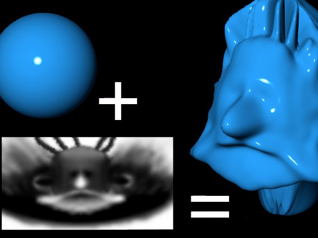
Displacement is similar to Bump, the difference being that here the object is actually (not just apparently) deformed. This difference is best seen at object edges. In the sphere example below, the left half of the sphere uses bump mapping, while the right half uses displacement mapping.
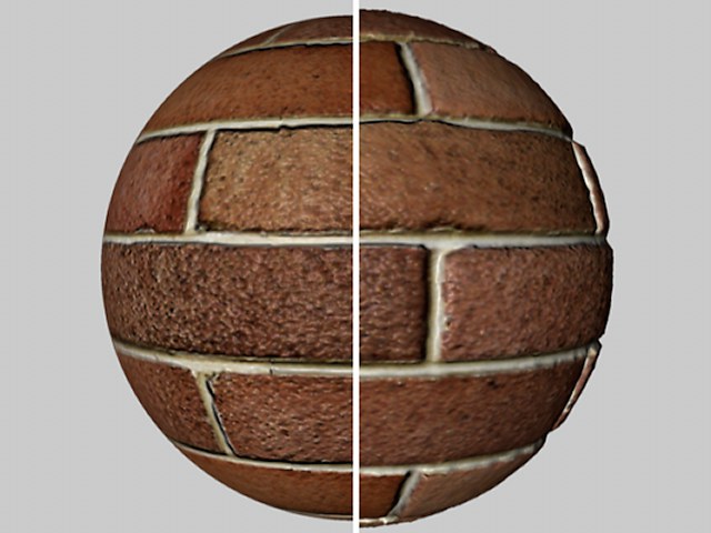
A bump map was used on the left half of the sphere and a displacement map on the right half. You can see that the edge of the sphere with the bump map applied is smooth and that the displacement edge is deformed. The slight deformation also leads to shadow effects within the object surface itself.
General Information
- Always disable the Perfect Sphere option when creating a sphere. Leaving this option enabled will prevent a displacement map from being calculated.
- If several displacement materials are assigned to a given object, the maximum values will always be used. Example: An object has 2 different displacement materials on 2 selections. The first displacement material has a subdivision level of 4 and the second 6. The entire object has a subdivision level of 6. Even though the entire object is subdivided, the displacement will only be applied to the defined selections.
- If problems should occur when using the RGB (X, Y, Z local) mode, such as no local displacement, enabling the Material tag’s Use UVW for Bump option can help.
-
Please also not the following functions:
- Sculpting
- Bake Material
which can be used to create displacement textures.
This slider allows you to adjust the maximum displacement defined by the Height setting (the Strength and Height values will be multiplied together to control the maximum displacement).
Defines the height of the displacement, which can be modified by Strength value.
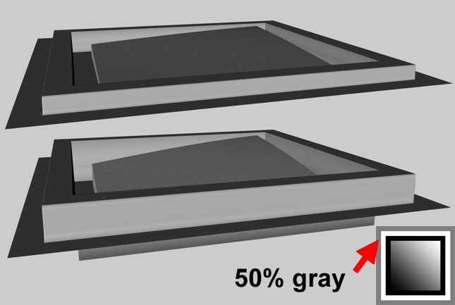 Intensity mode (top) and Intensity (Centered) mode (bottom).
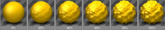
In the Intensity mode, the displacement takes place in the positive direction. Black parts in the displacement map produce no displacement, white parts produce maximum displacement.
 Intensity mode.
In the Intensity (Centered) mode, the displacement can take place in both positive and negative directions. A gray value of 50% results in no displacement. White produces maximum positive displacement, while black produces maximum negative displacement.
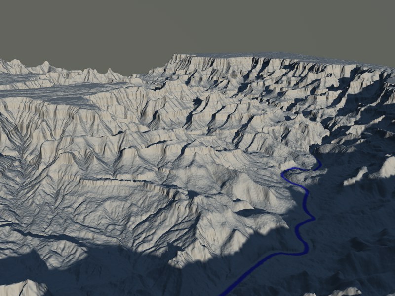
The displacement can take place in the negative or positive direction according to the red and green values in the texture. Green values raise the displacement, red values lower the displacement. A black color results in no displacement, it is purely the red and green components that control the displacement. A pure green (RGB: 0,255,0) and a pure red (RGB 255,0,0) lead to maximum displacement in the positive and negative directions respectively.
These modes control the displacement spatially according to the texture’s RGB components. The components define the following directions:
- Red: X
- Green: Y
- Blue: Z
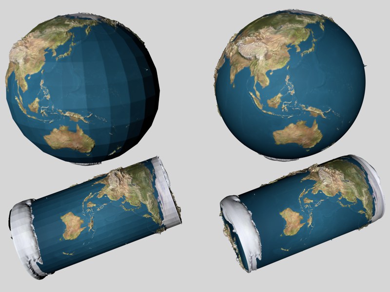
Depending on the mode selected, different coordinate systems will be used for deformation. The most flexible and recommended mode is RGB (XYZ Tangent) (of course as long as the displacement texture was also created in this mode!) because this allows object deformations (e.g., via Deformers) that won’t result in faulty deformations, as can be the case with other modes. This mode is indispensable specially in conjunction with character animation, is brought to life by moving joints.
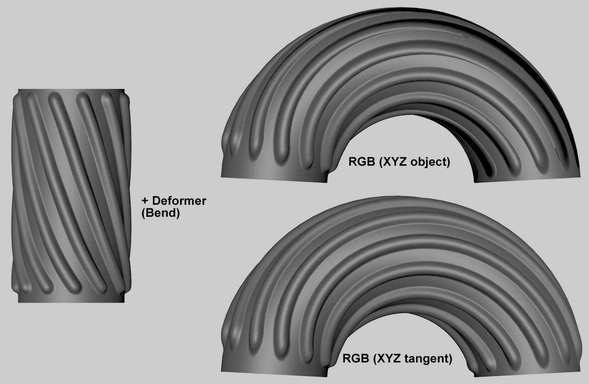
The cylinder in the image above as a displacement texture applied to it and was deformed using a Bend deformer. The displacement texture created using RGB (XYZ Object mode at the top right is faulty; the displacement texture at the bottom right is correct and was created using RGB (XYZ Tangent) mode.
Here an image texture or a 2D shader can be defined. Refer to the Textures chapter for details.
 Sub Polygon Displacement
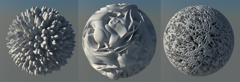 Images of all Noise types in conjunction with SPD can also be found here.
This activates SPD. If the option is disabled, normal displacement will be used (only existing object points will be affected). See Advanced Render / Sub-polygon Displacement.
 Balls of slime (two sphere primitives with their Render Perfect option disabled) with a subdivision of 2,4 and 8 (from bottom to top).
This is where you determine the SPD subdivision. This goes for the entire object to which the material has been applied. It can be well worth the trouble to delete the object’s hidden sides in order to reduce the number of surfaces that must be subdivided.
As is often the case, higher values produce better results but add to the render time.
Note that you may need to change this value for each object. If you set the same SPD value for a Cube primitive and a Plane primitive, for example, the results will be different because the standard Cube has six polygons and the standard Plane 400. The same applies to an object that contains various subdivisions such as a character that has many more polygons for her face than for her legs. If you use the same SPD values for these parts, the nose polygons will be just as strongly subdivided as the much bigger polygons for the legs.
For each existing polygon, the following polygon count will be calculated internally:
- Triangle: (2 to the power of Subdivision Level) * (2 to the power of Subdivision Level) / 2
- Quadrangle: (2 to the power of Subdivision Level) * (2 to the power of Subdivision Level)
A Subdivision Level of 8 would result in the following (internal) polygon count:
Cube: 6*256*256 = 393,216 polygons.
Plane: 400*256*256 = 26,214,400 polygons.
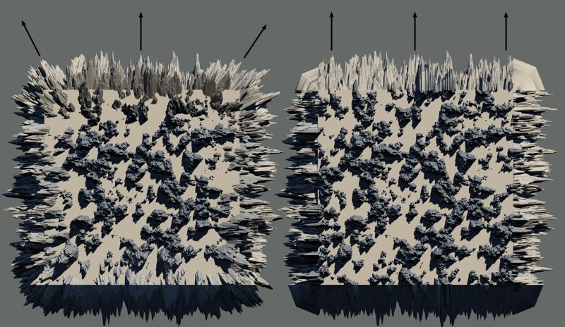
 Round Geometry disabled (left) and enabled (right).
Since SPD cannot calculate a normal Phong shading when it is applied, a special algorithm similar to that of the Subdivision Surface is used to ensure that the object is rounded before the SPD is rendered.
This is specially designed to smooth surfaces that appear facetted after SPD rendering. Contours (polygon edges that have no adjoining polygons) remain unaffected if Round Contours is disabled.
Since this can also cause unexpected results, as seen in the following example, you can also disable the option.
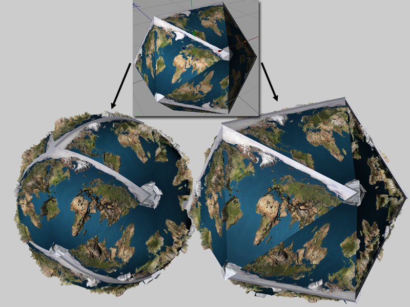 Round Geometry disabled (left) and enabled (right).
To apply the earth texture to this platonic body (icosahedron) without smoothing, simply disable the option.
Round Geometry and Subdivision Surface
As mentioned above, Round Geometry uses an algorithm similar to the one used by Subdivision Surface. In some cases, you can do without Subdivision Surface entirely and use SPD to smooth instead. If you use SPD and Subdivision Surface on the same object, keep in mind that the subdivisions will be multiplied because the SPD subdivision will be applied to the object after it has been subdivided by Subdivision Surface.
If this option is enabled, contours (polygons that have at least one adjoining polygon missing) will also be rounded. Disable the option for objects whose contours would be adversely affected by the smoothing, such as is pictured below where the Plane should retain its shape.
 Round Contours enabled (left) and disabled (right).
This option determines whether the rounded geometry should be used to define the texture coordinates. In most cases this will lead to more intuitive results. It can also lead to fewer artifacts.
Because the calculation can take up to 10% longer and in some cases the projection must be onto the non-rounded geometry, you have the option to disable this feature.
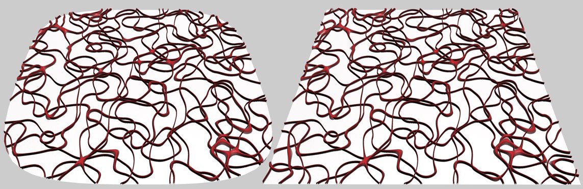
 The texture with SPD (bottom left). Map Rounded Geometry enabled (left) and disabled (right).
For this example, an SPD texture was applied to a Plane consisting of only one polygon with Round Geometry and Round Contours both enabled. The result on the left is what can normally be expected: the texture’s density has not been changed in the rounded areas. In contrast, the result pictured on the right shows that the texture was projected prior to rounding and was squashed during the rounding process.
Use this setting to define how the texture should be projected:
- Before applying the Sub-polygon Displacement (setting not active).
- After applying the Sub-polygon Displacement (setting active).
So what does this mean, exactly? Since applying the SPD will result in a new geometry being created, this would depend on when the subsequent texture projections should be applied (with the exception of displacement since this channel is a prerequisite for the effect itself). Different effects can result, depending on the shader, bitmap and method of projection used. In the example below, a texture was placed onto a layer as an initial step:
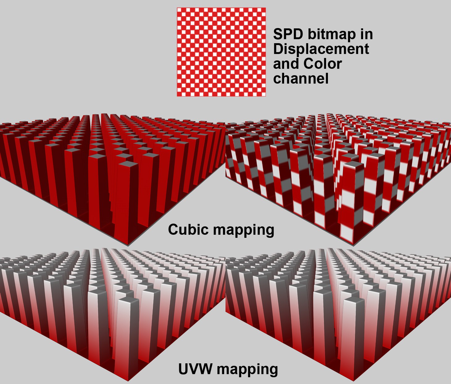 Various projection effects: Left Map Resulting Geometry not active, right Map Resulting Geometry active.
When mapping a cube you can clearly see how the colors are projected, depending on whether or not Map Resulting Geometry has been activated. In contrast, no difference can be seen when using UVW Mapping since SPDs do not change any UV coordinates.
3D-based shaders (e.g., noise, wood, rust, etc.) behave differently. Since they do not require UV coordinates, they can also be used to texture the edges of extreme displacements, as seen in the UVW mapping example below:
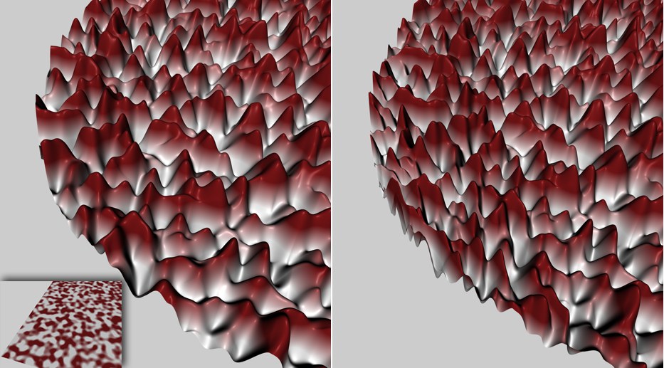
 A 3D noise shader was used. Left: Map Resulting Geometry not active; right Map Resulting Geometry active.
In general, activating this option is not recommended for animated objects that change their shape (normal position or rotation animations are o.k.) since it can cause textures to jump.
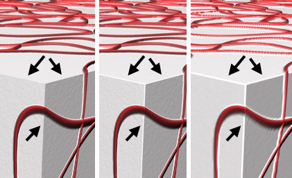 From left to right: Keep Original Edges enabled, disabled, still disabled but with a lower Subdivision Level.
If this option is enabled, hard Phong edges will remain hard. If the option is disabled, the edges will be rounded according to the subdivision Level.
The effects of this option mostly occur only when the Round Geometry option is disabled.
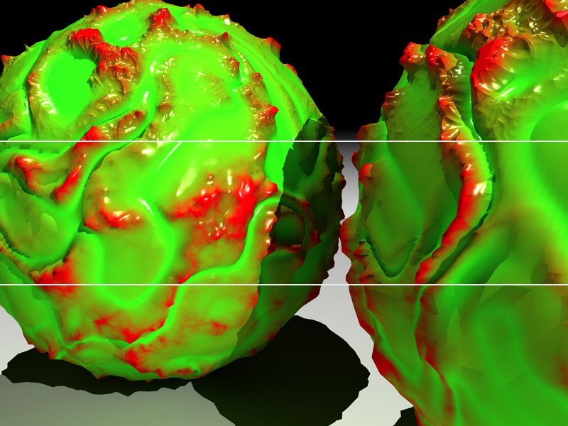
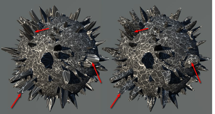
 Best Distribution enabled (left) and disabled (right).
As you can see in the example above, the enabled Best Distribution option changes the direction of the displacements towards the Phong edges. The closer a displacement is to the edge, the closer it is brought to this edge and the closer it follows the virtually rounded Phong normal.
What this is all good for: In most cases, this setting will ensure a soft, uninterrupted transition of the SPD over phong edges.
If Best Distribution is deactivated (only makes sense if one of the intensity modes is set in the Type setting) each displacement will point up perpendicularly. This can lead to inflated displacements at the edges. This is a result of displacements that overlap edges and basically stand at a right angle to each other will have the space between them filled. Activate this option if modeling cities that are viewed from a greater distance or, for example, castle stones.