Simple
Here you will find a series of parameters with which you can create fan-like, warped Spline constructs. Most of these parameters can be opened to display additional settings, including a function curve and a field in which you can enter a formula. These settings can be used to modify the Spline itself (Length, Angle H, Angle P, Angle B) or individual Spline segments (Curve, Bend, Twist, Width).
The function curves’ and formulas’ values will be multiplied by the corresponding "main" parameter.
This value defines the length of the MoSpline or its individual segments. Note that this value is not absolute. The following two parameters work in conjunction with this length.
Use this curve to modify the length of the MoSpline segments. The left end of the curve represents the first segment and the right end of the curve represents the last segment.
For those users with programming skills, the Formula field can be used to create advanced effects. The value resulting from this field will be multiplied by the parent parameter (e.g., the Curve). In addition to the usual Functions, the following can also be used:
t, time
The current animation time.
ind, index, i, number, n
The current segment point’s index number (for Curve, Bend, Twist, Width). Internally, each segment’s points are numbered consecutively.
seg, segment, s
The current segment’s index number (for Length, Angle H, Angle P, Angle B). Internally, the segments are numbered consecutively.
cnt, count, c, total, tot
The total number of segment spline points or of segments.
Example
Segment Number Formula
 The formula "1+sin((ind/cnt)*360)".
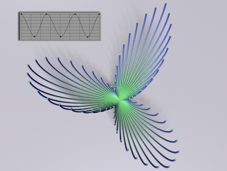
Let’s say you want to create a sinus-shaped dispersion of a MoSpline’s length values. Enter 1+sin((ind/cnt)*360) into the Formula field. What will the result be? An individual factor will be calculated internally for each Spline segment, which primarily results from "ind/cnt".
Let’s say your MoSpline has 40 segments. The first segment has an index number of "0" and the third has an index number of "2", and so on. "cnt" has a constant value of 40. Hence, the first segment will be 0/40=0, the third segment 2/40=0.05, and so on. The factor "360" ensures that a sinus wave is run through; the summand of "1" ensures that no negative values arise.
Formula Along an Individual Spline Segment
 The formula "sin((ind/cnt)*360)".
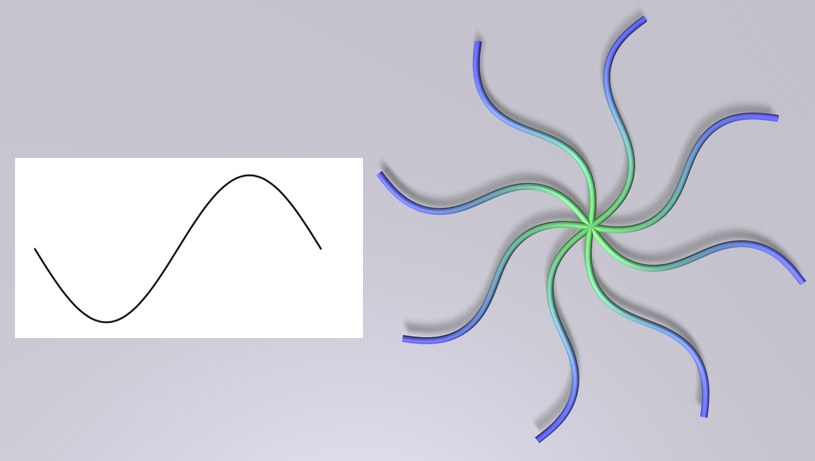
Enter the formula sin((ind/cnt)*360 into, for example, the Curve field. Similar to the previous example, this formula also results in a sinus curve being run through completely. This time, however, along each individual Spline segment. As you can see, each segment first curves in one direction, then curves in the opposite direction. This represents the positive and negative run through the sinus curve, respectively.
Use this setting to define the number of points per (unlengthened) Spline segment. Here, the same applies as to all spline subdivisions: a sufficient number is required in order to guarantee a constant and harmonious Spline shape. Too few points will result in an angular Spline.
 Left: few segments; right: many segments.
Use this setting to define the number of Spline segments. Make sure that either the Angle H, Angle P or Angle B value is not set to 0. Otherwise all Spline segments will lie on top of each other.
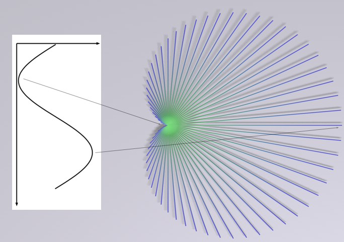
This angle is the angle between the segment at the MoSpline’s origin and the last segment of the Spline curve created (rotation around the Y axis). The Spline segments in-between are arranged uniformly (as long as the Spline and Formula settings don’t have settings to the contrary).

This Spline setting defines how the Spline segments between 0° and the Angle H value will be arranged. Details regarding working with Splines can be found here.
See Formula.
This angle is the angle around the last segment of the curve originating from the MoSpline’s origin (rotation around the X axis). The Spline segments in-between are arranged uniformly (as long as the Spline and Formula settings don’t have settings to the contrary).
This Spline defines how the Spline segments between 0° and the Angle P value will be arranged. See also Spline.
See Formula.
The Angle B lies between the first and last segment that originate from the MoSpline (rotation around the Z axis). The Spline segments in-between are arranged uniformly (as long as the Spline and Formula settings don’t have settings to the contrary).
This Spline curve defines how the Spline segments will be arranged between 0° and the Angle B value. See also Spline
See Formula.
If a single Spline segment should curve along its length (around the Y axis (based on the object origin)), enter a corresponding value here. This value defines the angle between the tangent of the first and last segment point. However, this value can be influenced by the Spline and Formula parameters. Enabling the Maintain Angle option will help offset this effect.
This Spline curve defines how the curve should behave along the length of the Spline segment.
See Formula.
These settings are used to define the value range through which the main parameters, as defined by Spline, Formula and related settings, will pass. The Maintain Angle option must be disabled.
If a value has been defined for one or more of the Curve, Bend or Twist parameters, these can be affected adversely by the Spline or Formula values. Enabling this option will help offset this effect.
The Spline deformation for the Curve, Bend and Twist parameters is normally done using the local coordinate system, which means the differences between angles is calculated from one segment to the next and each segment point has its own coordinate system.
Enable this option to calculate the angles using the world coordinate system. This image shows how this effect can look (used in conjunction with the Twist parameter).
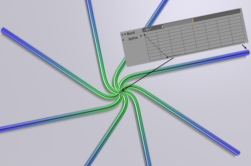
If a single Spline segment should bend along its length (around the Z axis (based on the object origin)), enter a corresponding value here. This value defines the angle between the tangent of the first and last segment point. However, this value can be influenced by the Spline and Formula parameters. Enabling the Maintain Angle option will help offset this effect.
This Spline curve defines how the bend should behave along the length of the Spline segment. See also Spline.
See Formula.
These settings are used to define the value range through which the main parameters, as defined by Spline, Formula and related settings, will pass. The Maintain Angle option must be disabled.
If a value has been defined for one or more of the Curve, Bend or Twist parameters, these can be affected adversely by the Spline or Formula values. Enabling this option will help offset this effect.
The Spline deformation for the Curve, Bend and Twist parameters is normally done using the local coordinate system, which means the differences between angles is calculated from one segment to the next and each segment point has its own coordinate system.
Enable this option to calculate the angles using the world coordinate system. This image shows how this effect can look (used in conjunction with the Twist parameter).
If a single Spline segment should twist along its length, (around its Z (axis based on the object origin)), enter a corresponding value here. A value of 180° will rotate the last segment 180° compared to the first segment. If all other bend and curve values are set to 0, this effect will first be apparent when the MoSpline is made a Child of a Sweep Object.
The Sweep Object contour will twist accordingly. However, this value can be influenced by the Spline and Formula parameters. Enabling the Maintain Angle option will help offset this effect.
This Spline curve defines how the twist should behave along the length of the Spline. See also Spline.
See Formula.
These settings are used to define the value range through which the main parameters, as defined by Spline, Formula and related settings, will pass. The Maintain Angle option must be disabled.
If a value has been defined for one or more of the Curve, Bend or Twist parameters, these can be affected adversely by the Spline or Formula values. Enabling this option will help offset this effect.
The Spline deformation for the Curve, Bend and Twist parameters is normally done using the local coordinate system, which means the differences between angles is calculated from one segment to the next and each segment point has its own coordinate system.
Enable this option to calculate the angles using the world coordinate system. This image shows how this effect can look (used in conjunction with the Twist parameter).
Most MoSplines end up being made a Child object of a Sweep Object. This parameter is used to define the width of the Sweep Object itself (instead of being defined by the size of the Spline).
This Spline curve is used to define the width along the length of the Spline segments. Details on how to use this Spline curve can be found here.
See Formula.