How to use the Attribute Manager
Editing
To edit a parameter in the Attribute Manager, do one of the following:
- Enter the new value into the parameter’s text box.
- Next to the parameter’s text box, you will find two arrowheads, one pointing up the other pointing down. Drag these arrows left or right to increment or decrement the value.
- Position the mouse pointer on the parameter’s text box and rotate the mouse wheel (if present and supported by your operating system) to increment or decrement the value.
-
Click in the numeric value field you want to modify and press the Up or Down arrow keys on your keyboard to change the value accordingly. The selected digit or the one to the right of the cursor will be changed.
Formulas can be entered into the numeric fields. Values can also be entered for multiple selections of objects. See Formulas for details.
See Creating Keys in the Attribute Manager for information about creating, editing and deleting keyframes in the Attribute Manager.
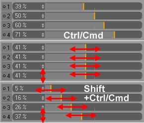 From top to bottom: Initial state; +Ctrl-key, all values will be applied to the selected parameter; +Ctrl + Shift-keys all parameters will be changed relatively
Parameters of the same type can simultaneously be set to the same value. Simply select all parameters (select the first and Shift+click on the last) and, while simultaneously pressing the Ctrl-key, either drag the slider or click one of the small arrows belonging to the respective value. You can also enter the new value manually and subsequently press Ctrl+RETURN.
This also works for the option fields (select the respective options and change them all simultaneously with Ctrl+click) and text fields (select several text fields, enter text into only one of them and subsequently Ctrl+RETURN).
If several values should be changed relatively at the same time, press Shift+Ctrl while changing the values.
Resetting parameters: As long as a change of values has not yet been confirmed (slider has not yet been released; the mouse button has not been released; the RETURN-key has not yet been pressed after entering a value) its initial state can be reset by pressing the Esc-key.
The Field lists offer special types of sliders that are more intuitive and faster to use compared to those for other features. The entire slider works as a single clickable interactive element.
They work as follows:
- Click on the slider and drag it left or right
- Click and release at a specific location along the slider
- Click and hold on the value and drag the mouse vertically
- Press Ctrl/Cmd in combination with the above methods to set multiple selections to the same value. If you also press the Shift key, all value differences will be maintained.
- Double-click on thevalue or blue handle to enter a numeric value and confirm by pressing the Enter key on your keyboard. The value can be increased or decreased using the up and down cursor keys.
Right-click on one of the arrows to set a parameter value back to its default value (the value upon creation of the element). Simultaneously pressing the Ctrl-key set multiple selections back to their default value.
If you want to set parameters such as selection menus, option value fields, colors, gradient
Navigating the Attribute Manager
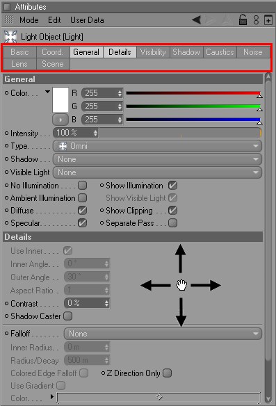
Near the top of the Attribute Manager you will find tabs for each parameter group of the selected elements. To display a group’s parameters, click on its tab. The parameters will appear below the tabs, where you can edit them.
To display multiple parameter groups, right-click (Windows) or Shift-click (macOS) each group’s tab. To remove a tab from the selection, right-click or Shift-click the tab again. Selected tabs are highlighted with a bright color.
There are further ways to navigate the Attribute Manager:
- Drag, say, a material from the Material Manager and drop it onto the parameter group tab for a Material tag. The tab will be activated if it is not already (this also works with Managers in the grouped tags).
- Click and hold down the mouse button and drag over the parameter groups that you want to display.
Scroll bars will appear if there is insufficient display space. To scroll the display space, drag the scroll bars or click in an empty part of the window and drag.
Drag from an empty part in the Attribute Manager to scroll the parameters.
History Buttons
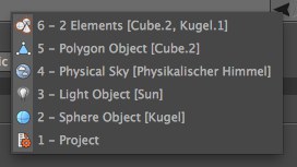
Right-clicking on the navigation arrow will open a menu with the previously displayed elements, which gives you much quicker access to these items.
You will find three history buttons above the parameter group tabs: a left arrow, right arrow and an up arrow. Cinema 4D keeps track of the history of elements already displayed in the Attribute Manager — use these buttons to navigate through them.
Click the left or right arrow button to move back or forward one element in the history respectively.
Click the up arrow button to move up by one hierarchical level. This also works with shaders. For example, suppose you have created a material and loaded the Fusion shader into its color channel. You have also loaded shaders into the Fusion shader itself, i.e., you have shaders within shaders. Using the up arrow button, you can display the settings that are on the next level up.
For tags, this button will adapt to the parameters of the corresponding object.
 Only those parameters containing the term "Clip" are displayed.
Ever get lost in the jungle of parameters in an over-filled Attribute Manager? Try clicking on the search icon on the top-right bar of the Attribute Manager. A specific term can be entered in the field that appears with which the results can be filtered. Only those parameters that contain this term or string will be included in the search results. All terms tucked away in the selection menus will also be included in the search.
The filter functions across all elements comprehensively, i.e., if a new element is displayed in the Attribute Manager it will also affect the results of the filtered search.
When you click on the Filter icon at the top right of the Attribute Manager, a small field with 5 settings will open. These are filters that filter settings based on a few criteria, e.g., to show only animated settings.
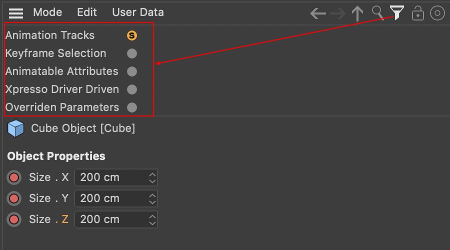 Here, only the cube’s animation Tracks are displayed.
Click on one of the following Filter icons - multiple filters can be enabled - to display the respective settings for the element selection (object, tags, XPresso Nodes, etc.):
- Animation Tracks: All settings that contain an animation Track - with or without keyframes
- Keyframe Selection: All settings for which Autokeying has been selected (see Add Key Selection.
- Animatable Attributes: All settings that can be animated, i.e., the ones whose circle is filled next to the respective setting
- XPresso Driver Driven: All settings that use XPresso to control or be controlled (see XPressions).
- Overridden Parameters: All settings that the Take System allows to be overwritten
(see Overwrite).
Settings that are made up of sub-channels (e.g., colors, vectors) will each be displayed with all of their components if at least one of the sub-channels is included in the filter search.
Just because an element’s parameters are displayed in the Attribute Manager it does not necessarily mean that object is currently selected. This can occur, for example, if the Attribute Manager is locked. Double-clicking an element’s icon at the top left of the Attribute Manager will automatically select that element in the corresponding Manager window. The following elements can be selected using this method:
- Objects
- Tags
- Materials
from the menu that appears.
Sets all values currently displayed in the Attribute Manager tab back to their default values for the selected objects, i.e., the values that are defined when an object has been newly created.
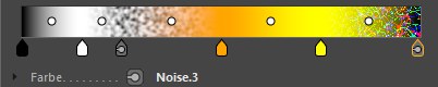
 Access the Noise settings via the Material tag’s parameters.
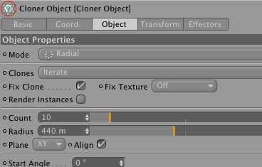
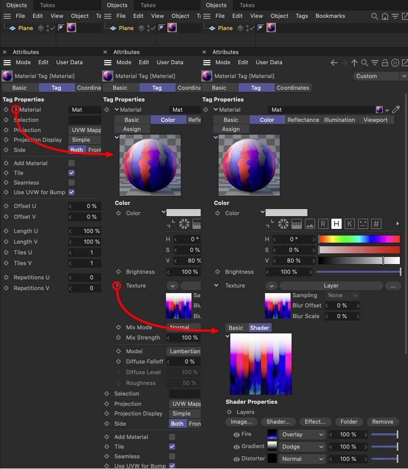
Right-clicking on the black arrow next to linked parameters will display the linked element’s properties (double-clicking the linked field will display that parameter exclusively), which can also be modified here. This very practical functionality saves you from having to search through various manager windows in order to find the desired parameter.
 Two options are available for initiating the selection process.
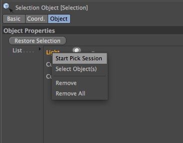
Lists (e.g., Selection object or Light object (Include/Exclude)) offer the following context menu:
All elements that contain lists (e.g., Selection object or Light object (Include/Exclude)) have a context-sensitive menu (select and right-click on an item in the list):
- Select Object(s): Selects currently selected objects in the Object Manager
- Select Tag(s): Selects currently selected tags in the Object Manager
- Remove: Removes currently selected elements from the list
- Remove All: Removes all elements from the list
For every link field, a selection process can be initiated by clicking on the circular arrow button at the right of the field (or by selecting the Start Pick Session option from the dialog menu). All you then have to do is select the corresponding element (e.g., object, material, tag, layer, etc.) in the Viewport or Manager. When selected, the element will automatically be placed into the link field.
To start the selection process, click on the arrow button. One of the following steps will end selection process:
- Clicking on an appropriate object in the Viewport or Object Manager
- Pressing any key on your keyboard
- Pressing on the arrow button again
- Clicking on any empty region.
You can also double-click on an object in the list to display its properties in the Attribute Manager.
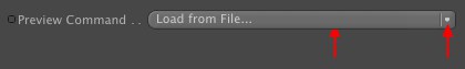
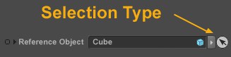
This interface element is a combination of selection menu and command button. Click on the left part to execute the command, which in turn can be selected by clicking on the right end of the button.
Path lists
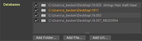
In the Preferences menu, for example, you will find Path lists in the Asset Browser menu to which Cinema 4D will search for asset databases. These interface elements work as follows: Click on the Add Folder button to select a path that will be added to the list. Select a path to delete it from the list (paths can be selected individually or multiple paths can be selected using the Cmd/Ctrl or Shift keys.
Each path has the following options:
- Enable/disable: This will enable or disable the databases. If changes are made to the databases, these can then be reloaded.
- Path folder: Click on a path to open the path dialog to change the current path
- Path: Double-click on the path to enter a path manually
- Save Project incl. Assets: Using this option you can determine if assets from the database should be exported using the command of the same name.
Use and context menu
If you right-click on the parameter name, the options Path List, String, Multi-Line String and Static Text will be made available, which allow different views of the Path list. Especially interesting is the Multi-Line String option because the elements can be selected, copied and added to other Path lists. If a path cannot be found or if it contains invalid characters it will be colored red.
Here you will find the following commands as buttons or in the context menu:
Add Folder
Selecting this command has the same function as clicking on the button of the same name below the list. A dialog window will open from which you can select a path. Alternatively you can simply double-click on an empty region of the list field.
The lists can also be filled with other entries from other locations.
Add URL
See previous command, only that here an internet address (URL) can be defined for a directory or file.
Change Folder
A dialog window will be opened from which you can select a different path.
Delete
This deletes the selected path.
Delete All
This will delete all paths from the list.
Show in Finder
This opens the selected path in the Explorer/Finder.
Add File
Not included in all Path lists, this command add a file. This can, for example, be a .zip file that contains a zipped asset database.
Function Graphs
Here you will learn how to use Cinema 4D’s function graphs. A function graph defines how a value or parameter falls off over a certain distance.
There are many places in Cinema 4D where you can define a custom function graph. For example, you can define a function graph for the Bevel tool, Sweep object and Spline Deformer object.
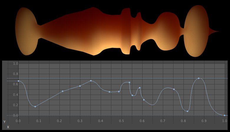
In the image above, for example, the Scale setting for a Sweep object was defined via a Spline curve. For a Sweep object, the Y coordinate represents the scale (i.e. the assigned parameter) and the X coordinate the Spline length (for other objects known as the distance from the origin).
Ctrl+Click on the graph to create each point.
Editing the Function Graphs has been adapted to the Timeline’s F-Curves.
You can select multiple Spline points by
- dragging a selection box (the buttons described in the following point work here as well)
- clicking on Spline points. Simultaneously press the Shift or Ctrl/Cmd keys to add or deselect points, respectively.
Selected Spline points can be deleted by pressing the Del.
Each Spline point (can be defined via the Interpolation option) has a tangent that defines the curve in proximity to the point. The tangent can be adjusted by clicking on and dragging the handles at each of its ends.
Moving the tangent’s handles can be combined with the following keys:
- Shift: The selected tangent half will move independently of the other (i.e. the tangent can be broken). If you want to undo the "break", disable the Break Tangents option.
- Ctrl/Cmd: The tangents can be lengthened but their angle cannot be modified.
- ALT: The tangents can be rotated but their angle cannot be modified.
For each of these three functions you will find a corresponding option below that lets you define the function permanently for each Spline point.
Other hotkeys also work, such as 0 (Zero Angle) or L (Zero Length).
By double-clicking on a Spline point you can define its Y value directly in the Function Graph.
The graphs can, of course, also be moved as a whole using the mouse. To do so, simply grab the curve outside of a curve point.
For the portion of the Function Graph that is displayed you can use the hotkeys 1 to move, 2 to scale or the center mouse button to zoom into the graph. If the Function Graph is displayed too small you can click on the Show in Separate Window button below to open a free-floating, scalable window in which to view the Function Graph.
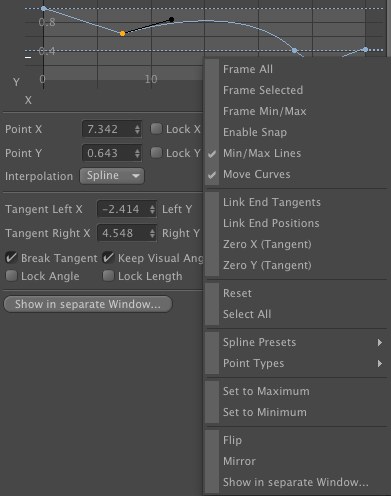
If you click on the small arrow to the right of the Function Graph’s name (or for nodes on the left in the Details tab), several additional settings will be made available.
The coordinates of a selected point will be displayed. These coordinates can be modified here.
Locks selected points to their current axis values.
Here you can select the interpolation type (curve shape) for selected points through to the next point:
- Spline: The curve can be given any shape using tangents
- Cubic: Produces a harmonious curvature through Spline points without overshoots
- Linear: A linear interpolation produces a straight line between points, i.e., the curve will have a kink at Spline points
If you right-click on the Function Graph window a context menu will open from which you can select numerous additional settings from the Point Types menu.
Here you can define the tangent end points numerically.
The following 4 options let you define properties for each point individually:
If enabled, the left and right tangents can be modified independently of each other.
If enabled, the angle between left and right tangents remain constant while the other tangent is being modified (as far as possible), i.e., the other tangent will move accordingly.
If enabled, only the tangent length can be modified.
If enabled, tangents can only be rotated around their origin.
The Function Graph will be opened in a separate, scalable window. This window can, for example, be scaled to fill your screen for very fine tuning of the graph.
 Spline presets can be saved for later use.
These commands can be used to save and load Spline curves.
Selecting the Save Preset command will open a small dialog window in which the preset name and other information can be defined.
Double-clicking on Load Preset will open a small selection window from which presets can be loaded.
Additional function graph settings for use with nodes
In nodes you will also find these settings exclusive to nodes:
Use this setting to affect the interpolation of splines. The higher the value, the stronger the point and its tangents’ effect will be (if set to 100%, the spline will run exactly through the point). Lower values will cause the spline to behave correspondingly more like a B-Spline.
Use these values to adjust the input and output values. This reflects the function of a Range Mapper.
Context Menu
Right-clicking on the Function Graph window (when Type is set to User) will open a context menu with the following options:
If you zoomed in to a specific region, this command will display the complete Spline Curve, including points.
All selected curve points will be displayed at maximum possible size.
If you zoomed in to a specific location, this command will display the entire Function Graph.
If enabled, spline points will snap to the grid.
Minimum and maximum Y curve values will be displayed as dashed lines.
If enabled, you can click exactly on the Spline Curve and drag the complete curve (if not enabled only if all points are selected).
If enabled, the curve (if moved horizontally as a whole) can be moved to the left or right via the function graph. Points that are pushed outside of the graph will re-appear on the opposite side.
Picture the first and last points melted to a single point. If enabled, this option creates an unbroken tangent pair, i.e., both tangents lie exactly opposite of each other on the same plane. This is often necessary for functions in which beginning an end transition into each other – for example a Sweep object with a closed Spline. Without this option enabled, a kink would appear where beginning and end meet.
If enabled, spline start and end points will always lie at the same height.
Sets the X or Y section of the tangent to zero. This will produce a vertical or horizontal tangent, respectively.
Sets an existing curve on a linearly ascending one with a start and end point.
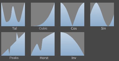
Here you can select from several preset Spline shapes, which will generate multiple spline points upon selection.
For Formula, see ![]() Formula.... Spline shapes can be defined via a formula that you type in.
Formula.... Spline shapes can be defined via a formula that you type in.
Here you can select from several tangent types for the selected points. This is explained with text and image examples here. These apply for both F-Curve points as well as for spline points.
Existing curves will be converted to a straight line at Maximum (Y=1) and Minimum (Y=0), respectively. All tangents will then run horizontally.
These commands mirror existing curves along a straight line that runs through Y=0.5 (horizontal mirror) and X=0.5 (vertical mirror) (each straight lines through the center of the Graph).
Function Graphs can also be copied and pasted to other objects / tools: right-click on the Function Graph name and select Copy. At the location at which the Graph should be inserted, right-click and select Paste from the context menu.
Color Gradients
To access additional gradient parameters, click the arrow next to the gradient.
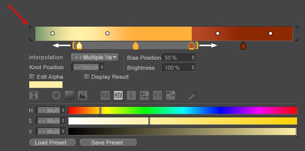
The knots or handles below the gradient are used to set the color and position of colors in the gradient. To add a knot, click in an empty area below the gradient and a knot of the color at that position will be added. To remove one or several knots, Drag & drop it away from the gradient (or simply press the Del key). To change the color of a knot, double-click it and use the Color Chooser (alternatively you can select a knot and open the Color Chooser using the arrow) that opens to pick the desired color. The diamond shapes on the gradient are bias handles and these pull the interpolation of the color knots from side to side for more control over how the gradient changes.
Handles/ Knots can, of course, be moved by clicking and dragging on them. If the Shift key is pressed simultaneously, the movement will be made in 5% steps.
Multiple Handles/ Knots can be selected (using Shift or Cmd/Ctrl keys or via right-click (the Shift kez must also be pressed)) and their properties will be displayed below. Orange brackets will be displayed, which can be clicked on and moved, through which all selected Knots will be selected in the distance in which they lie to one another. Clicking and dragging on a brackets will let you move all Knots together. If they are moved outside of the gradient’s outer borders, they will bunch up there (right-clicking on this "bunch" can be done to select one or more Knots). Multiple selected Bias Handles can also be moved together (drag one of the selected handles). Knots do not have to be selected for this.
Double-clicking on the gradient will select all Knots. One click will deselect everything. Double-click on the handle to display all settings in a separate window. If multiple handles lie on top of one another, you can right-click on them and select one from the list that appears (selected handles will be placed in square brackets).
The gradient can be moved or scaled horizontally (see below). For the latter, brackets will appear around the gradient (red marking at top of image). Clicking on these brackets will rescale the gradient back to 100%.
Selected Knots can also be moved using the cursor keys (left, right). Shift will also quantize this in steps of 5%. The up/down cursor keys adjust the Knot brightness (only legacy color gradient).
The following keys can be used to navigate within the gradient (similar to the Timeline):
- 1, MMB: Move (only possible for larger gradients)
- 2, mouse wheel, Alt + RMB: Zoom in/out
- S: Show selected
- H: Show all or scale all to 100%.
Right-clicking on the gradient will open a context menu with the following commands:
Invert Gradient
Inverts the gradient.
Double Knots
The number of Knots is doubled and changes the gradient accordingly.
Distribute Knots
Places the Knots and equal distance from one another.
Bias Handles
Enable this option if the Bias Handles (the small circles in the gradient) should be displayed.
Interpolation of all Knots
Lets the interpolation of all Knots be defined, independent of any current selection.
Size
Use this setting to define the vertical size of the gradient in 3 steps. This setting is also available in the Preferences menu (Units tab).
Interpolation
Smooth/ Cubic/ Linear/ Mix
The color transition takes place from the selected Knot to the next as defined by the small curves next to them. The Bias Handles are used to move the weighting to another color.
Step
No interpolation will take place. The color will change abruptly without transition at the location of the next Knot.
Knot Position
Use this setting to define the position of the selected Knot numerically. 0%=left, 100%=right edge.
Base Position
Use this setting to define the position of selected Bias Handles. 0%=left Knot, 100%=right Knot.
Brightness
This setting can be used to define the brightness of selected Knots in excess of 100%. Overly bright colors will be produced (HDR), which the color selector itself cannot produce.
This setting is not available for the use of color gradients in Nodes.
For several color gradients if used as control element (especially with PyroCluster), the following are also available:
Edit Alpha
Enable this option to edit the color gradient’s alpha channel.
Show Result
Shows the color gradient including its alpha channel. This color gradient will in fact be used in the scene.
Color gradients in Nodes
Color gradients that are used in Material Nodes have almost identical functions. They have an additional setting, A (for alpha), in their drop-down menu, which adds an alpha channel to the color gradient.
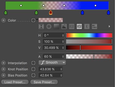
An alpha value can be defined for each handle. The combination of color and alpha will be displayed using a tiled background (see above).
In addition, handles can be linked to other Nodes, which can produce the following results and the handles will then also display a small connector icon:
If you right-click on the color gradient you can choose from the following additional settings:
Display
The following can be defined here:
- Bias: Enable this option of the bias handle should be displayed
- Alpha: Enable this option if the color and alpha should be displayed in combination
- Alpha Only: Enable this option if only the alpha should be displayed as a grayscale
Reset to Default
Sets the color gradient back to a black-to-white gradient without alpha.
Load Preset
Save Preset
Using these commands, gradients can be loaded or saved as presets.
Clicking on the Load Preset button will open a small dialog window in which the desired preset can be selected.
Collaboration with the Color Chooser
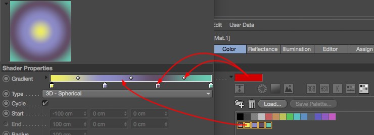
Colors or color fields can be dragged directly into a gradient. The following functions are available:
- An individual color or color field can be dragged onto a knot or bias know and the color will be replaced and the bias knot will be converted into a normal knot. If a color or color field is dragged onto an empty area of the gradient, a new knot will be created.
- If you drag multiple color fields into the gradient, a gradient consisting of all these colors will be created and all existing knots will be replaced.
Context menu for right mouse button
If you:
- right-click on a setting or
-
click and hold on a keyframe button
the context menu will open. This menu can, among other things, be used for creating keyframes for keyframe animations for a selected setting. These are the following functions:
The Attribute Manager’s context menu
To access the Attribute Manager’s context menu, right-click (Windows) or Command-click (Mac OS) a parameter or click and hold on a keyframe button. Using the commands on the context menu, you can record keyframes, create set driven keys and much more. Animate without ever looking at the Timeline!
Animation
Records keyframes for the selected parameters at the current frame (as indicated by the time slider). Alternatively, Ctrl-click the circle next to one of the selected parameters’ names.
Moves the time slider to the next/previous keyframe (if present) for the selected parameters.
Deletes all of the selected parameters’ keyframes at the current frame. Alternatively, Shift-click the red circle next to one of the selected parameters’ names.
Creates tracks for the selected parameters.
Use these commands to copy tracks between parameters. First, select the parameters whose tracks you want to copy. Choose Copy Track. Next, select the parameters that should receive the tracks and choose Paste Track.
Deletes all tracks of the selected parameters. Alternatively, Ctrl-Shift-click the circle next to one of the selected parameters’ names.
Track Modifier- Add Tag
This command can be used to add a Track Modifier tag , at which point the Tracks will be recorded (Include tab).
Shows all animation tracks of the selected parameters in the Timeline.
Shows all F-Curves of the selected parameters in the F-Curve manager in the Timeline.
To create a keyframe selection, select several parameters and choose Add Keyframe Selection. The selected parameter names will be colored to indicate that they belong to the keyframe selection. When you use Cinema 4D’s Autokeying mode, only parameters in the keyframe selection will be recorded (provided their values actually change).
For example, if you define the color of a light as a keyframe selection, the subchannels will be highlighted, not the light itself. The same applies to all parameters that have subchannels.
Removes the selected parameters from the keyframe selection.
Deletes all keyframe selections for the selected objects.
Using these commands, you can create set driven keys directly in the Attribute Manager without having to open the XPresso Editor. A set driven key uses one parameter to drive (i.e. control) another parameter. For example, you might use a set driven key to make a car’s electric windows wind down when a character presses the switches. Almost any type of set-driven relationship is possible, making it easier to manage complex motions or objects.
For example, let’s say you have two objects, a cube and a sphere, and you want the cube to always be at the same x-position as the sphere. Proceed as follows:
-
Select the sphere in the Object Manager
-
Enable the Position.Y parameter in the AO Manager, then right-click on the parameter
-
Select Set Driver from the menu that appears
- Repeat steps 1-3 with the cube but select Set Driven (Absolute) in step 3.
Done. Cinema 4D will automatically generate three nodes in the Node Editor: Sphere and cube, whose Position.Y parameters are linked via the Range Mapper Node. Using the Range Mapper (see Calculate (Group)) values within a certain range can be passed to values within other ranges (e.g., a brightness of 0-100 to a Position.Y range value of 34-2387).
Set driven keys also enable you to drive object parameters using your own sliders. To learn how to create your own sliders, look up User Data in the index.
With Absolute, the driven parameter uses exactly the same value as the driver. For example, if one object drives the height of another, the driven object will move to exactly the same height as the driver.
Relative, on the other hand, only passes on relative changes from the driver to the driven parameter. For example, if the driver object is moved up 10 units in relative mode, the driven object also moves up 10 units from wherever it happens to be in the scene. Suppose the driver object has an initial height of Y=1,000 and the driven object an initial height of Y=0. If you move the driver object to a height of 1,050 (a change of 50 units), the driven object also moves up 50 units, to Y=50.
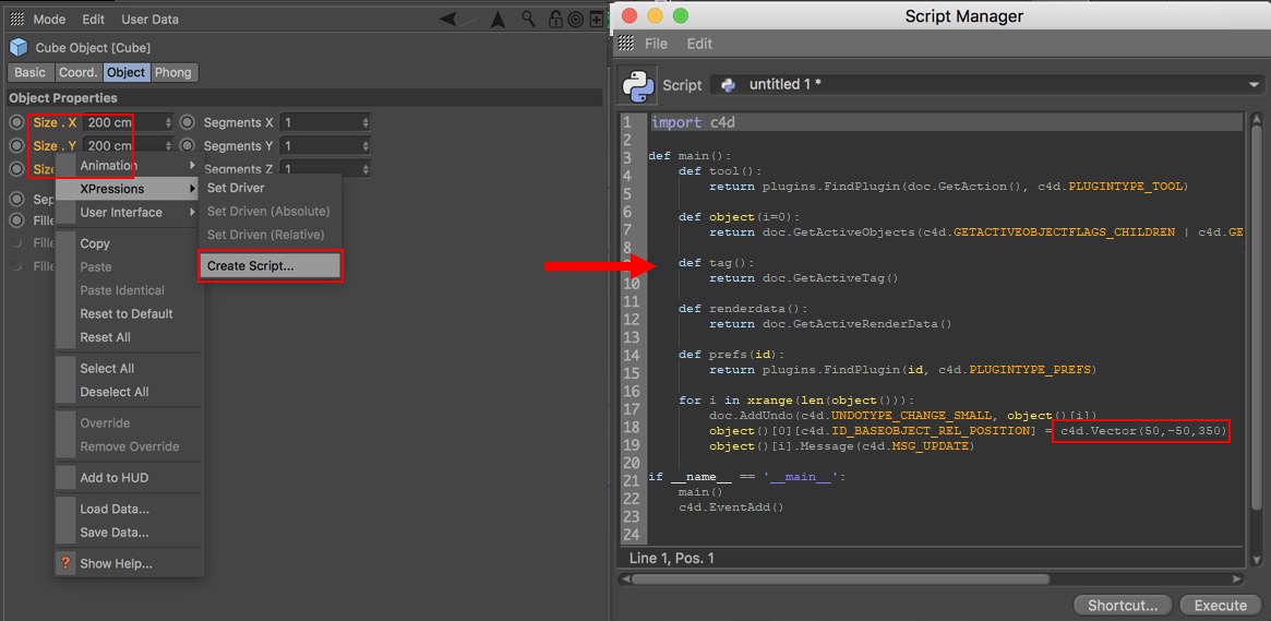 This script sets a selected object to a specific position (50, -50, 350).
Use this command to create Python scripts that define specific parameter values. All parameters selected in the Attribute Manager will be output as Python scripts in the Script Manager.
This code can also be used in other scripts. For example, defining parameter values as a type of tool preset. Another use would be for the Render Settings: Select the desired parameters, execute the Create Script command and place this script (see Script Manager) in the form of a command somewhere into the layout. This lets you create Render Settings with a single click (if you prefer not to use the menu).
If you have used the Attribute Manager’s Add User Data command (User Data / Add User Data) to create your own sliders or other GUI elements, use Edit Entry to edit these GUI elements. For example, you can change the minimum and maximum values for sliders.
To delete a slider or other GUI element that you have created, select the element and choose Remove Entry.
Additional Parameters
This sub-menu appears when only one parameter is selected. It allows you to adjust the parameter’s interface. For an existing parameter, you usually have a choice between a numeric text box (Float), a slider (Float Slider — No Edit Field) or a combination of both (Float Slider).
To control the minimum and maximum values of user-defined sliders, choose the Edit Entry command and in the dialog that appears, set Min and Max to the desired values.
The values entered here will be saved and applied as default values to each object.
Some elements, such as color fields, can also be displayed numerically.
Parameters displayed in the Attribute Manager for various objects, tags, etc., can be copied via right-click and selecting the Copy User Data Interface command and pasted (context menu) as User Data for any object that is displayed in the Attribute Manager (see also User Data)
Use these commands to copy values between parameters. Select the parameters whose values you want to copy. Choose Copy. Next, select the parameters that should receive the copied values and choose Paste.
Suppose there are two cylinders in the scene. You select one of the cylinders, select its Radius and Height parameters in the Attribute Manager and choose Copy to copy the two values. If you then select the other cylinder and choose Paste Identical, the two values will be pasted to the same parameters — Height and Radius — regardless of which parameters are currently selected. This is in contrast to the Paste command, which pastes to the selected parameters.
This command sets all selected parameters back to their default values (i.e. the values they had upon creation).
Use this command to save the selected setting as a partial preset. This is a restricted parameter selection that can later be transferred to the selected element when the preset is selected. Other settings remain unaffected.
Select or deselect all parameters.
The Save Data command enables you to save the values of the selected parameters. This is especially useful for saving complex spline graphs.
To add a spline graph as user data, in the Attribute Manager choose User Data / Add User Data and in the dialog that opens, set Data Type to Spline and click OK. The spline graph appears below the existing parameters.
To load saved data, select the parameters that should receive the data and choose Load Data. Use your system’s file selector to choose the data file. The saved data and the selected parameters must be of the same data type. For example, you cannot load real values into parameters whose data types are set to Integer.
This and the next menu item will only be made available if a Take other than the Main Take is selected in the Object Manager. Selecting this command will let the respective setting be overridden. Alternatively (note also using the Override function for overriding settings) the setting can simply be dragged and dropped into the Take Manager.
Details about the Take system can be found here.
This command cancels the override of the current take and will re-apply the settings of the parent Take.
Adds the selected parameters to the HUD. For a description of the HUD, look up HUD.