Object Properties
There are two types of Volumes (depending on which is selected, either Boole or blend options will be available in the Object List):
This Volume type (SDF) can be used when a Boolean operation has to be applied when modeling. What does this Volume type do? Polygons, points and particles themselves have no volume. In order to generate volume, layers of Voxels are placed around these elements (over and under polygon surfaces). The Voxels are arranged in a Voxel Grid:
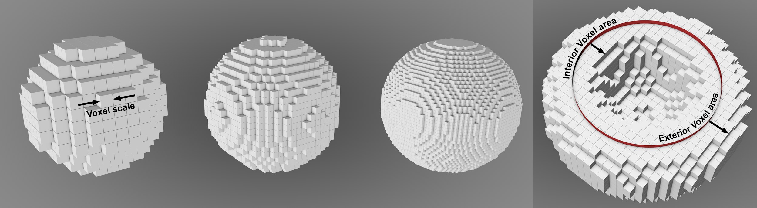 Left section: the smaller the Voxel Size, the more precise the sphere’s shape is; Right: Voxel layers are generated on the shape’s inner and outer surfaces.
Each Voxel’s value reflects its distance from the polygon surface.
Note the Volume Mesher’s Voxel Range Threshold setting, which will again make a polygon surface from the Voxels. The polygon surface can only be generated within the Voxel layers (i.e., the actual Volume).
This Volume Type is primarily suited for rendering fluids, fire, fog and smoke (you can load smoke and fluids simulations from third-party applications).
What does this Volume type do? Simply put, it fills closed volumetric polygon objects entirely with Voxels. When working with particles, splines or points, Volumes are generated around the points using a scalable radius.
A value between 0 (outer) and 1 (inner) is saved for each Voxel. How precisely the value range is distributed is defined by the Inside Voxel Falloff setting.
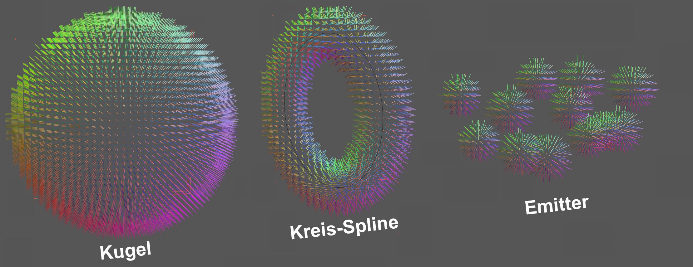 3 object types are converted to vectors.
This option is somewhat different from the two previously described options. Here, Volume Vectors and not voxels are created for modeling. This is a spatial distribution of vectors.
The Voxel Size setting also plays a role here because all vectors withing a voxel are identical with regard to value and direction, which defines the "resolution" of the Volume Vectors.
In the viewport, these Volume Vectors are displayed as follows by default: one vector is shown per voxel and is colored according to its direction (in the Volume Builder’s object coordinate system: +X, +Y, +Z in the usual colors, -X turquoise, -Y dark violet, -Z ocre and the corresponding in-between values). In the viewport’s Option menu under Volume Vectors you will find additional options for displaying Volume Vectors.
All settings described here for arranging/distributing voxels also apply to vectors. Voxels can contain all types of values for modeling purposes, for example (if Volume Type] is set to Signed Distance Field) the distance from the surface.
A limited voxel view around a polygon surface, e.g., for a sphere, leaves the center of the sphere "free of direction" - null vectors lie here.
Another functionality within Cinema 4D - Fields - can also be used to control vectors spatially. What are these Volume Vectors good for? You can, for example, control forces using the Field Force.
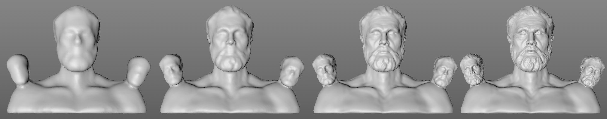 Decreasing Voxel Size values from left to right.
Use this value to define the Voxel size, i.e., the Voxel grid resolution, in centimeters. The smaller the value, the more precise the result and the longer the render times will be.
If you enter values that are too low, a warning prompt will be displayed. If the value is too large, it will be increasingly difficult to work with the Voxels.
The following 4 settings apply to the Volume Type SDF.
Interior Voxel Range[1..2147483647]
Exterior Voxel Range[1..2147483647]
Use these settings to define the number of Voxel layers should be generated on the inner and outer areas (see image here: Volume Type).
These settings are used in conjunction with the Volume Mesher’s Voxel Range Threshold setting. A mesh can only be generated between these two Voxel ranges (i.e., within the actual Volume).
The Interior Voxel Range is applied towards the object’s interior. If you want to affect the object’s interior sides using the Reshape Filter (e.g., with Noise falloff), this value must be increased:
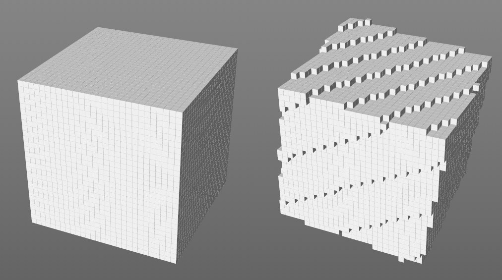
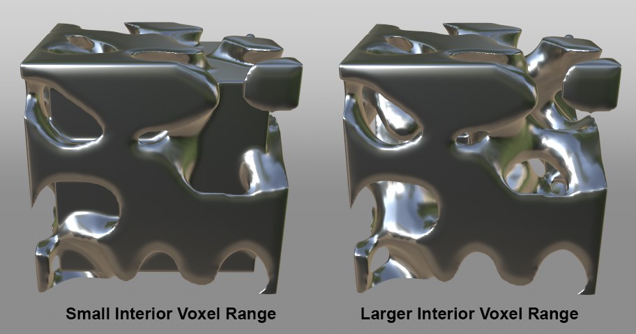 Different values applied for volume definition on a cube.
Note, however, that the speed of calculation will slow correspondingly with increasing values. The Volume filters can also be used to affect Voxel layers (see here).
Spline Voxel Range[1..2147483647]
So you don’t have to create a Sweep object to create a tubular volume using a spline, overlapping spheres are placed along the spline, combined and then Voxel layers are placed around interior and exterior of the structure. The Spline Voxel Range setting defines the number of Voxel layers on the interior and exterior of the surface.
Particle Voxel Range[1..2147483647]
The Volume Builder places a sphere next to each particle, around which in turn Voxel layers are placed. The Particle Voxel Range setting defines the Voxel layers on the interior and exterior of the surface.
This is the heart of the Volume Builder. This list contains all objects out of which a Volume should be built. For multiple objects, you can determine how these should be Booled (SDF) or calculated (Fog).
If you make an object a Child object of the Volume Builder, this object will automatically be added to the list and hidden in the Viewport. You can also drag objects into the list (these may have to be hidden manually).
The objects will be evaluated from the bottom to the top of the list. The elements in the list can be re-arranged via drag & drop. A new folder can also be created.
The usual selection functions can be used: drag a selection box to select multiple elements, use the Shift and Ctrl/Cmd keys to select or deselect a series or individual elements, etc. When an element is selected, additional settings will be displayed in the menu below.
The Objects list can be compared to the layer structure of an image editing program, where the evaluation of layers also runs from the bottom to the top. A subsequently added layer affects the previous layer using a modifiable mode (like the mix or blend mode in an image editing program.
To continue with this analogy, a Volume Filter can be placed in the same folder as the layers it affects and the effect of Volume Filters can also be masked using linked fields (Field tab).
The Objects list has the following columns:
- Enable/ Disable: Use this option to include or exclude elements from the Volume Builder (the object’s visibility in the Viewport will also change if it’s a Child object of the Volume Builder)
- Name: The respective object’s name
- Mode: Different Boole or blend options, depending on the Volume Type defined (details: Modes).
- Input Type: Depending on whether the respective object is a Child object of a Volume Builder or was dragged from a different hierarchy (linked), the object will be classified accordingly. Child objects will, when removed from the list or deleted, also be deleted from the Object Manager (this will not happen with linked objects!).
Objects can appear double in the list. What’s this good for? This is often a requirement for complex Boolean operations in which numerous results are in turn combined with other Booles:
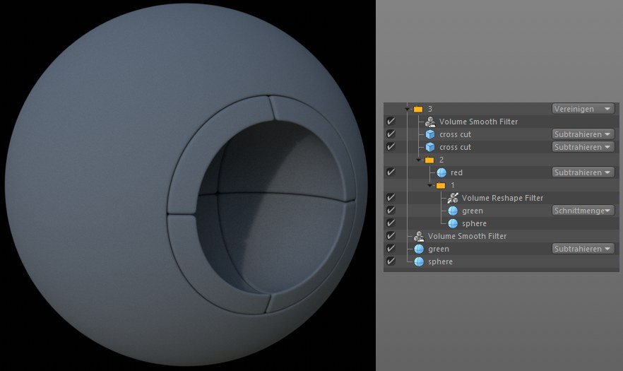 The objects Green and Sphere are used twice even though they appear only once in the Object Manager.
List Element Settings
Depending on the type of object in the list and which Volume Type is defined, the following settings will be displayed when the respective object is selected, i.e., not all settings described below will always be displayed.
The following types of objects can be added to the list:
- Polygon objects or their Generators
- Spline or their Generators
- Matrix objects and particles (use the particle group for Thinking Particles)
- Fields and Falloff objects (the latter has a Field list in its Fields tab in which not only Fields can be combined but effect layers can also work; the Group Field works the same way)
- Other Volume objects (whose Voxel values have to be combined for the Voxel Builder’s Voxel values, which can result in longer calculation times)
Volume Filter Layer
Use these settings to create a Volume Filter (depending on the volume type, different filters will be made available; this is the same Filter object only with different settings. These can be found in the main menu under Volume/ Signed Distance Field Filters, Fog Filters and Vector Filters). These filters will not be created as objects in the Object Manager but will only exist here in the list. Contrary to the Filter objects, these have a reduced parameter set (e.g., the Coord tab will be hidden because its properties are irrelevant or will be assumed by the Volume Builder object).
These Filters can, however, be generated and dragged into the list just like objects. The functionality is the same.
The Filters affect elements arranged above them in the list.
Folder
Creates a folder that has a Mode assigned to it. A folder can have the following uses:
- Restrict a Volume Filter’s effect to specific objects or object groups
- Create a better overview
Elements will also be evaluated from bottom to top within a folder.
Cache
Clicking on this button will create a Cache Layer in accordance with the elements selected in the list.
Blend Modes
Modes when using Signed Distance Field (SDF)
In this mode, Boolean operations can be executed.
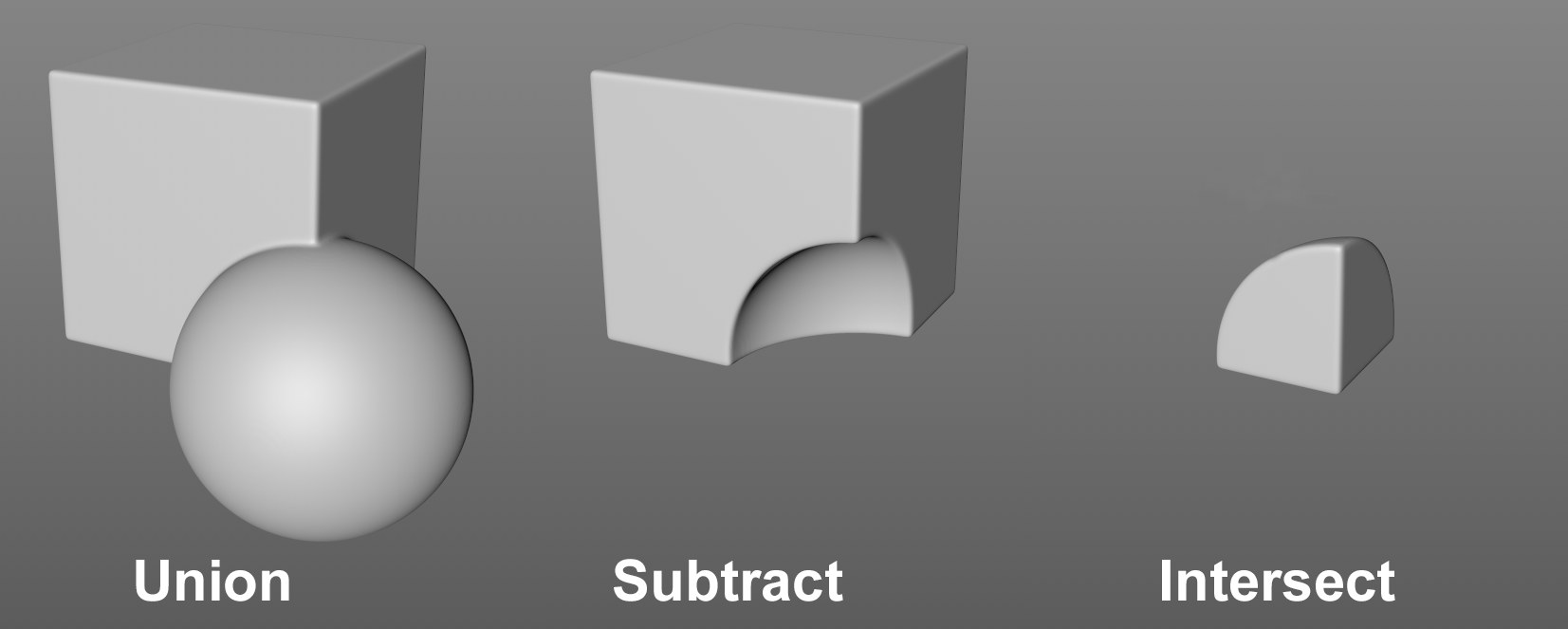 The effects of the modes for partially overlapping objects (the sphere lies below the cube in the list).
The following modes are available:
- Union: The object to which the mode is assigned will be combined with the object arranged above it in the list
- Subtract: The object to which the mode is assigned will be subtracted from the object arranged above it in the list
- Intersect: Only the intersection of the object to which the mode is assigned and the object arranged above it in the list will remain
Modes when using Fog
Each Fog Voxel saves a float comma number as a value. The modes that can be defined here do nothing more than calculate these values mathematically. For example, if the Min mode is selected and Volume A puts out a value of 7 and Volume B a value of 5 for the same Voxel, the result will be 5. If Max is selected, the result would be 7 and with Add 12, etc.
Normal will simply overwrite the Voxel values of the object arranged above it in the list with the values from the object to which the Voxels are assigned. In the example above, the result would be 5. How this works in conjunction with the Falloff object can be read here.
The calculations are not particularly descriptive - testing together with a Volume Mesher can produce faster results.
Modes for use with the Vector volume type
If you want to blend vectors, you can select from the following options:
- Normal: The list element that defines the mode overwrites the underlying modes.
- Add/Subtract: Vectors will be added or subtracted.
- Cross: This special mode ascertains a direction perpendicular to the plane that spans both vectors to be blended. Directions that are tangential to polygon surfaces can be realized:
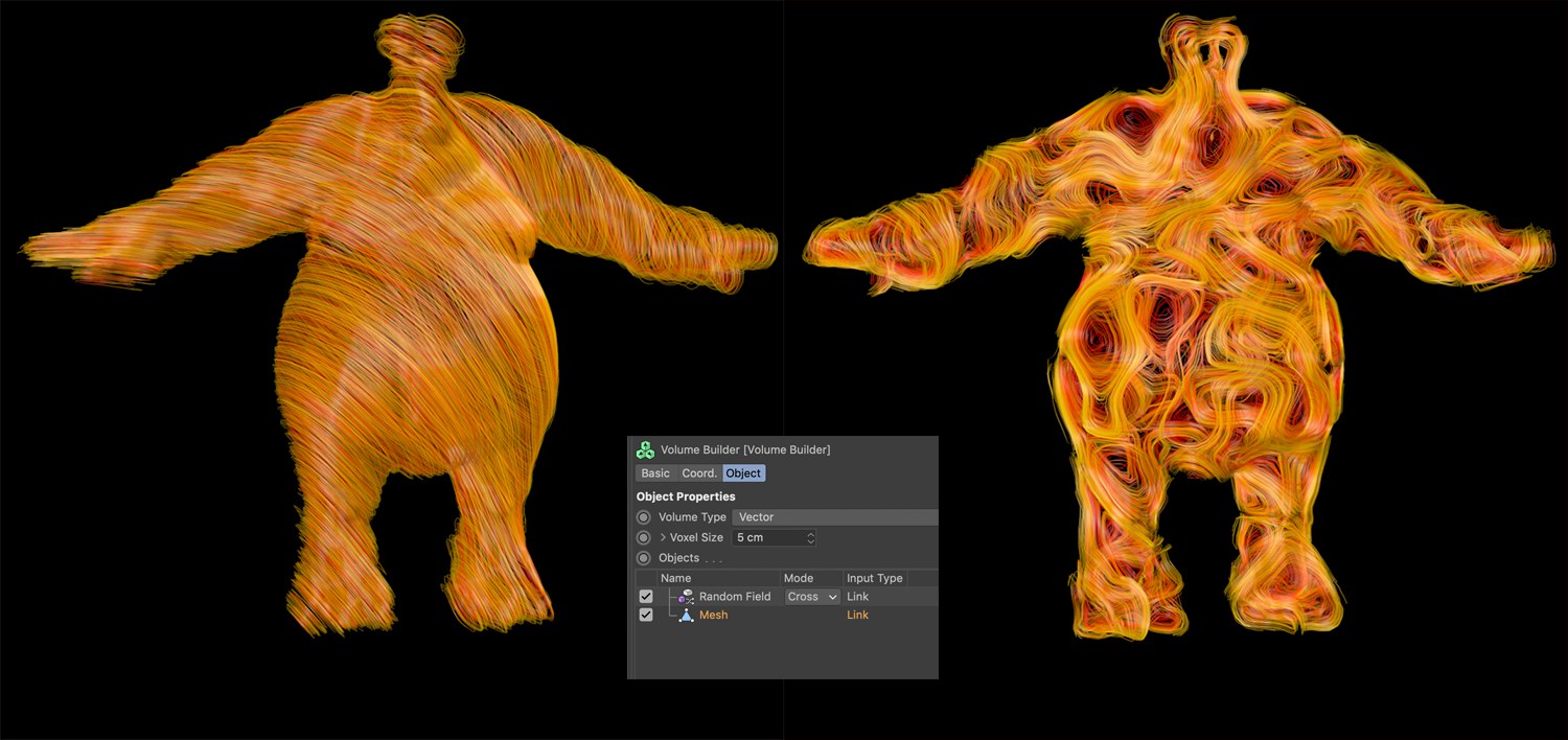 A Noise Random Field is blended with a mesh in Cross mode. The vectors that run tangential to the surface of the mesh use a Field Force to control the force on a particle (whose path is in turn converted to splines by a tracer) created by a matterwave node.
 Converting a cube to Voxels: left with the default grid, right rotated.
When generating Voxels, a grid made up of cube-shaped grid cels is used. By default, this grid lies at the object origin with no rotation. Drag another object onto the grid to define its origin and orientation for the Voxel Grid. So, what’s this good for?
When the Volume Mesher creates a mesh from the Voxels, artefacting can occur during interpolation. Assuming you have 3 cubes at different positions, for example. Depending on the position, one cube’s edge can be very sharp because it lies on the edge surface of two Voxels and the other cube’s edge looks rounded because it runs through the middle of a Voxel. In such cases it can be useful to overwrite the default Grid Matrix to round both edges.
Another possible use would be the animation of an object group using the static Grid Matrix. This will cause cracks in the geometry (especially obvious when using larger Voxel Scale values). If you drag the grouping Null object, for example, into the Override Grid Matrix field, the Grid Matrix will move as well and no cracks will occur.
This button will be displayed if a Volume object or Volume Builder is placed into the Override Grid Matrix field. What does this button do? It sets the Voxel Scale of the Volume Builder to that of the placed (Volume)object. This synchronizes the Voxel scales (the direction is already correct because of the Override Grid Matrix function) and the calculation is optimized to be as fast as possible. In other words: no re-sampling is necessary because the Voxels lie exactly on top of one another.
Depending on the scene’s complexity, working in the Objects list can be quite arduous, for example, if all Boolean operations have to be calculated when a Boole mode is changed. This automatic recalculation will always take place if the Auto Update Settings option is enabled. If you want to quickly make several changes you should disable this option before doing so. After the changes have been made you can click on the Update button (see below) to recalculate the Objects list.
Click on this button to recalculate the Objects list. Enable the Auto Update Settings option if you want this done automatically.
Infos
At the very bottom of the menu, the total number of active Voxels and the approximate memory requirement for the object currently active in the Objects list are displayed.