Mesh Checking
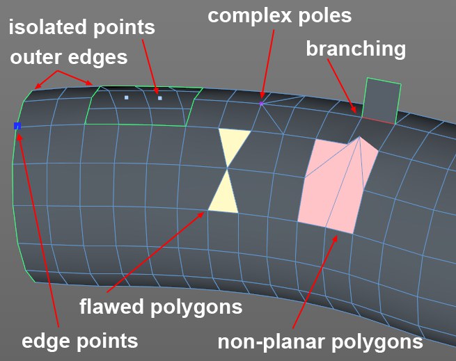
 Examples of faulty elements. Both faulty polygons each have 2 congruent ponts.
Polygon meshes need to meet certain standards depending on the intended purpose (e.g., 3D printing). Therefore, it would be very useful if a tool were available that displays faulty elements. This is exactly what the Mesh Check command does (located in the Attribute Manager’s Mode/Modeling menu). Faulty elements will be shown in specific colors on selected polygon objects. These elements are counted and can also be selected. This can also take place in realtime so the faulty geometry is displayed while the mesh is being created.
The mesh check only counts triangles and quads, i.e., if you have an uneven N-Gon made up of 7 triangles, the check will also display 7 uneven polygons (even if these are partially even).
Enables or disables mesh checking.
Enable this option if points that do not belong to any polygon (e.g., those remaining after a polygon surface has been deleted) should be colored accordingly.
Using the Color function, flawed elements can be marked accordingly in the Viewport.
Select switches to the correct element mode and selects flawed points, edges or polygons.
Enable this option if points that belong to more than 5 polygons should be colored accordingly.
Using the Color function, flawed elements can be marked accordingly in the Viewport.
Select switches to the correct element mode and selects flawed points, edges or polygons.
Enable this option if points that lie on an N-gon edge (Viewport: Filter / N-gon Lines (the turquoise lines)), and meet the criteria described in the Point Threshold description below, should be colored.
Using the Color function, flawed elements can be marked accordingly in the Viewport.
Select switches to the correct element mode and selects flawed points, edges or polygons.
Edge Points Angle Threshold [0..180°]
The points mentioned in the previous description will first be marked when the angle to the neighboring points deviates by this value at the maximum. This means that if you have N-gons that have too many points, i.e., points that lie on edges but have no effect on the object’s shape, these can be deleted. This setting can be used to locate these points.
For Complex Poles, this setting defines the minimum number of converging edges required to constitute a complex pole.
Enable this option if edges that belong to more than 2 polygons should be colored accordingly.
Using the Color function, flawed elements can be marked accordingly in the Viewport.
Select switches to the correct element mode and selects flawed points, edges or polygons.
Enable this option of edges that belong to only one polygon should be colored accordingly.
Using the Color function, flawed elements can be marked accordingly in the Viewport.
Select switches to the correct element mode and selects flawed points, edges or polygons.
Enable this option of collapsed polygons or polygons with congruent points should be colored accordingly.
Using the Color function, flawed elements can be marked accordingly in the Viewport.
Select switches to the correct element mode and selects flawed points, edges or polygons.
Not Planar Polygons
Color
Select
Enable this option if points whose points to not all lie on a plane should be highlighted.
Using the Color function, flawed elements can be marked accordingly in the Viewport.
Select switches to the correct element mode and selects flawed points, edges or polygons.
This threshold value applies to Uneven Polygons and defines the minimum angle (i.e., when the angle of triangulated quads and N-Gons to neighboring polygons exceed this value) at which an uneven polygon should be marked as such.