![]() Connector
Connector
Connector
Connectors restrict the movement/rotation of Rigid Bodies and Soft Bodies. Hence, Connectors can only be used on objects to which a Dynamics Body tag has been assigned.
Without Connectors, Rigid/Soft Bodies would only be affected by forces and collisions. For example, it would be very difficult to simulate a simple hinge function. With a Hinge Connector, this is not a problem at all.
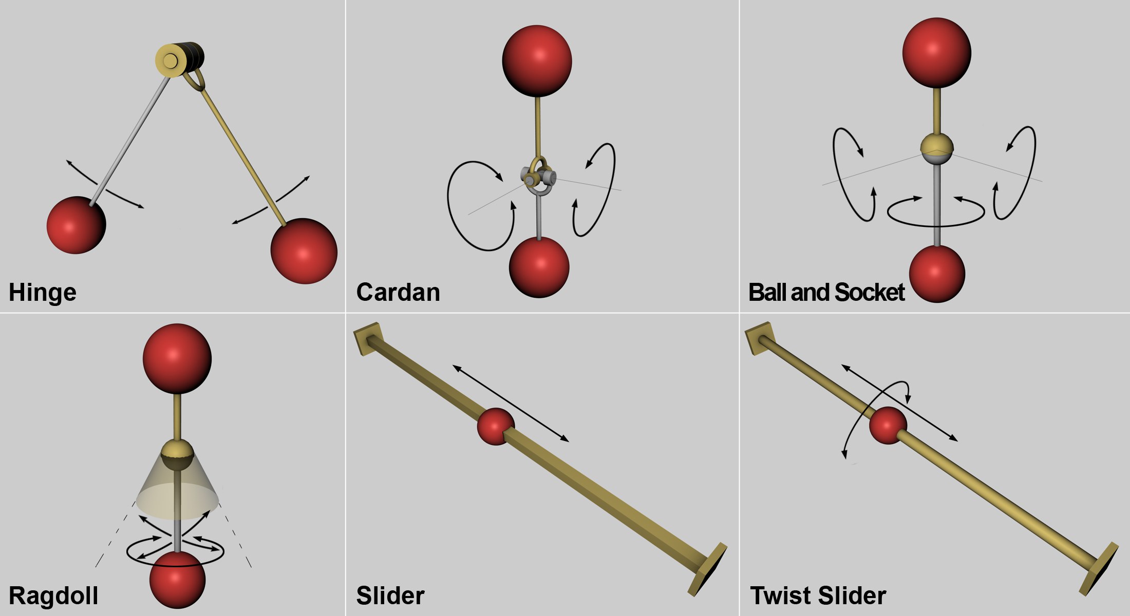 Several available Connectors. The arrows show the direction in which the objects can be moved or rotated. The movement characteristics of those not shown - Planar, Box and Wheel Suspension - are basically combinations of the above.
Connectors are displayed in the Viewport in a manner that lets you easily recognize which motion/rotation that particular Connector has to offer. Connectors that will not function (e.g., if the Dynamic option is disabled or if at least one object that has been assigned a Dynamics Body tag) (or the objects in question have not yet been affected) will be displayed in red.
- Select Connector from the main menu:
- Move or rotate the Connector into position in the Viewport (where you want the hinge to lie or parallel to a slider’s axis)
- In the Connector’s parameter settings (Object tab), use the Object A and Object B fields to link the objects with the Body tags.
The Connector position and orientation are important!
These settings define the movement and rotation axes. If you take a look at the image above, the direction in which the spheres attached to the Hinge can rotate are defined by the position of the hinge. The same is true for the Slider Connector, whose position defines the direction in which the sphere can travel.
A hinge will most often be placed along a rotational axis. Take a look at the following simple scene that contains 2 cylinders and 2 cubes, each with a Dynamics Body tag:
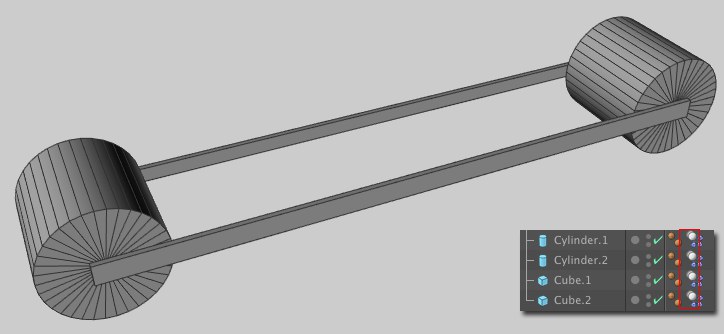 These four primitives will be used to create a functioning vehicle.
Without Connectors, these elements would simply fall apart without interacting with each other (aside from coincidental collisions). In order to make a functioning vehicle you will need four Hinge Connectors that connect the two cubes to the rotational axes of the cylinders. Create 4 Hinge Connectors. Two will be attached to the first cylinder’s rotational axis and two will be attached to the second cylinder’s rotational axis (the Transfer function will be very useful for this). It doesn’t matter where along the rotational axis the Connectors lie - these can be moved in accordance to the axis without affecting the functionality itself. For organizational purposes, however, it’s better to position them at their intended location. In this example it would be where the cubes connect to the cylinder. Subsequently you have to link the cylinders and cubes (of course at the corresponding points of rotation) in the Connector settings (Object tab);:
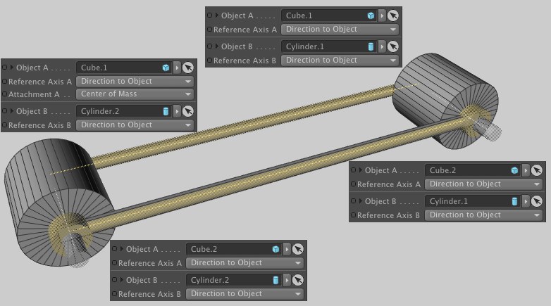
You have already almost created a functioning vehicle that can, for example, roll down a sloping plane. The 4 objects create a whole object with rotating cylinders. This vehicle could now be combined with an actuator such as a Motor, which would allow the vehicle to also drive up an incline.
2 Connectors can also be combined, e.g., a Slider can be linked to a Hinge, as in the following example:
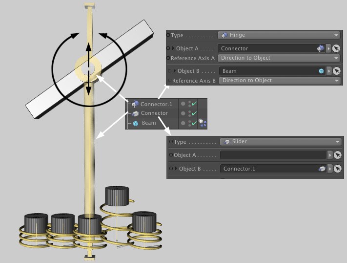 A Hinge Connector linked with a Slider Connector.
The springs at the bottom, whose state of rest changes randomly, toss the beam into the air. The "Connector" makes sure the beam only moves in a vertical direction. In order to let the beam rotate as well, it was also linked with a Hinge Connector ("Connector.1"). That’s all you need to create this perpetual work of art.
The direct combination of 2 linear (e.g., Slider) or rotational (e.g., Hinge, Cardan, Ragdoll, Ball and Socket) Connectors is not possible, due to mathematical restrictions.
Generally speaking you should avoid combining too many Connectors. Otherwise the structure of the combined elements can become very confusing. Normally all moving parts in a given scene are modeled and individual Connectors will suffice for the creation of the desired motion. The wheel of a car, for example, is attached to the car’s axle, around which it also rotates. A simple Hinge Connector is all you need to achieve the desired functionality.
Duplicating objects linked with Connectors
A complete Dynamics system, including Connectors, Spring and Motors and their linked elements, can be duplicated. To do so, all elements should be placed within a common Null Object and this in turn made a Child object of the generator.
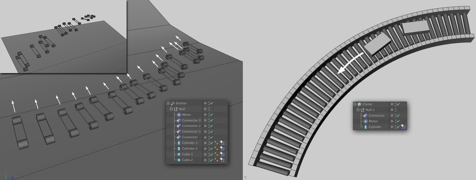
At the left of the image above a vehicle was equipped with a Motor and the entire construct was made a Child object of an Emitter. The Emitter sets the vehicles free so they can putter around independently. At the right is a simple cylinder, also propelled by a Motor and cloned in a curved shape using a Cloner object. The result is a working conveyor.
Make sure to give the collision objects that are not affected by Dynamics (such as the plane at the left or the tracks at the right) the correct shape (most often Shape
If you have the impression that the Connectors are not doing exactly what they are supposed to you can turn your attention to the Dynamics calculation’s parameters that control precision. The most important of these are: Steps per Frame, Maximum Solver Iterations per Step and Error Threshold.
Another reason for imprecision can be a large difference in the mass of the objects (this also occurs if Shape has been set to Off in the Dynamics Body tag’s Collision tab!). Physical simulations generally don’t like this.