Object Properties
A Connector behaves differently based on the option selected in the Type menu. Each option contains its own specific parameters.
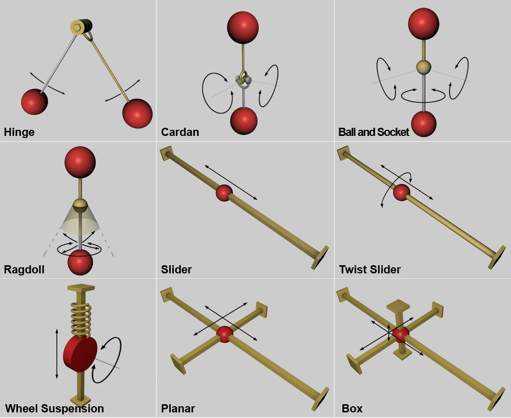 Possible directions of movement of various Connectors.
A Hinge only allows rotational movement in a single direction around its center. The rotational movement only takes place on the plane defined by the Connector’s X and Y axis. The rotational angle can be limited, if desired.
A cardan joint is basically made up of two hinges that are attached at a 90° angle to each other. This allows for relatively complex movement. Cardan joints are typically used to transfer torque at angles. In order for this to function, the following conditions must be met:
- The rotational axis of both connected objects must intersect
- The Connector must lie exactly at the point of intersection of both rotational axes
The cardan joint’s rotation can be limited in either direction, if desired.
A ball and socket joint can be rotated in 3 dimensions. An example of a ball and socket joint is the human shoulder joint.
A Ragdoll Connector is a ball and socket joint (see above) whose rotational angle can be limited within a cone-shaped area. A rotational limit can also be defined for the vertical axis of object B.
The name "Ragdoll" reflects the function of the Connector: it can be used to create human joints such as hip and shoulder joints:
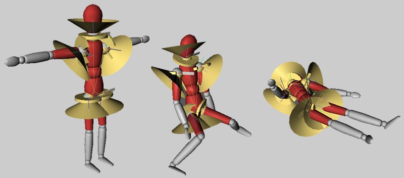 Use the Ragdoll Connector to create natural human joint movement.
A Slider restricts movement to the Connector’s Z axis.
The freedom of movement can be restricted along the length of the axis.
A Twist Slider restricts movement to the Connector’s Z axis. This Connector also lets you rotate around the Slider’s axis. The freedom of movement is restricted to the length of the axis and the rotation around the axis.
A Planar Connector only allows movement on the Connector’s X-Y Plane. Movement can take place in all 4 directions.
A Box Connector allows movement in all directions and can also be restricted in all 6 directions.
This mode is a little different from the rest. It allows movement in the Connector Y direction as well as rotation around the Connector Z axis. As such nothing special but this mode also has a spring effect (along the Connector Y axis). This lets you quickly and easily create dynamic spring effects for wheel constructs that can even include steering - perfect for wheeled vehicles!
This mode restricts all movement completely and lets you basically nail one object onto another.
Another option would be not to connect objects via a Connector but make one object a Child object of another and use the combined objects as a Dynamics object (Inherit Tag
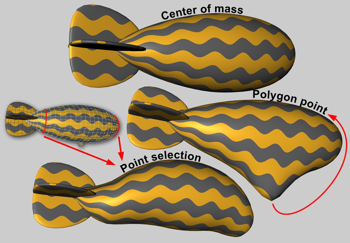 An ascending Zeppelin is being held in place using a Connector with various restraining lines.
Wherever forces guide an object, the point on the object at which this occurs is important. For example, if a motor that pushes a Hard Body object along is located at that object’s center of mass, the object will be moved in a straight line (in the absence of any other forces). If the force affects the object outside of its center of mass, torque will automatically be generated and the object will rotate.
Soft Body objects, however, behave differently. Each object point is connected via springs to other points. If a force affects only a single point an unwanted result can be produced. However, the effect can be spread to larger regions:
The Attachment A and Attachment B parameters are available for the following Dynamics objects:
- Connectors
- Motors
- Springs
This option contains no additional settings. The force is generated at the center of the given object’s mass. No deformations will occur on Soft Body objects.
This option lets you select a specific object point at which the force will have its origin. The Region of Influence value lets you increase (or decrease) the region around this point within which the force will affect the object. This is only relevant for Soft Body objects and has no effect when applied to Rigid Body in conjunction with Connectors.
Force can also be applied via Maps (Point Selections tag oder Vertex-Maps). Additional parameters will be made available with which you can, for example, adjust the degree to which the selected (or weighted) points can be affected.
Object fields A and B can be found in the following Dynamics objects:
- Connector
- Motor
- Spring
These 3 objects each connect 2 objects using different methods.
Both objects can be dragged into the Object A and Object B fields, respectively. If one of the Object fields is left empty, the following will result:
- Connectors: Position and rotation of the Connectors are fixed (otherwise the Connector would move/rotate with the objects).
- Motors: The basic principle "action = reaction" no longer applies. Force and torque are generated autonomously (see below).
- Springs: One of the springs will lie in the world coordinate system’s origin.
Except when using the Ragdoll and Wheel Suspension modes, it does not play a role in which order the objects to be connected are dragged into the Object A and Object B.
If an Object field is left empty when using Motor Dynamics: According to the laws of physics (actio=reaction), when one body exerts force on another, the second body exerts a collinear force on the first equal in magnitude but oppositely directed. This condition is met when each field contains an object. A good example is that of a helicopter: The rotor blades are driven by a motor and rotate accordingly. Simultaneously a colinear force is exerted on the helicopter’s fuselage. The tail rotor compensates for this - otherwise the fuselage would rotate around its vertical axis.
Reference Axis A
Reference Axis B
Reference axes are needed wherever a rotation needs to be measured, as is the case with a Connector with a rotational movement and a rotational spring. In both cases, the rotational movement can be restricted to a specific range. Both the Connector and the rotational spring must lie on the same rotational plane.
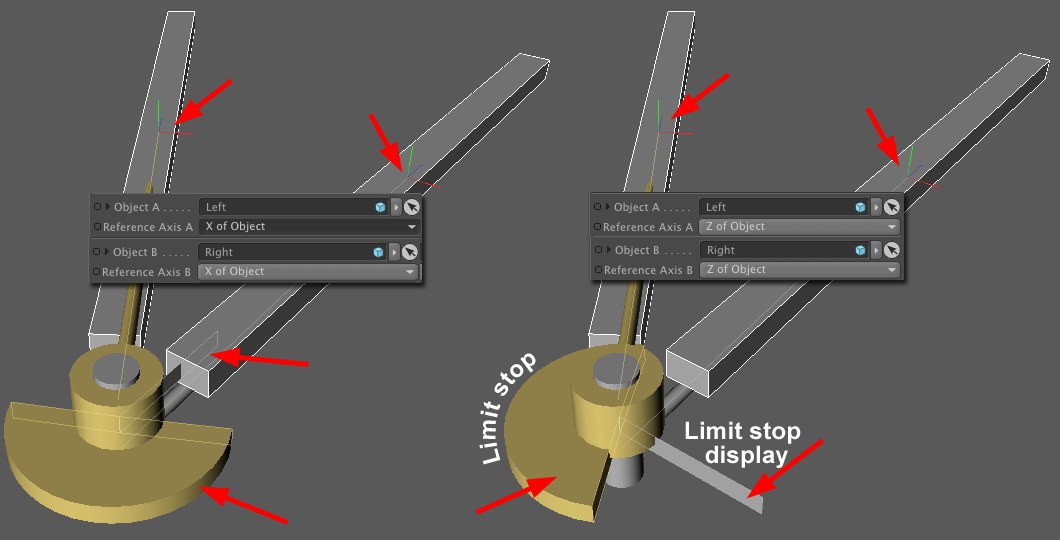
Take a good look at the image above. The rotational angle of both Connectors is restricted and have a limit stop and a limit stop display. Note how the limit stop display (belongs to Object B) aligns itself exactly parallel to the axis of Object B. The same is true for the limit stop.
You also see that selecting the Y of Object option would not make sense here because neither limit stop nor limit stop display could align themselves accordingly.
Let’s say the Connector lies exactly on the object axis of Object A. If Reference Axis A were set to Direction to Object the Connector would be very confused because the Connector and the object would be exactly the same. One of the object axes would have to be defined.
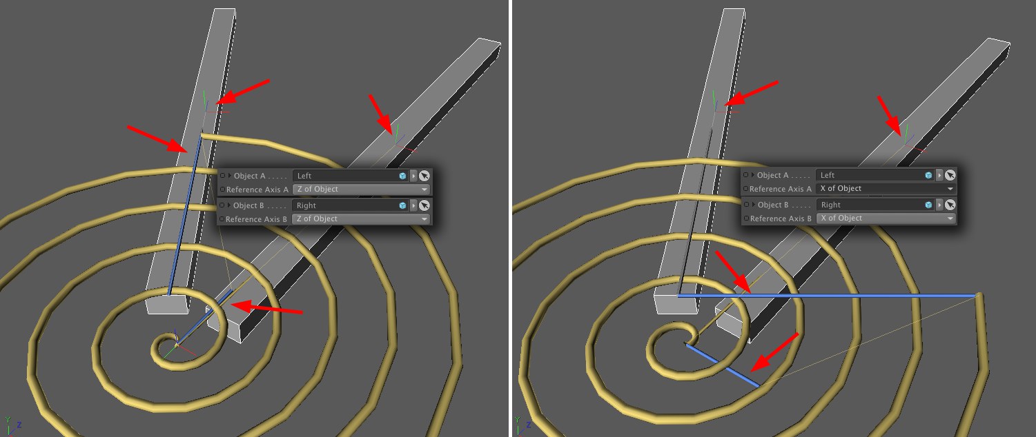
A torsion spring behaves similarly. Note how each blue spring "end" aligns itself to the defined axis, respectively. Selecting the X to Object option would not make sense in this case.
Many times you will not have to manually adjust the reference axes at all. This is necessary in such cases as described above in order to avoid Gimbal Lock. Imagine the Connector or spring are angled forward 90° in reference to the image above. This is where Gimbal Lock would occur. You can avoid this if you - as we suggested - align Connectors and torsion springs correctly in the Viewport (i.e. acording to their direction of rotation).
This might sound a little complicated but you can get a better grip on this by simply experimenting with the parameters. Just make sure you keep an eye on the limit stop and limit stop display when modifying parameter values:
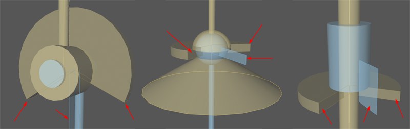 Limit stop and limit stop display for various Connectors.
 Index [-2147483648..2147483647]
Index [-2147483648..2147483647]
This is the object’s index number. Internally, all of a polygonal object’s points (including generated points) are numbered. This is displayed interactively in the Viewport when you browse the values.
All object points (however, only for polygonal objects) are listed in the Structure Manager.
You can drag a Point Selection tag or a Vertex Map into this field.
Region Of Influence [1..1000%]
Region Of Influence [1..1000%]
Since it is not that easy for Soft Bodies to process the effect of a force on a single object point (this often looks unrealistic), the Region of Influence parameter can be used to define a region around a point within which the effect of a force can be introduced. A value of 100% will include the entire mesh. In doing so, the polygon point (or polygon selection) itself will be weighted with 100% and the point most distant from it with 0%. When lesser values are used correspondingly fewer points will be affected by the force. A value of around 1% will only affect the selected point or selection (however, internally larger values will in fact be in effect as a result of a built-in protective mechanism).
A lesser value can be useful if you want to couple larger regions defined via point selection to Dynamics Connectors, Springs or Motors (e.g., a tubular Soft Body that is connected via a Connector to a circle).
Shape Conservation [0..+∞]
Shape Conservation [0..+∞]
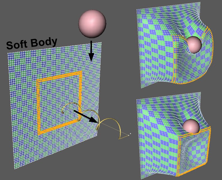 Highlighted point selection on a Soft Body is pulled by a spring whilst a sphere simultaneously falls onto it. Top right: low Shape Conservation value; bottom right: higher Shape Conservation value.
This value defines the degree to which the selection or point geometry affected by a vertex map can be deformed by a force. Lesser values result in greater deformations; increasing values result in correspondingly lesser deformations.
Damping [0..+∞%]
Damping [0..+∞%]
Returning an object to its original shape is done using springs, whose damping is adjusted using this value. Lower values increase the stiffness of the effect.
This option only affects collisions of objects that have been affiliated with each other by the Connector. When creating a scene and testing certain constructs it can be distracting to have collision detection enabled.
When the Type option is set to Ragdoll the movement can be restricted to a cone-shaped space. This setting lets you adjust the size of the open end of the cone.
Ellipse
Cone Radius Y [0.1..89.9°]
If the Ellipse option is enabled, the (perfect) cone can be pressed together, which is done using the Cone Radius Y value.
This and the following 4 parameters are only made available when Wheel Suspension option is selected in the Type menu.
Steering Angle defines the degree of steering lock around the Y axis of the Connector. You can animate this option to create realistic vehicle steering characteristics.
Suspension Rest Position [-∞..+∞m]
This value defines location of the rest position of the integrated spring based on the origin of the Connector. Negative values will push the vehicle up.
This value defines the amount of force needed to compress or expand the spring from its rest position. The harder the spring the more force that is needed to press it together or to stretch it (and the faster it rebounds).
As with a car’s suspension, this value is used to define the damping effect (i.e. like a "shock absorber"). This effect ensures that the stiffness of the spring is such that the tires always remain on the road. The greater the Suspension Dampening value the faster the wheels will come to rest.
If you used the Upper Limit Y or Lower Limit Y values to define angle limits, the Bounce parameter can be used to define how the movement rebounds when the object has reached the respective limit value.
Lower Limit X
From [-∞..+∞m]
Upper Limit X
To [-∞..+∞m]
Lower Limit Y
From [-∞..+∞m]
Upper Limit Y
To [-∞..+∞m]
Lower Limit Z
From [-∞..+∞m]
Upper Limit Z
To [-∞..+∞m]
For Connector types that allow movement, the movement can be limited to the respective axis from the Connector origin.
Angular Limit
Angular Limit 2
From [-∞..+∞°]
To [-∞..+∞°]
Breaking Force
Force [0..+∞m]
Breaking Torque
Torque [0..+∞]
Limits can be defined for the Force and Torque’s
Note that you must use very high values (up to six digits) depending on the Project and the specific effect. For example, a value of approx. 1000 must be entered to hold a Cube in place with the default Project Preference settings.
Higher values make the Connector more stable and smaller values will cause the Connector to break correspondingly easier.
Note the you can also let other types of Connectors break (or be, repaired’) using XPresso (Dynamics Connector State Node).
 Angle limits applied to various Connectors. The angular limit display (arrow of each example) can only move within the yellow Angular Limits.
An angular limit can be defined for almost all Connector types that allow rotation. Once all angular limits have been defined the objects can rotate any number of times around the center of the hinge (or along a slider). Note that the angular limits will only have an effect within the range of a SINGLE rotation.
The Connector type Cardan, which permits 2 rotational levels, can be further restricted via the Angular Limit 2 value.