Object Properties
Two types of Motors are available:
A linear force parallel to the Motor’s Z axis will be created.
A torque around the Motor’s Z axis will be created.
Both types are generated simultaneously.
Object fields A and B can be found in the following Dynamics objects:
- Connector
- Motor
- Spring
These 3 objects each connect 2 objects using different methods.
Both objects can be dragged into the Object A and Object B fields, respectively. If one of the Object fields is left empty, the following will result:
- Connectors: Position and rotation of the Connectors are fixed (otherwise the Connector would move/rotate with the objects).
- Motors: The basic principle "action = reaction" no longer applies. Force and torque are generated autonomously (see below).
- Springs: One of the springs will lie in the world coordinate system’s origin.
Except when using the Ragdoll and Wheel Suspension modes, it does not play a role in which order the objects to be connected are dragged into the Object A and Object B.
If an Object field is left empty when using Motor Dynamics: According to the laws of physics (actio=reaction), when one body exerts force on another, the second body exerts a collinear force on the first equal in magnitude but oppositely directed. This condition is met when each field contains an object. A good example is that of a helicopter: The rotor blades are driven by a motor and rotate accordingly. Simultaneously a colinear force is exerted on the helicopter’s fuselage. The tail rotor compensates for this - otherwise the fuselage would rotate around its vertical axis.
 An ascending Zeppelin is being held in place using a Connector with various restraining lines.
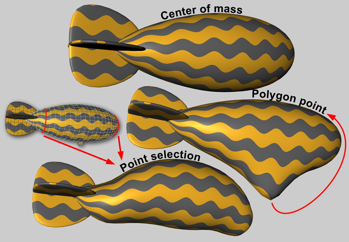
Wherever forces guide an object, the point on the object at which this occurs is important. For example, if a motor that pushes a Hard Body object along is located at that object’s center of mass, the object will be moved in a straight line (in the absence of any other forces). If the force affects the object outside of its center of mass, torque will automatically be generated and the object will rotate.
Soft Body objects, however, behave differently. Each object point is connected via springs to other points. If a force affects only a single point an unwanted result can be produced. However, the effect can be spread to larger regions:
The Attachment A and Attachment B parameters are available for the following Dynamics objects:
- Connectors
- Motors
- Springs
This option contains no additional settings. The force is generated at the center of the given object’s mass. No deformations will occur on Soft Body objects.
This option lets you select a specific object point at which the force will have its origin. The Region of Influence value lets you increase (or decrease) the region around this point within which the force will affect the object. This is only relevant for Soft Body objects and has no effect when applied to Rigid Body in conjunction with Connectors.
Force can also be applied via Maps (Point Selections tag oder Vertex-Maps). Additional parameters will be made available with which you can, for example, adjust the degree to which the selected (or weighted) points can be affected.
A Dynamics Motor with a Linear force or a Dynamics Spring can be given an offset, which defines (from the object origin) the point at which the force should take hold. If an offset is defined a torque will automatically be generated.
Index [-2147483648..2147483647]
Index [-2147483648..2147483647]
This is the object’s index number. Internally, all of a polygonal object’s points (including generated points) are numbered. This is displayed interactively in the Viewport when you browse the values.
All object points (however, only for polygonal objects) are listed in the Structure Manager.
You can drag a Point Selection tag or a Vertex Map into this field.
Region Of Influence [1..1000%]
Region Of Influence [1..1000%]
Since it is not that easy for Soft Bodies to process the effect of a force on a single object point (this often looks unrealistic), the Region of Influence parameter can be used to define a region around a point within which the effect of a force can be introduced. A value of 100% will include the entire mesh. In doing so, the polygon point (or polygon selection) itself will be weighted with 100% and the point most distant from it with 0%. When lesser values are used correspondingly fewer points will be affected by the force. A value of around 1% will only affect the selected point or selection (however, internally larger values will in fact be in effect as a result of a built-in protective mechanism).
A lesser value can be useful if you want to couple larger regions defined via point selection to Dynamics Connectors, Springs or Motors (e.g., a tubular Soft Body that is connected via a Connector to a circle).
Shape Conservation [0..+∞]
Shape Conservation [0..+∞]
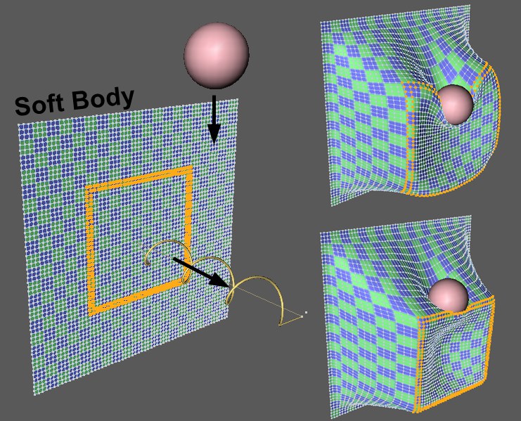 Highlighted point selection on a Soft Body is pulled by a spring whilst a sphere simultaneously falls onto it. Top right: low Shape Conservation value; bottom right: higher Shape Conservation value.
This value defines the degree to which the selection or point geometry affected by a vertex map can be deformed by a force. Lesser values result in greater deformations; increasing values result in correspondingly lesser deformations.
Damping [0..+∞%]
Damping [0..+∞%]
Returning an object to its original shape is done using springs, whose damping is adjusted using this value. Lower values increase the stiffness of the effect.
As mentioned in the description of Object A, "action = Reaction" applies for both objects. Use this setting if you want force or torque to affect one of the objects in a non-realistic manner.
The following modes are available:
Force or torque will be reduced in accordance wit the Linear Target Speed and Angular Target Speed values when the target speed has been reached. More force or torque will never be generated than is defined here.
Force or torque is applied without taking speed into consideration. This can result in speeds increasing immeasurably.
If Mode is set to Regulate Speed a maximum speed can be defined here. The force will then be limited internally when this defined speed is reached. The prefix defines the direction.
Exerts a linear force along the Motor’s Z axis. Depending on the object’s mass and friction (e.g., cube on a floor), higher values may be required.
Angular Target Speed [-∞..+∞°]
If Mode is set to Regulate Speed, a maximum angular speed can be defined here. The torque will be limited when this defined speed is reached. The prefix defines the direction of rotation.
Exerts torque around the Motor’s Z axis. The larger the object’s mass the greater the value needed.