CATIA V5 Import Settings
Note that many of the following options will only work if the respective export options in the CAD applications also export these elements. This applies to the Combine function in particular.
![]() General
General
If this option is enabled, the parts’ original scale defined in the file will be used (mostly millimeters). If this is not desired, simply disable this option and scale the file using the following Factor setting.
This factor can be found at numerous locations throughout Cinema 4D when importing or exporting foreign formats. Therefore, don’t be surprised if the term ,export’ is used if this factor is seen in an import function (this factor is explained as a whole here).
This factor lets you scale files upon import/export, i.e., practically all relevant numerical values saved in the file or those to be saved will be multiplied by this factor and then saved - or interpreted when loaded.
The unit at the right in turn defines how upon
- Import the numerical value saved in the file is converted to the current Cinema 4D unit. Example: if an X value of 1 is saved in the file and you define Feet, the X value will be converted to 30.48 cm in Cinema 4D (if centimeters are defined by default in Cinema 4D).
- Export numerical values are saved in the file. Example: an X value is set to 100 cm in Cinema 4D. If you define Feet for export, the exported file will save a numerical value of 3.281 (1 meter = 3.281 feet).
More information about units and scaling can be found in the Project Scale section.
A file elements that can be imported as geometry will be loaded if this option is enabled.
CAD files also contain splines. Enable this option if you want to import splines.
CAD files often contain countless numbers of identical objects (e.g., a machine with 1000 identical screws) as instances. If these instances should also be loaded in Cinema 4D as such, you can select from the following selection options (see also Instance Mode):
- None: All instances in the CAD file will be converted to regular objects
- Instance: All instances will be loaded as instances
- Render Instance: All instances will be loaded as memory-saving render instances (for more information on the differences, see link above). This is the recommended option.
CAD files have helper objects that define a point in space or a point with an orientation. These are designed to help orient objects (e.g., during construction) but are of no use in Cinema 4D. Disabling this option will omit them from import. Otherwise they will be imported as Null objects.
If hidden objects are defined in the CAD file, enabling this option will display these in the Object Manager with the suffix _hidden. If this option is disabled, such objects will not be imported.
![]() Optional
Optional
Use this setting to define if and how Normals should be imported.
You have the following options:
- None: no Normals saved in the CAD file will be assumed, which can often result in faulty shading
- Normal tag: the Normals saved in the CAD file will be assumed within a Normal tag. This produces the best results.
- Phong Tag Edge Breaks: using this option will convert existing Normals to a Phong tag with broken Phong edges and a Normal tag will be created. The original Phong angle cannot be restored but the geometry contains approximately the original shading and is therefore completely modifiable (which is not necessarily the case with the Normal tag).
Each object in Cinema 4D can have a color without having a material. These colors can be accessed in the Basic tab: Display Color. Each imported object can be assigned a color using this selection menu:
- None: no color will be assigned.
- Original: the colors assigned in the CAD file will be used.
- Random: random colors will be assigned.
If you prefer to assign colors using a material, this can be done using the Material menu below.
Here you can define how the layers in the CAD file or those created by Cinema 4D will be handled.
You have the following options:
- None: no layers will be assigned.
- Original: if the elements in the CAD file are organized in layers, these can be assumed in Cinema 4D. Random layer colors will be generated (see also Layer Manager and Layer Concept). If the file contains no layers, all elements will be placed on the same layer.
- Scale-Based Tessellation: if this option is enabled, the objects will be separated into 3 groups based on their scale. The objects will be assigned to one of the scale group layers. Note that no instances will be assigned to these layers since instances can refer to different objects with different tessellations.
If you want to assign a material to the imported objects, this can be done here.
You have the following options:
- None: no materials will be imported.
- Original: if the CAD file contains materials, these will be converted to Cinema 4D materials (primarily, the diffuse color and specular will be assumed) and assigned to the respective objects.
- Based on Display Colors: if display colors (not materials) are assigned in the CAD file, these will be imported as materials and assigned, if necessary with the help of polygon selections. The colors’ RGB values will be assigned as material names.
- Original with Random Color: If the CAD file contains materials, Cinema 4D materials with a random color will be created and assigned to the respective objects.
If the CAD file contains UV files, these can be assumed in Cinema 4D via UVW tags. However, these will most often be of poor quality, which means that they will have to be edited accordingly.
Similar to Cinema 4D, elements in CAD files can be hidden. If this property is assigned in the file and this option is enabled, Cinema 4D will assume the object’s visibility using its own switches (visible in Viewport/ for rendering) in the Object Manager.
![]() Modifications
Modifications
These settings can be used to define how CAD elements in Cinema 4D should be structures. It’s generally not very useful if 2,000 CAD entities (that may comprise only a single object) are imported as 2,000 objects into Cinema 4D. Here you can select from different criteria for combining these objects. You can, for example, combine surfaces to objects or all objects that lie on the same layer can be arranged to a single object. You can test the various options to see what works best for your purposes.
The following options are available:
- None: no combining will take place and individual surfaces will be imported as objects. This mode is the least advantageous of them all.
- Original Bodies: an attempt will be made to combine several surfaces in order to create a coherent mesh.
- By Topology: an attempt will be made to combine all surfaces that belong to the same volume (this is the mode that is most recommended).
- By Color: all surfaces of the same color will be combined into a single object.
- By Layer: all surfaces belonging to the same layer will be combined.
Note that combining - in particular with larger models - after they are loaded can take quite some time to complete.
This setting does not work in conjunction with splines.
Enable this option if objects are rotated by 90° when imported (compared to the CAD software). The table you imported will then stand on its legs and not on its side …
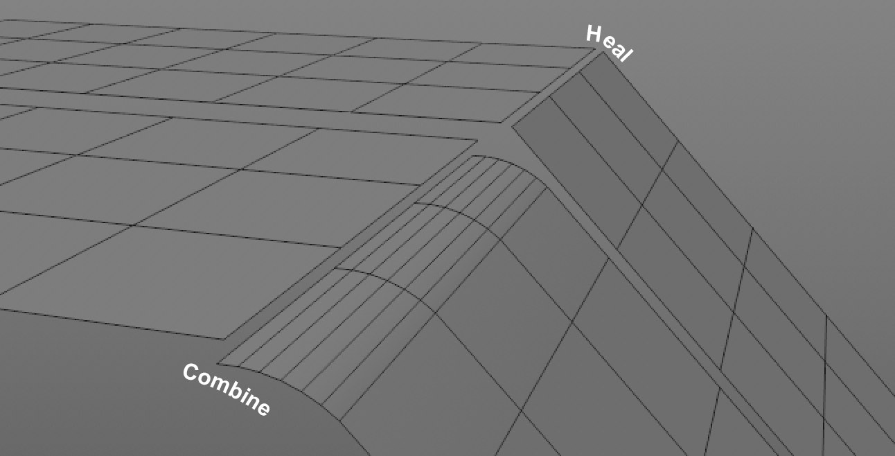 Such (NURBS) faults can be eliminated by using Heal and Stitch.
When constructing and exchanging CAD files between systems and programs, imprecisions and minor faults can occur in the geometry, e.g., tiny gaps on surfaces that are actually closed, points that don’t lie exactly on top of one another, etc. The result would be a mesh that is not watertight. This is what the Heal and Stitch functions aim to prevent.
Heal can remove gaps between surfaces whose edges should meet. If Heal doesn’t do the trick you can also add Stitch to the equation.
Stitch attempts to close gaps between surfaces even if they don’t overlap (e.g., slightly parallel offset edges). Points will be moved in the process, i.e., the surface geometry will be modified.
Use this setting if Heal doesn’t produce the desired result.
The value entered here refers to the number of (internal) repetitions of the function. Larger values can close larger gaps.
A value of 0 will disable the Stitch function.
Enable this option to omit hierarchies that are unecessary for Cinema 4D and would only be imported as Null objects.
![]() Tessellation
Tessellation
Scale Based Tessellation
Scale Range
A CAD file contains tiny objects as well as a huge structure, which are all essential for the project. In a visualization, tiny objects like nuts and bolts don’t play a major role and don’t need to be imported with the same resolution as the larger objects.
Scale-Based Tessellation can be used to arrange objects in 3 scale categories for separate tessellation (described above):
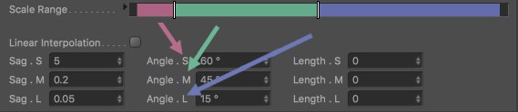
The bounding box sizes (more precisely: the largest diagonal) are ascertained for the objects to be imported and grouped relative to the largest bounding box. Percent values will be produced that are shown in color in the image above with increasing values from 0% to 100% from left to right. The sliders can be moved as desired. The selected slider’s value will be displayed if you click on the small arrow to the right of Scale Range.
This option belongs to the Scale-Based Tessellation settings. If enabled, it will disable the middle range and interpolation will only take place between minimum (S) and maximum (L).
Sag . S [0..999999]
Sag . M [0..999999]
Sag . L [0..999999]
Defines the Distance (see below) for the 3 large regions.
Angle . S [0..180°]
Angle . M [0..180°]
Angle . L [0..180°]
Defines the Angle (see below) for the 3 large regions.
Length . S [0..999999]
Length . M [0..999999]
Length . L [0..999999]
Defines the Length (see below) for the 3 large regions.
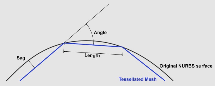
When importing a NURBS surface, these three-sided polygons have to be reproduced. This process is called tessellation.
The Detailing settings can be used to define how precisely the polygon mesh that is generated should follow the NURBS surfaces.
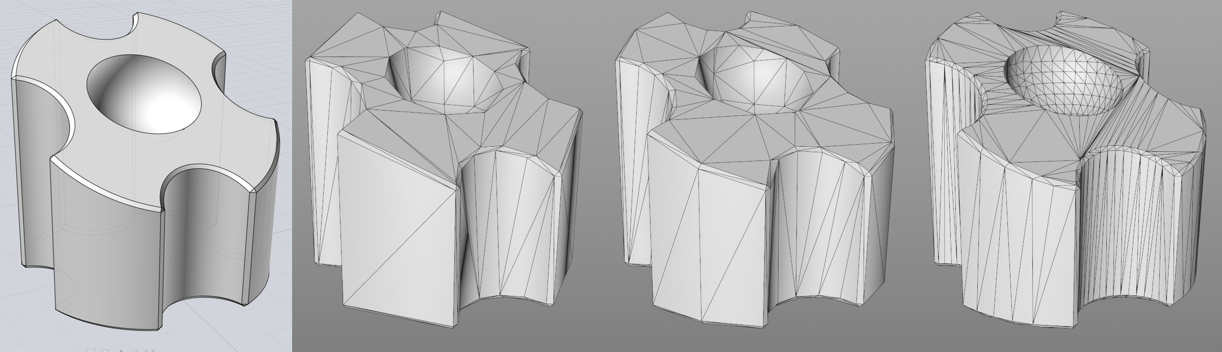
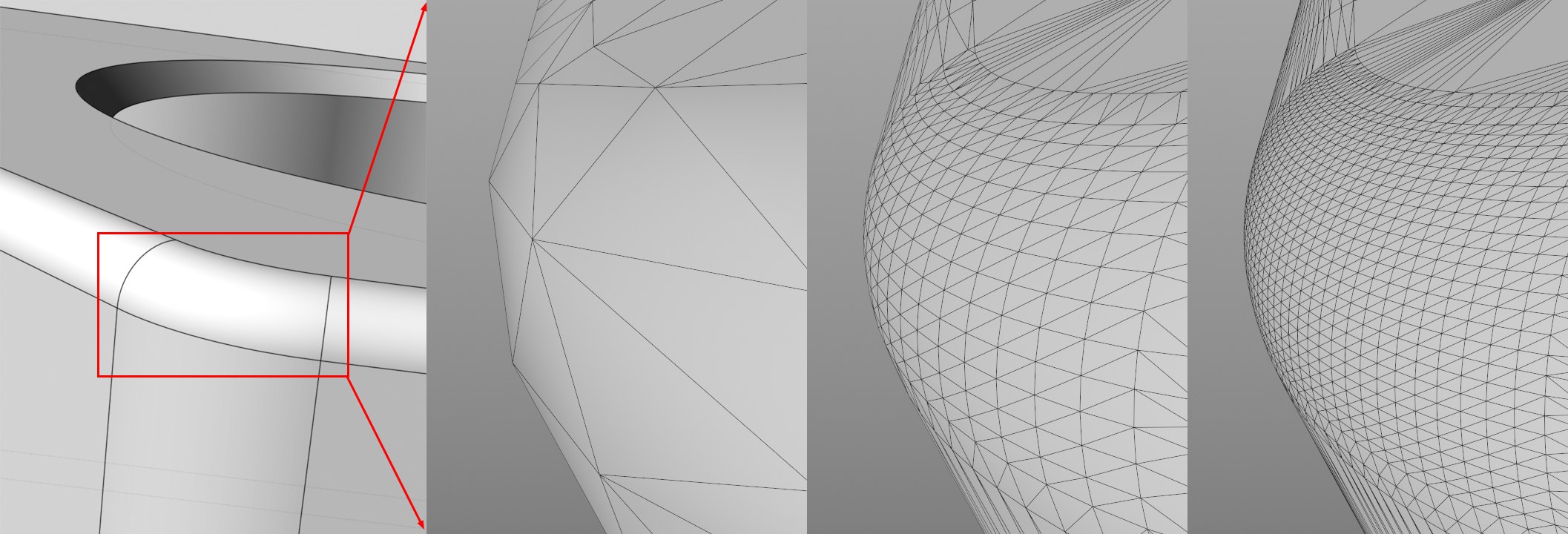 The NURBS surface on the left after Tessellation with Detailing set to Low, Middle and High, respectively.
Detailing offers the following options:
- Original: the tessellation values saved in the CAD file will be used.
- Custom: will automatically be used if you manually enter values.
- High, Medium, Low: applies the respective quality level to the Max Sag and Max Angle settings (click on the small arrow to display these settings).
Note that the tessellation process takes into account all 3 defined maximum values for Max Length (mm), Max Angle and Max Sag (mm). The maximum resolution will be calculated within these limits. Generally speaking, the smaller the values, the higher the resolution. If 0 is defined, the respective criteria will be ignored.
 Depending on the settings defined, the polygon mesh will follow the curvature more or less precisely.
 The original NURBS on the left; declining Max Sag (mm) values from left to right (other criteria disabled).
This value defines the maximum distance the polygon surface can have from the NURBS curve. Define smaller values for correspondingly higher polygon mesh resolutions.
 The original NURBS on the left; declining Max Angle values from left to right (other criteria disabled).
Max Angle defines the maximum angle between adjacent polygon surfaces that cannot by exceeded (see image for Max Sag (mm).
 Left: Original NURBS; from left to right sinking values for Length Max (mm) (other criteria disabled).
Length Max. (mm) defeines a triangle’s maximum side length. Lower values make it possible to avoid the often problematic, very long triangles. But be careful: values that are too low will generate an unnecessarily high number of triangles.