Object Properties
Internally, the MoText Object uses the Extrude object to make it three dimensional. Use the Depth setting to define the extend of the text’s 3D depth.
Use this setting to define the subdivision of the extruded text elements. In most cases, a value of 1 will suffice. Only if you want to deform the text elements further, e.g., bend them, should Subdivision be set higher.
Enter the text into the Text box. You can enter up to multiple lines of text — press Return to start a new line. The text appears in the viewport as a spline primitive when click outside the text box.
TrueType, OpenType and PostscriptFonts can all be used in Cinema 4D. However the following restrictions do apply:
- Macintosh (with an operating system prior to macOS X 10.5): OpenType fonts will only work if they contain TrueType applications. All characters within an installed font can be used (Euro characters, Japanese characters, etc.)
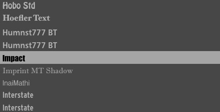
The font preview in the selection menu makes it easy to select the right font. You can also scroll up and down the list using the arrow keys or scroll wheel.
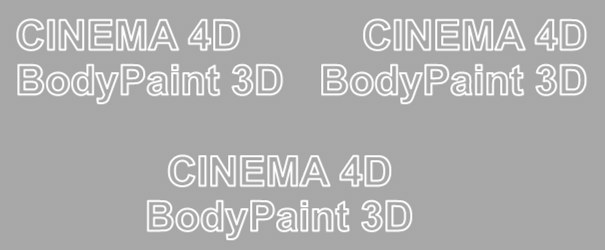
Set the text’s alignment to left-aligned, centered or right-aligned.
The following 3 parameters apply to the complete text whereby the Kerning settings affect individual letters and are used additively to these parameters.
The height of the letters, in world coordinates.
With these command you can insert space between the characters.
With these command you can insert space between the text lines.

Some fonts are poorly designed and will have noticeable overlapping edges. Cinema 4D cannot improve these faults. Always use high quality fonts for best results.
You can get a good result with 3D fonts by using the Bevel command on a font object and restricting the angle limit to approx. 20°.

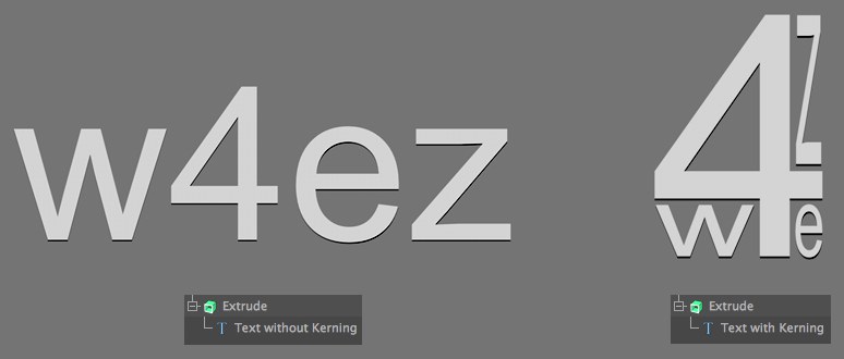
The Kerning settings let you define text size and spacing per letter. This should eliminate the need for external programs for making parametric modifications to text, e.g., if you want to adjust the spacing between the letters "A” and "V” (which is quite common). All modifications can be made interactively in the Viewport.
The following properties can be modified for a given letter (or for an entire text):
- Distance from previous letter
- Horizontal or vertical size, or overall scale
- Baseline Shift (vertical position)
In the end you can come up with parametric creations like the one on the right:
Enabling the Show 3D GUI option will display the following handles in the Viewport:
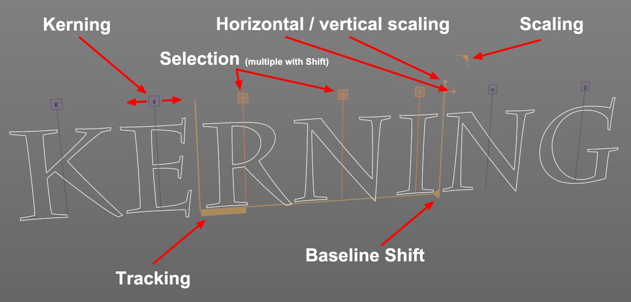 Any of the marked handles can be selected and dragged with the mouse.
Above each letter you will see a correspondingly marked square handle, which can be dragged (without Selection) to adjust the spacing to the left of the letter. Of course a Selection can also be used:
- Click on a letter handle to select it
-
Shift + click on a handle will additionally select all letters between this letter and the last selected letter (or deselect if you clicked on the wrong letter). The properties of the selected letters (Tracking, Scale and Baseline Shift) can then be modified simultaneously (each to the same absolute value) when one of the handles marked in the image above is moved.
Letter selections can be made independent of the text itself and affect only those letters, i.e., if you select letters 5-9 and enter a different text, only letters 5-9 will be affected.
Dragging a handle – and pressing the following keys - will have the following effect:
-
Shift : Corresponding parameters will be modified in steps of 10. -
Ctrl/Cmd : Corresponding parameters will be modified interactively and very slowly (which makes fine-tuning easier; if theShift key is pressed simultaneously, parameters will be modified in steps of 1).
Use this option to define whether or not the interactive 3D handles should be displayed in the Viewport. This option should be disabled as soon as you have finished fine-tuning the kerning of the text to avoid inadvertently modifying text properties at a later point.
The following parameters can also be adjusted interactively in the Viewport by using the corresponding handles (see above).
These settings are numeric selections that you can normally define interactively in the Viewport (see above). However, it can be easier to modify these values in the Attribute Manager if, for example, the letter handles overlap. If you want to select the 2nd letter, enter 1 for Start and 2 for End. To select letters 3 to 6, enter 2 and 6, respectively.
These settings can be used to successively access all individual letters and their kerning parameters using and Iteration XPresso node.
Both settings basically have the same function in Cinema 4D with the exception that Tracking can be modified at any time in the Viewport without making a selection using the handles positioned above each letter. The Kerning setting – which is displayed as a single handle when multiple letters are selected – can be applied to multiple letters simultaneously.
Both settings are used to adjust the spacing to the left of each letter.
Use these settings to individually adjust letters’ horizontal and vertical scale.
This value defines the overall scaling of letters (taking the aforementioned values into consideration).
Use this setting to shift the position of letters up or down.
Clicking this button will set all values back to their default values.
Clicking this button will reset the values of all selected letters back to their default values.
Clicking this button will select all letters in the Attribute Manager’s Text field.
Note that the Kerning settings cannot be animated via normal keyframes for internal reasons. Animations can be done via XPresso where all Kerning settings can be accessed. Use the following Project as a reference:

Here you can define how the spline is further subdivided with intermediate points. This affects the number of subdivisions created when using the spline with Generator objects. Even after you select the Interpolation type from the menu for the Intermediate Points, you can still make changes.
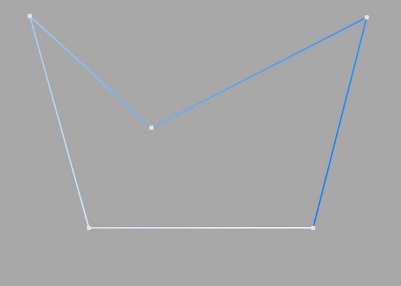
This method of interpolation locates points only at the vertices of a spline, using no additional intermediate points. You cannot enter values into the Number or Angle boxes. For B-splines, the vertices, and therefore points, might not be located on the spline curve.
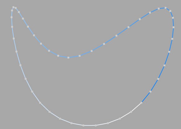
This interpolation type first locates points at spline vertices. In the case of B-splines, points are located at positions on the spline curve closest to the spline vertices. Number (N) corresponds to the number of intermediate points between vertices. The points are positioned closer together on areas of the spline with more curvature.
You cannot enter values into the Angle box. The interpolation is not affected by reversing the point order.
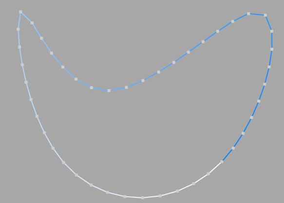
This interpolation subdivides the spline so that the distance between any two consecutive points, as measured along the spline curvature, is constant. One point is always located at the beginning vertex. For open splines, a point is also located at the ending vertex. Other points generally do not coincide with vertices.
You cannot enter values into the Angle box. The interpolation is not affected by reversing the point order.
Open spline: ((Number + 1) * (number of vertices - 1)) + 1
Closed spline: (Number +1) * number of vertices
So an open spline with four vertices and a number of 2 will contain ((2+1)*(4-1))+1=10 intermediate points. If the spline is then closed, a further (virtual) vertex is added — the number of intermediate points will then be (2+1)*4=12. This ensures that a spline is not more roughly divided when you close it.
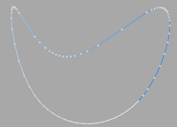
This interpolation type sets intermediate points whenever the angle deviation of the curve is larger than the value given in Angle. The points of the resulting curve pass through the vertices. If a spline has several segments, then the value of Angle will apply to each segment.
The Adaptive method gives the best results in rendering, hence it is the default interpolation method.
You cannot enter values into the Number box.
Subdivided is similar to Adaptive. Additional intermediate points will be added until the intermediate segments are shorter than the defined Maximum Length, i.e., the point intervals will not necessarily be equal to the maximum length. Lower values will result in higher quality, along with the disadvantages of working with a high number of points - slower refresh times in the editor view, etc.
Especially the render quality of deformed text can be greatly improved using this method. More or less perfect caps and edges without shading errors can be achieved by setting Maximum Length to the same value as Width in the Extrude object (Caps tab, activated Regular Grid option). The subdivision of the letters and caps will match and must not be done manually.
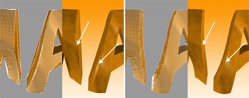 Left: Intermediate points Adaptive; right: Subdivided, applied to an active formula deformation object. Note the defined edges at the right of the image.
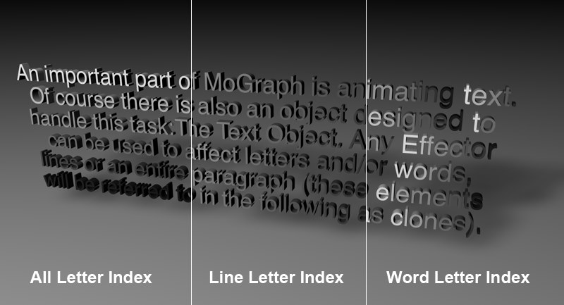 From left to right: All Letter Index; Line Letter Index; All Letter Index with a color shader whose Channel setting has been set to Index Ratio.
Each letter of the MoText Object is numbered internally. Depending on which Shader Indexing option is selected, the letters of the MoText Object will be numbered consecutively (All Letter Index), or the numbering will start again at 0 for each line (Line Letter Index) or word (Word Letter Index). So, what is this good for? Well, a color shader (see your Cinema 4D reference manual) with an Index Ratio channel setting uses this numbering for orientation. Furthermore, the internal U-coordinates also orient themselves according to this numbering scheme. The U-coordinates, which always have a range of 0 to 1, will be assigned to the letters as follows:
From the first letter of the text to the last.
Per line.
Per Word