Calibrate
This is where you will find the most important settings for the Camera Calibrator tag. This is where you interactively create lines and grids that you position on your reference image. This is also where you receive feedback regarding the precision of the lines and the possible results. A brief introduction about how to position lines can be found here.
Lines will be added in the Viewport whose end points can be repositioned. Lines can be selected (properties that can be adjusted will be displayed as colored elements in the Calibrate tab’s menu). Selected lines can be deleted (
Each time you
If the tag is already aware of a vanishing point direction, lines that are positioned interactively will automatically be assigned the known vanishing point direction as long as they lie within a certain tolerance. These will then be displayed in a dark color and labeled, Auto’ in the Calibrate tab’s Selection menu.
Click on this button to add a new line (existing lines can be duplicated via
Click on this button to delete a selected line (a selected line can also be deleted by pressing the
A grid is nothing more than two connected lines (each lies parallel to a different axis) that in reality run vertically to one another. A well-placed grid (that is placed along surfaces such as windows, facades, etc.) can be enough to calibrate a camera to the correct position.
The four grid points can be positioned individually. Grids can be selected on their outer edges (several adjustable properties are also displayed in the Calibrate tab. Selected grids can be deleted (
Each time you
Click on this button to add a new grid (alternatively, an existing grid can be duplicated by via
Click on this button to delete a selected grid (a selected grid can also be deleted by pressing the
A Pin is displayed in the form of a small orange circle in the Viewport. It can be moved with the cursor and will lock to line and grid points.
What is a Pin? Camera focal length and orientation can be defined using vanishing points but the exact position of the camera within the scene (incl. the definition of scale) can only be achieved if fixed points exist both in the reference image (locked onto a defined line or grid point with a corresponding length) and within the Cinema 4D Project itself (that can be defined in the Coordinates settings; this is by default the world origin). This is what the Pin does.
Without Pins you would have to position 3D objects you want rendered as part of an image manually until they are positioned correctly. With Pins you can, for example, Flabio can be scaled perfectly according to his actual height of 1.98 m.
Click on this button to add a Pin (only one Pin per Camera Calibrator tag can be added).
Click on this button to delete a Pin.
In the Viewport you can interactively select Camera Calibrator tag elements. Several elements linked to the elements and selections will be displayed:
The information displayed shows if the selected line has been assigned to a vanishing point axis (e.g., for manual assignment, X OK’ or automatic assignment, X (Auto) OK). Lines not assigned will be marked, (Auto) XXXX.
Enable the corresponding option and enter a value, if known (this is the only way a camera position can be clearly defined in conjunction with a locked Pin). The line will then be marked at its ends by 2 perpendicular strokes in the Viewport.
Otherwise a line length calculated by the tag itself can be displayed here.
Known vanishing points will be displayed here.
Enable the corresponding option if you know the length of a given edge and enter the edge’s length (this is the only way a camera position and be clearly defined in conjunction with a Pin locked on the corner of a grid). Lines with known lengths will be marked at their ends by 2 perpendicular strokes in the Viewport.
If you know the grid’s aspect ratio, this value can be entered into the corresponding field. In most cases this will not be necessary, but when working with special calibrations (e.g., if one of the vanishing points lies an infinite distance away), entering the correct aspect ratio can be very useful and might also be the only way to reconstruct the correct angle and aperture (it can suffice to enter an approximate value).
If this option is not enabled the aspect ratio will be calculated automatically.
Normally, the Pin represents the world origin, which is why it is placed at 0,0,0 by default. A Pin can, however, be positioned anywhere in the scene using the coordinate values. Details about Pins can be found above.
![]() Display Settings
Display Settings
Axis
Axis
Offset
Offset
Segments
Segments
By clicking on the small arrow to the left of Display Settings, a menu will open with whose settings you can modify the appearance of the grid. You can change the number of lines (Segments) and the arrangement of lines (Offset) per axis.
The purpose of camera calibration is to reconstruct the camera position and aperture, i.e., both of the color fields marked above must be green. Lines or grids have to be positioned on the reference image until these two fields turn green (however, there are instances in which this can’t work - see Limitations.
In the examples below are some examples of how lines and grids can be positioned (of course it helps if posters and other elements are hung perfectly vertically; corners of rooms or door frames are better reference objects).
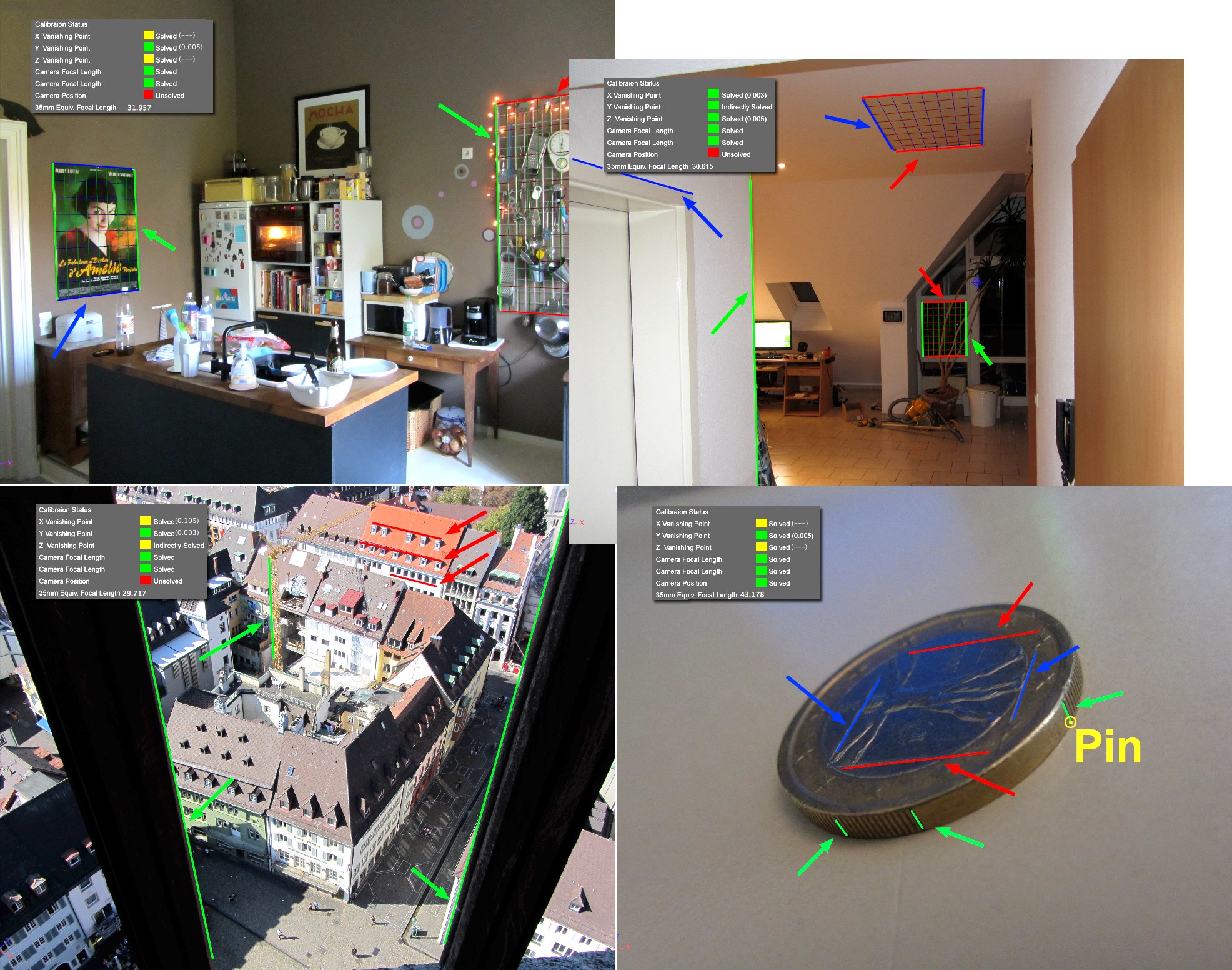 Various reference images, including lines and grids for camera calibration. Green lines lie parallels to the Y axis, red lines parallel to the X axis and blue parallel to the Z axis (
Calibration Status and color-coded display
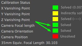
The color-coded display for reconstructed elements consists of three colors:
- Red: No solution found
- Yellow: Indirect solution found - large discrepancies possible
- Green: Solution with good accuracy found If the calculation does not have to be 100% accurate, yellow (indirect solution) can be acceptable. 3D elements placed over the reference image will look convincingly enough even with minor inaccuracies with regard to perspective and aperture when the scene is rendered.
If a high degree of accuracy is required you should make sure all color fields are green. Particularly when working with natural settings or organic shapes it can be difficult or impossible to locate perpendicular shapes for positioning lines or grids. This is where you have to use your best judgment when setting up your camera calibration.
At the right of each color field is a comment regarding an element’s definition, i.e., whether its definition was successful (Solved) or not (Unsolved). Additional comments / information are explained below:
X Vanishing Point
Y Vanishing Point
Z Vanishing Point
To calibrate a camera, at least 2 axes that lie on 2 parallel lines within the (real-world) reference image must be marked (the line pairs must, of course, lie perpendicular to each other). The vanishing point for the third axis can be determined automatically from the first two. For a higher degree of accuracy, the lines of the third axis should also be defined, if possible (which can be difficult, depending on the reference image).
The following comments can appear next to the color-coded fields:
- Unsolved (Insufficient lines): Additional lines should be positioned for the given axis.
- Unsolved (Inconsistent lines): Lines are marked incorrectly
- Solved (---): The corresponding vanishing point could not be ascertained. A static error calculation (value in parentheses) is not possible with 2 lines.
- Solved (e.g., 0.01): For at least 2 lines per axis the vanishing point cannot be ascertained using a static error calculation. The smaller this value is, the more precisely the vanishing point was calculated.
Note: Don’t only position lines to achieve a very low error value. Position lines to best match the elements in the reference image (otherwise you might end up achieving a low error value but you won’t have the best possible position for the camera).
Camera Focal length
Camera Orientation
Focal length and orientation can be calculated when all three vanishing points are marked as solved.
The exact camera position can only be calculated if a Pin (see below) is added and locked onto a line endpoint or grid corner point AND a line length or grid side length is numerically defined (e.g., Known Length X).
The following comments can appear next to the color-coded fields:
- Unsolved: The camera’s position has not been defined (a Pin must be added).
- Solved: Assumed distance. The Pin was not locked onto a line end point or grid corner or a numeric length value has not been entered. In this state, the camera can still be moved in the direction of view (no reference point for size ratio has been defined within the Project).
- Solved: The camera position has been defined (the Pin with is at its default world coordinates of 0,0,0). The camera can no longer be moved.
35mm Equiv. Focal Length is a common term to describe focal length (which is also dependent on the aperture size).
Projecting the reference image for rendering
After the camera has been calibrated (i.e., at least Camera Orientation and Camera Focal Length color fields are green), 3D objects can be added to the scene.
Objects that serve as dummy objects for other objects in the reference image have to be added, e.g., a floor or furnishings – of which the former can serve as shadow catcher and the latter as objects behind which a 3D character can walk, etc. This is what the Create Camera Mapping Tag function is for. The reference image must be visible in the empty regions when the scene is rendered. This is what the Create Background Object function is for.
The squash playing monster we introduced earlier would then appear like this in the scene:
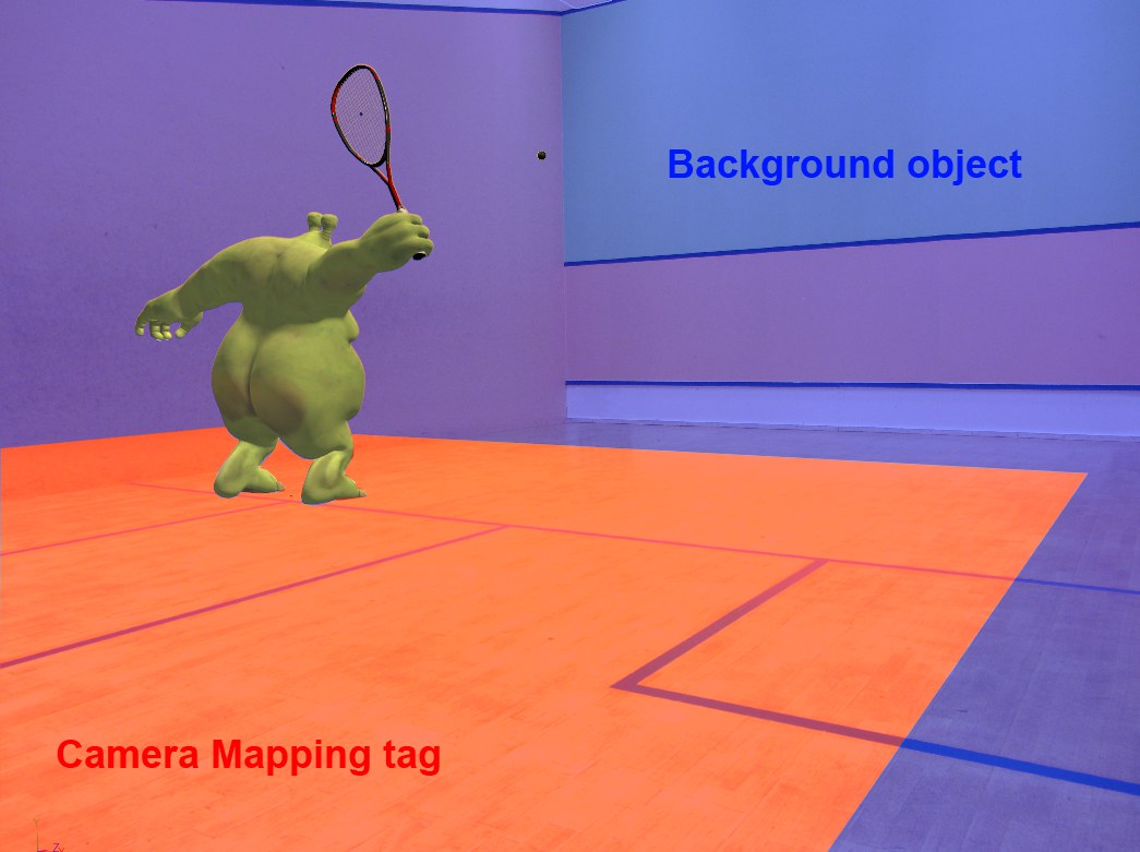 The 3D monster is standing on a Plane (Create Camera Mapping Tag) and the background object (Create Background Object) is visible in the empty regions.
Of course the camera with the Camera Calibrator tag should be used for rendering (enable the Use as Render View option for that Viewport).
The following will happen when you click on the Create Camera Mapping Tag button:
- A Material tag will be created (a corresponding material will also be created with the reference image in the Luminance channel) that will be assigned to the camera.
- This tag will project the reference image in the Projection Camera Mapping parameter.
- This tag can now be assigned to specific objects in the Project (simply drag it from the camera onto a given object). The reference image will then be projected onto these objects making the illusion perfect.
Clicking on this button will generate a Background object with the reference image projected onto it (the corresponding Texture tat and material will also be generated). Empty regions (i.e., where no objects have been placed) will also be filled when the Project is rendered.