Contour
Overview
|

|
|
|
| by Theo Daley | Robot model by Ian Robinson | by Saul Espinosa, model from Arctec3d.com | Models from polyhaven.com |
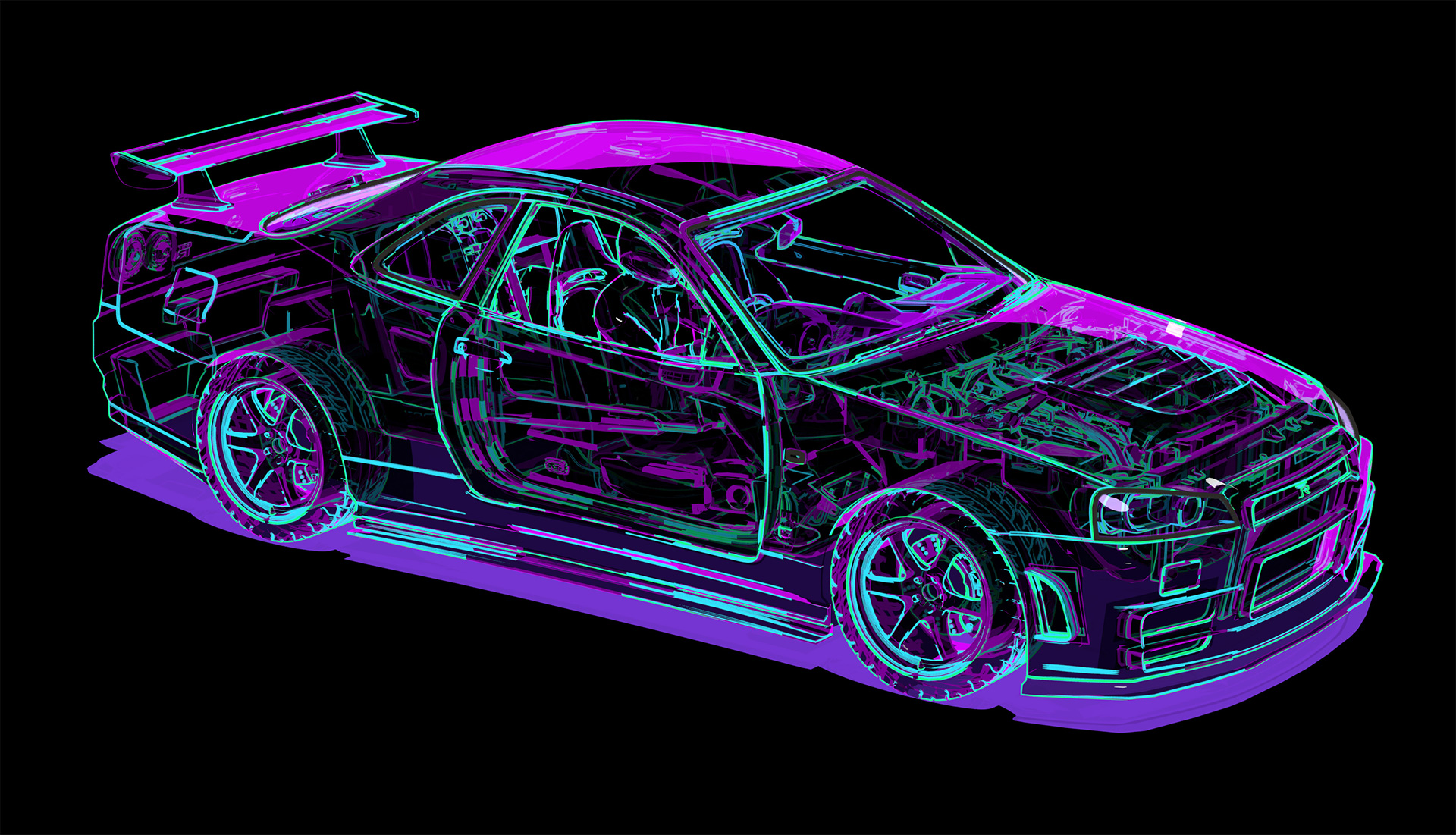
The Contour shader draws lines around an object's silhouette and along prominent internal edges that define an objects shape. Redshift's line drawing is shading based so it works automatically with reflections, refractions, depth of field, and motion blur but it is confined to the inner bounds of an object. Technically, a contour can never render outside of an object's silhouette but a workaround can be used to achieve a similar visual effect as described in the Contour Behavior section below, Breaking Boundaries.
The Contour shader is one of three shaders that make up Redshift's core offering of non-photorealistic tools. The Toon Material is used as the primary shading element to create stylized cel shaded looks, the Contour shader is used to create outlines around your objects, and the Tonemap Pattern texture adds a screen space pattern to your shading to mimic a halftone dot effect and others.
Contour works with all Surface shaders, like the Standard Material, and is not restricted to the Toon Material.
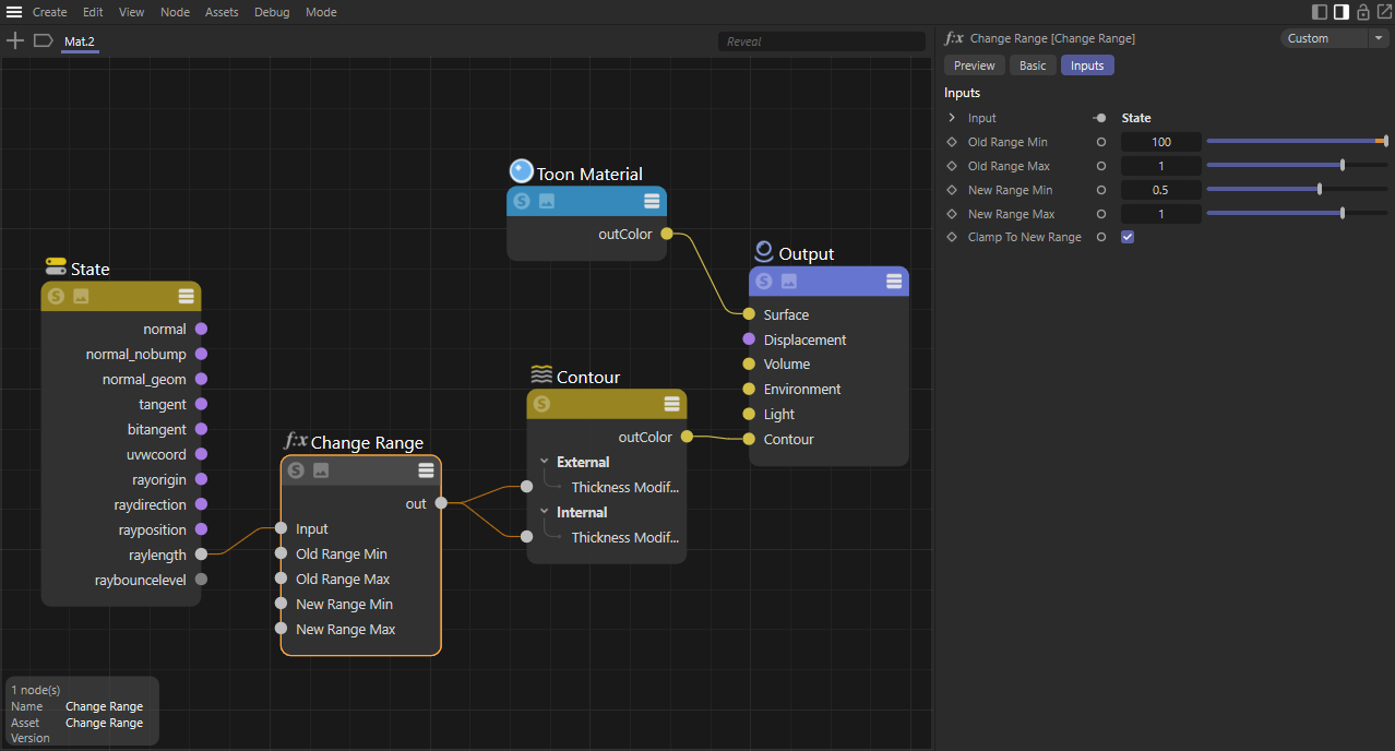
Example Graph
Basic Setup
The Contour shader requires a direct connection to the "Contour" port of the Material Output. Connecting it elsewhere is unsupported.

|
Thickness based on distance

|
| Contour thickness shrink |
To shrink contours as they fade into the distance a State node can be used. Create a State node and use the ray length output into a
|
Contour Behavior
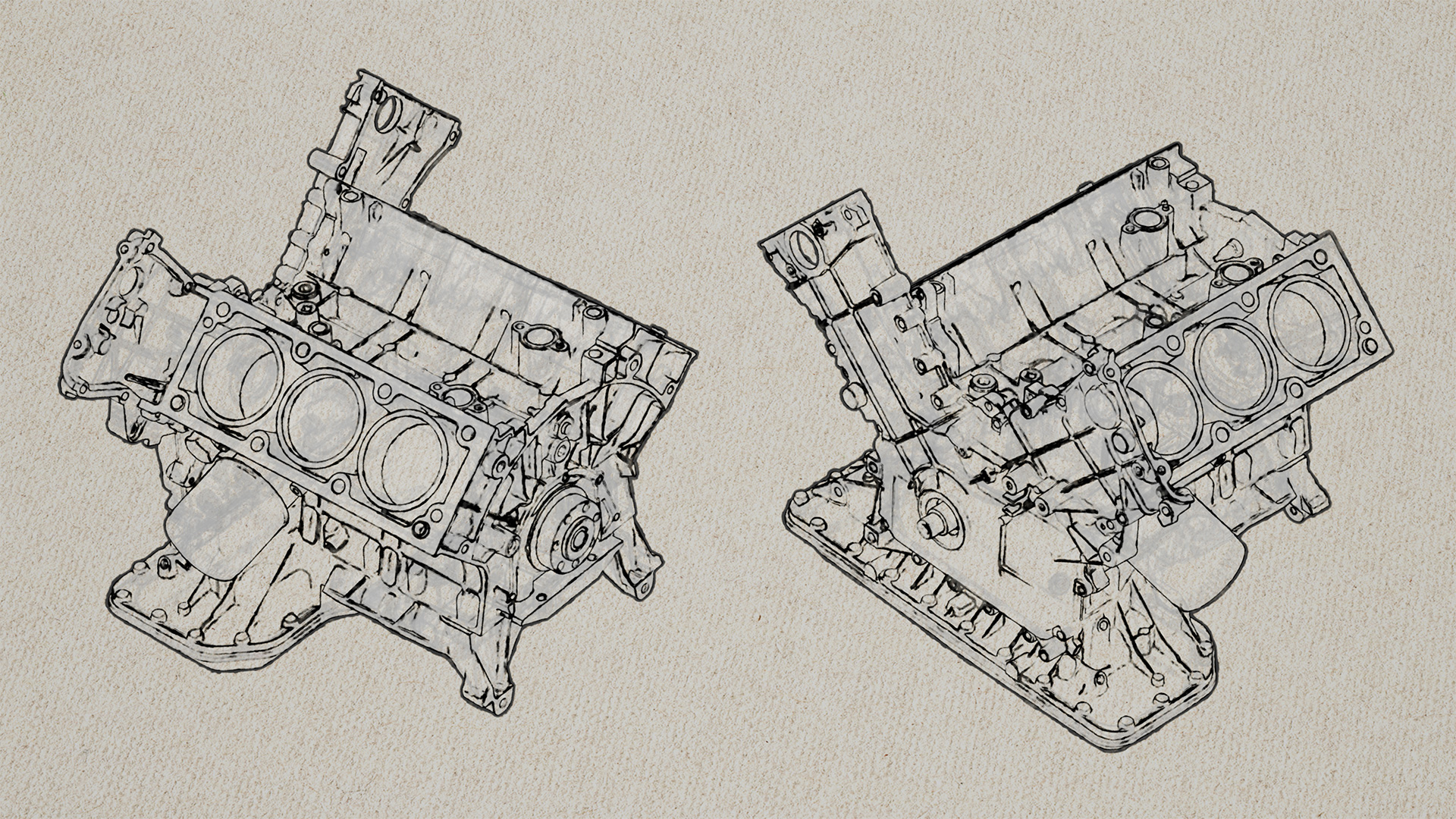
External vs Internal Lines
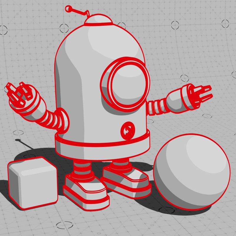
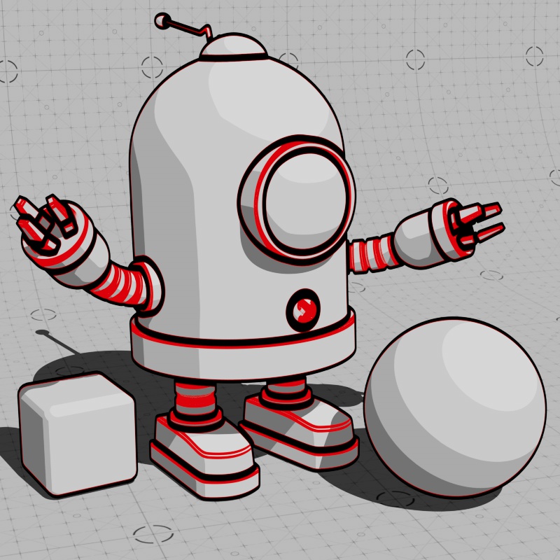
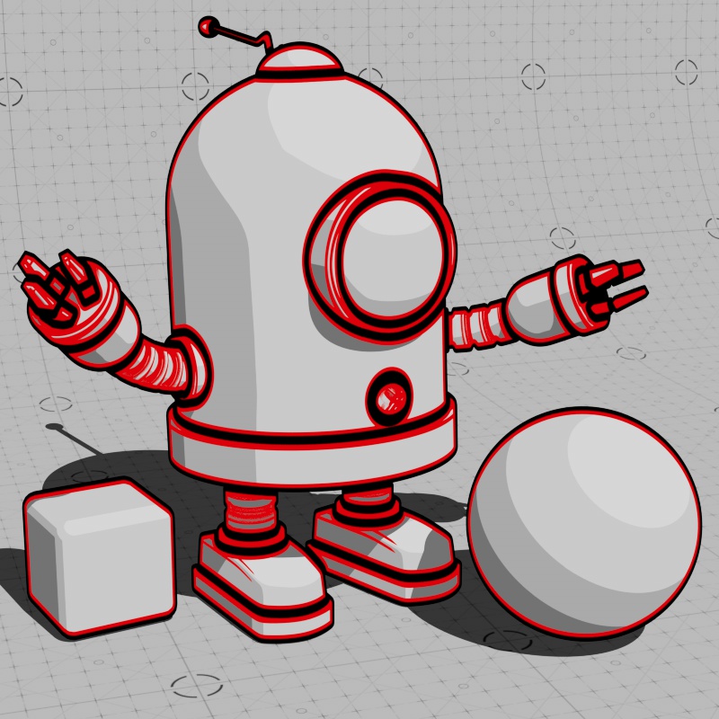
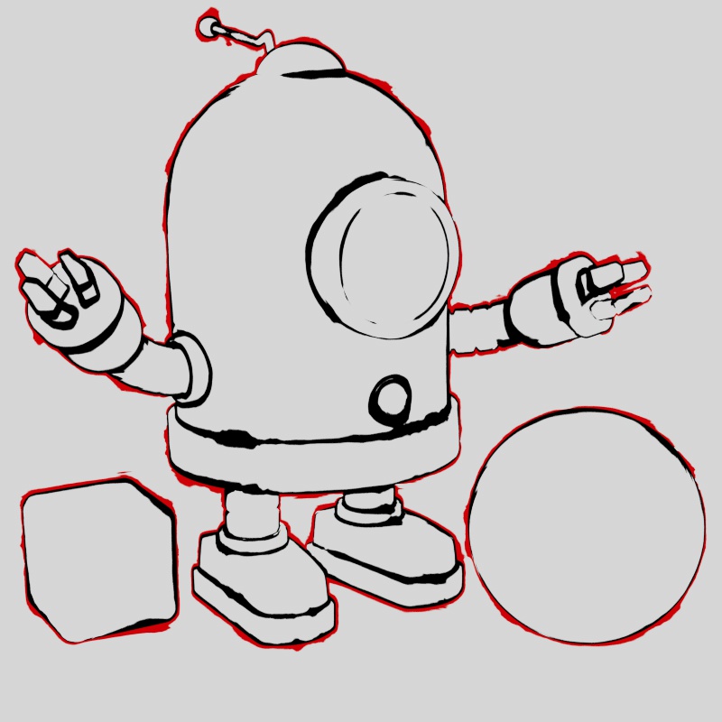
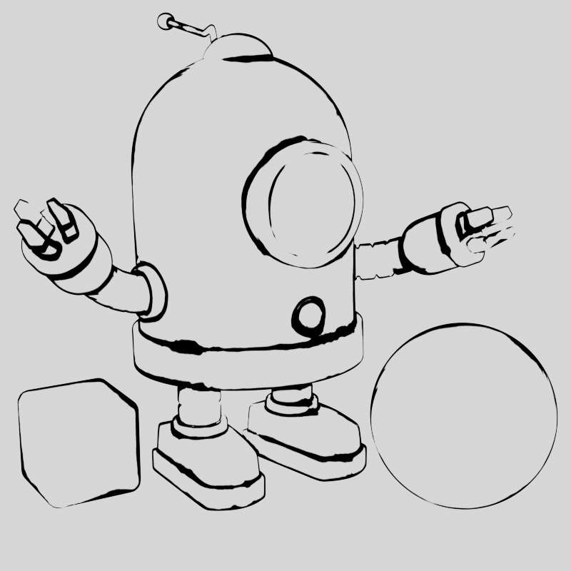
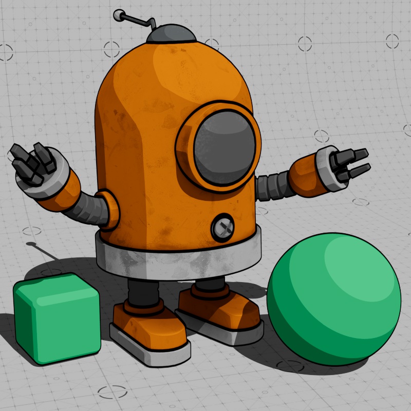
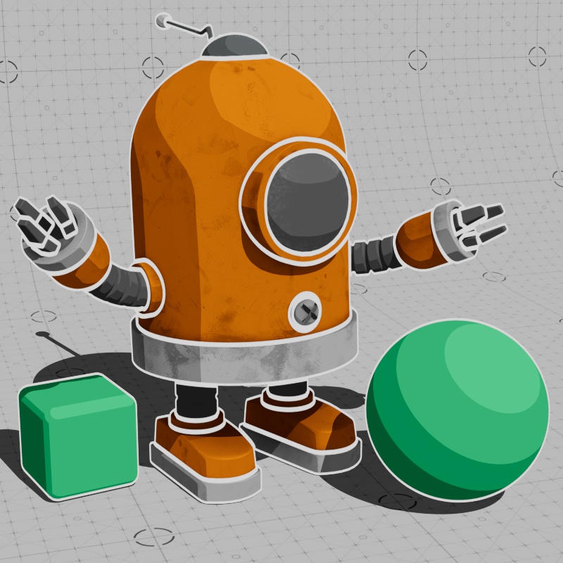
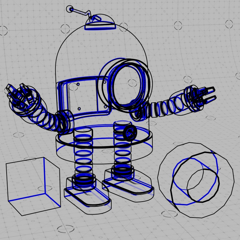
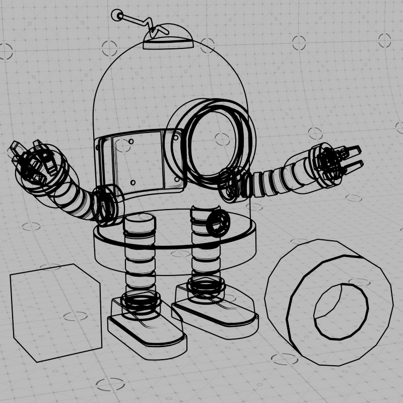
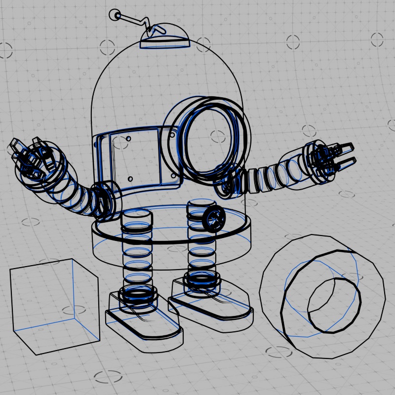
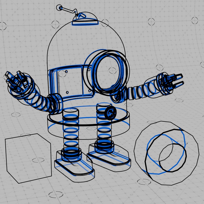
A scene can exhibit many different scenarios and understanding how contours behave in different conditions is important to getting the most out of them. To start with the basics, External Lines draw a line around the silhouette of an object while Internal Lines draw a silhouette and have the ability to draw lines along interior details of an object. Both types of lines can be used at the same time, however, external lines are always drawn on top of internal lines. In the examples below, external lines are black and internal lines are red, note how the red internal lines are still drawn around the silhouette of an object but they capture additional detail that external lines cannot. Line thickness and other settings have been exaggerated to make the differences readily apparent, thin lines are generally better for more small details.

|
|

|
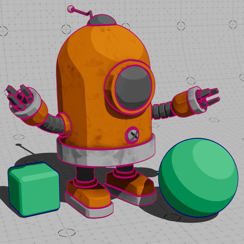
| External Lines | Internal Lines | External and Internal Lines |
However, if an internal line is thicker than an external line it will peek out from under the external lines. In the example below, the black external lines have a thickness of 10 and the red internal lines are animated from a thickness of 0 all the way up to 20. Around the half way point of the animation both lines have the same thickness, but as the thickness continues to climb the red internal lines can be seen next to the external lines along the silhouette of the object.
| Internal Line Thickness: 0 - 20 External Line Thickness: 10 |
How your objects are constructed also has an impact on the appearance of contour lines. Since external lines only draw a line around the silhouette of an object, there can be a large difference between whether your objects are combined into a single mesh or made up of several smaller objects. In the example below, the robot model has been combined into a single mesh which completely changes where the black external lines are visible. By comparison, the red internal lines occupy the same general location but they are now uncovered in many areas.
|

|
| Separate objects | Combined into one mesh |
Intersections and Overlaps
Contours can behave differently when other objects intersect with or render in front of an object with a contour, this is dependent on the Detect Separate Meshes parameter. By default, when set to "Off," overlapping and intersecting objects do not create contours.

|

|
| Overlapping objects Detect Separate Meshes: Off (default) |
Intersecting objects |
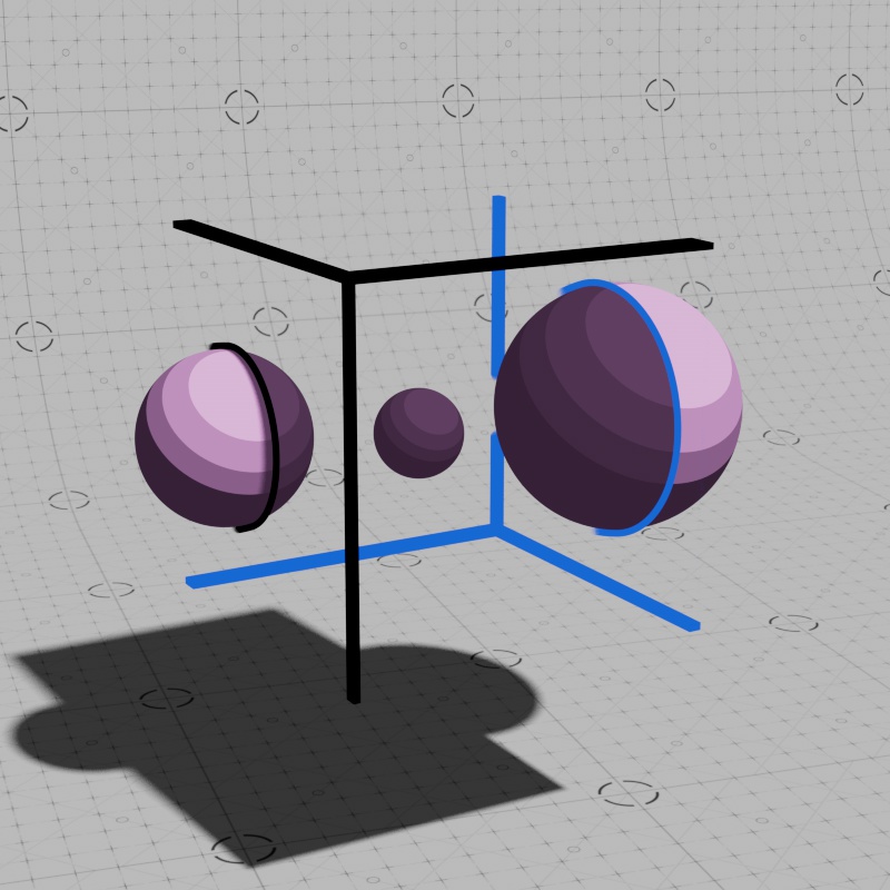
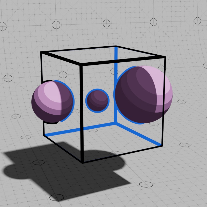
However, when Detect Separate Meshes is set to "Overlapping and Intersecting," contours are drawn around the silhouette of overlapping objects and along any mesh intersections. Note that the contour does not draw on top of the overlapping or intersecting object — the blue spheres in the example below — the contour is only drawn on the object that has contours applied to it.
You can also isolate these effects from each other by using either the "Intersecting" or "Overlapping" modes. However, these modes are only approximations and do not guarantee that two objects actually intersect with each other. Scene scale has an impact on the accuracy of these modes, try increasing the scale of your objects or using the "Overlapping and Intersecting" mode for the most stable results.
|
|
| Overlapping objects Detect Separate Meshes: Overlapping and Intersecting |
Intersecting objects |
Breaking Boundaries
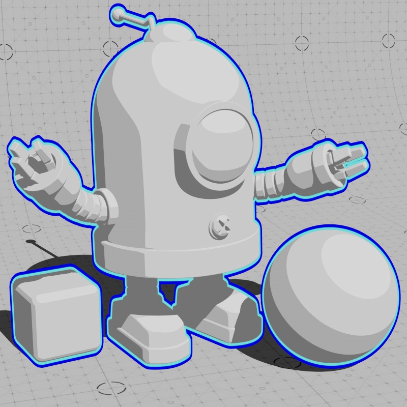
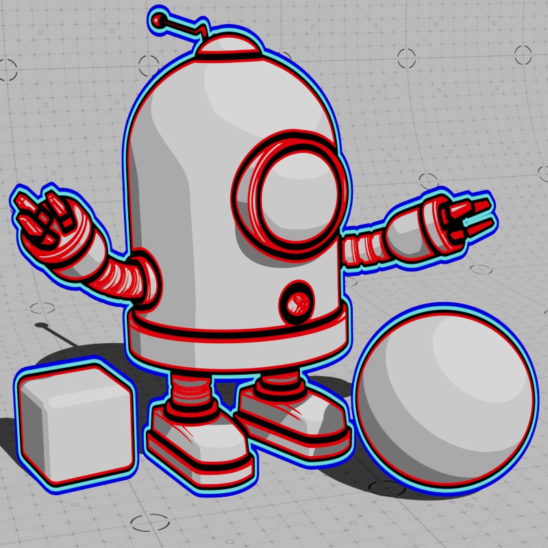
Contours cannot be drawn outside the bounds of the objects that they are applied to, but it is possible to create a visual illusion that contours are rendered outside the bounds of an object. Since an object passing in front of an object with contours causes a line to be drawn, this can be leveraged to create a convincing effect that contours have no limits. Essentially, this requires all objects in a scene to use contours, and most importantly, that a background object uses contours so that the edges can be drawn anywhere outside the bounds of an object that appears in front of that background.
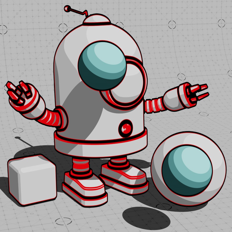
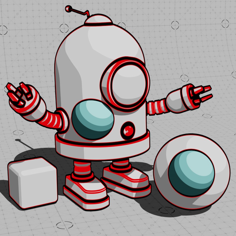
In the examples below, the foreground objects have red internal lines and black external lines, while the background cyke object has dark blue internal lines and light blue external lines.
|
|
|
| Foreground Contours | Background Contours | Foreground and Background Contours |
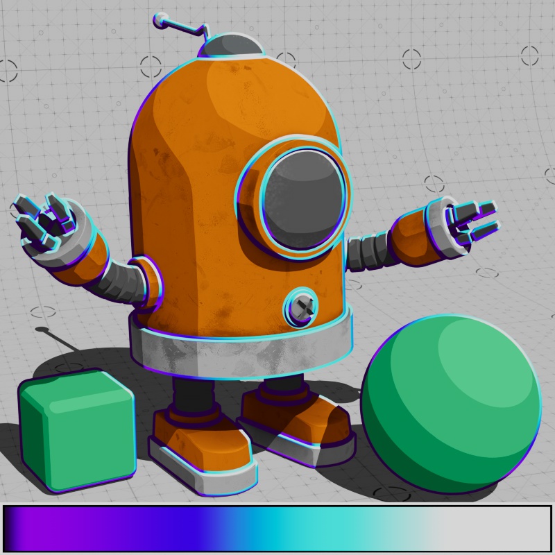
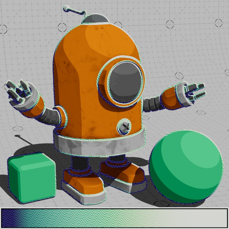
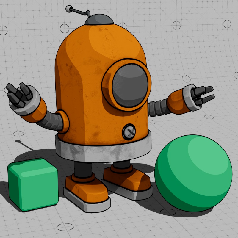
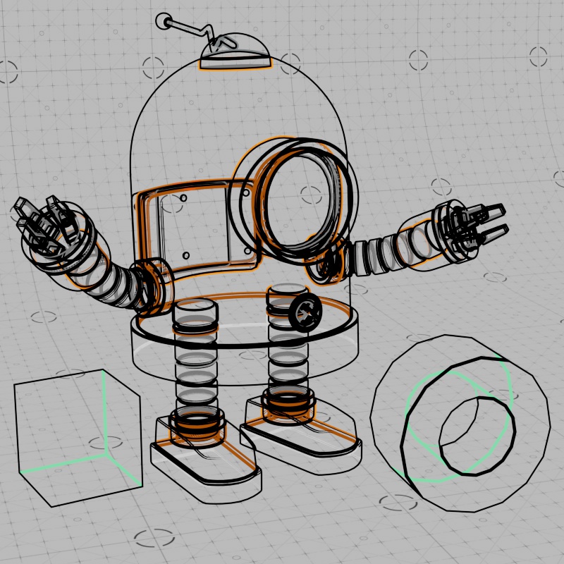
With all the different colors, this can start to look like a bit of a visual mess — however, we can leverage this behavior and use it to our advantage to create very stylized looks. In general, this trick works best with contours that have the same color so the difference between foreground and background object contours cannot be distinguished. In the example below, all contours use the same Maxon noise texture to control the thickness modifier, allowing for variable width lines. In the first example, there is no way to distinguish between foreground or background contours resulting in the illusion that the lines are breaking out of the boundary of the foreground objects resulting in a very stylized effect. In the middle example, the background contours have been changed to red to demonstrate the difference. In the last example you can see how the scene looks if no background contours are used, the foreground contours are cleanly cut off along the silhouette of the objects.
|
|
|
| Foreground Contours: Black Background Contours: Black |
Black Red |
Black No Background Contours |
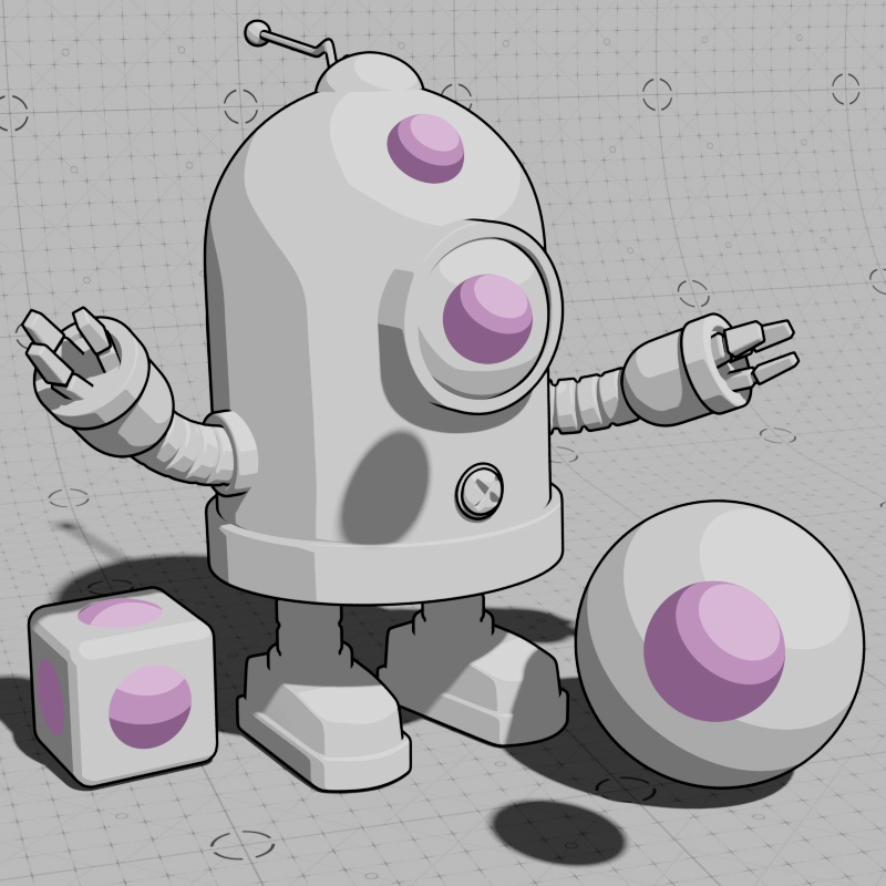
Combined with a toon shader and a bump map to distort the tone mapping it is possible to bring all these elements together for different artistic looks.
|
|
Global Contours
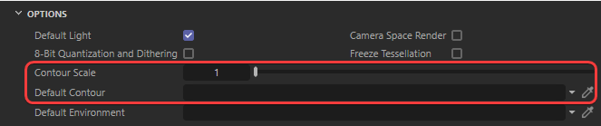
Redshift offers two ways to control contours across your entire scene. These options can be found in the Render Setting's Global tab as pictured below.
|
The Contour Scale option scales the thickness of all contours in the scene as a multiplier value. For example, if you have two contours in your scene and one is set to a thickness of 3 and the other is set to 5, with the Contour Scale set to 2.5 the new thicknesses would be equivalent to 7.5 and 12.5.
The Default Contour feature lets you connect a material with a contour node that is applied to all objects in the scene. The Default Contour has no effect on materials that have their own contour setup at the local material level. The Default Contour is a great way to manage contours for background elements and then use more specialized contours for hero assets.
When using the Default Contour feature but you want a material to have no contours at all, connect a contour to that material and disable Internal and External contours manually.
Parameters
General
|
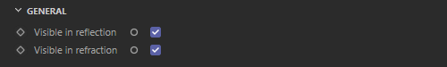
Visible in Reflection
Controls if contours are visible in reflections. Disabling Visible in Reflection stops contours from appearing in reflections, this includes self reflections.
In the examples below, a rough mirror is placed next to the toon objects. When disabled, contours cannot be seen in the mirror.

|

|
| Visible in Reflections: Enabled (default) | Disabled |
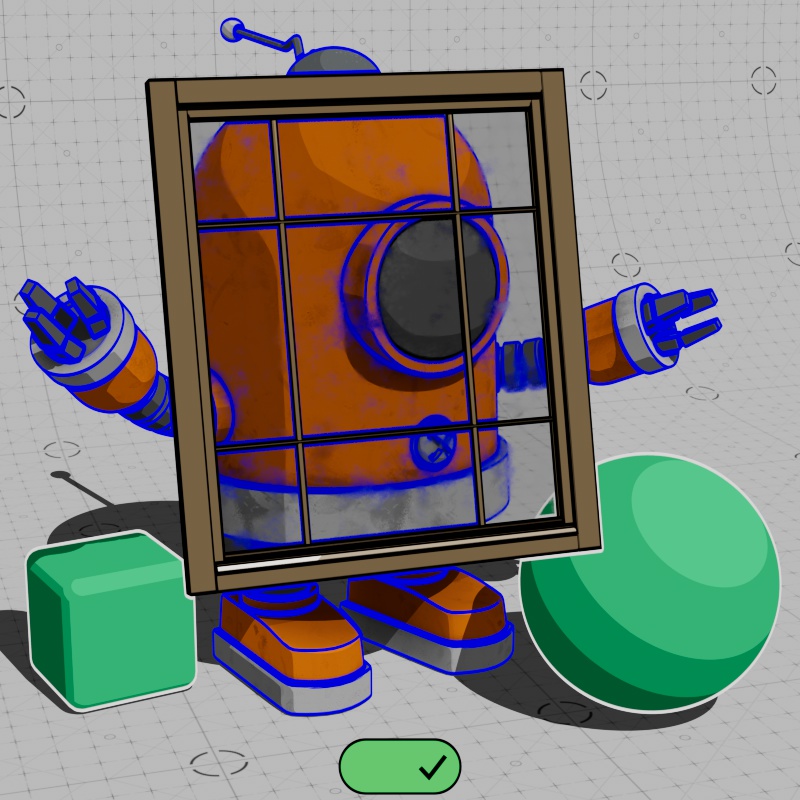
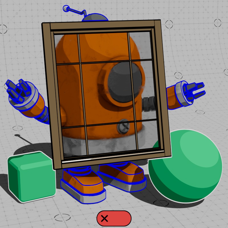
Visible in Refraction
Controls if contours are visible in refractions. Disabling Visible in Refraction stops contours from appearing in refractions, including self refractions.
In the examples below, a smudged transmissive window is placed in front of the toon objects. When Disabled, contours cannot be seen through the glass.
|
|
| Visible in Refractions: Enabled (default) | Disabled |
External
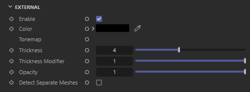
|
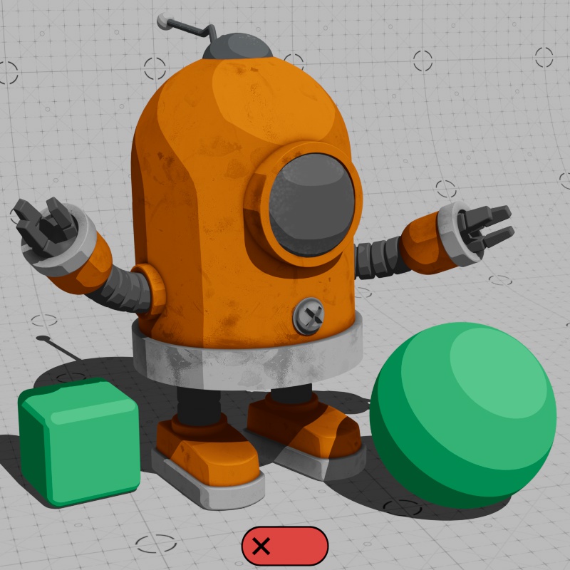
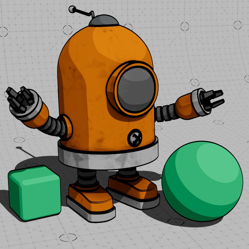
Enable
Enables or disables contour lines drawn around the silhouette of an object.

|
|
| External Line: Enabled | Disabled |
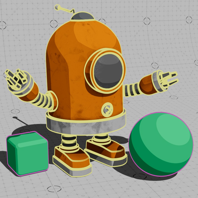
Color
Sets the color of external lines. This can also be driven by a texture.
|
|
|

|
| External Line Color: Black | White | Pink and Blue | Textured |
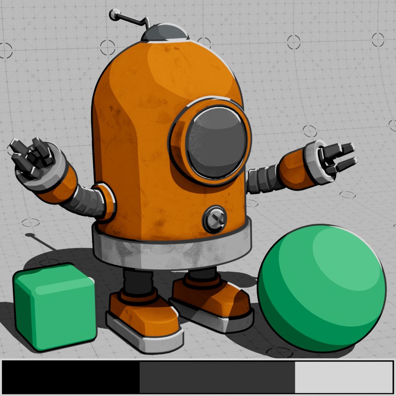
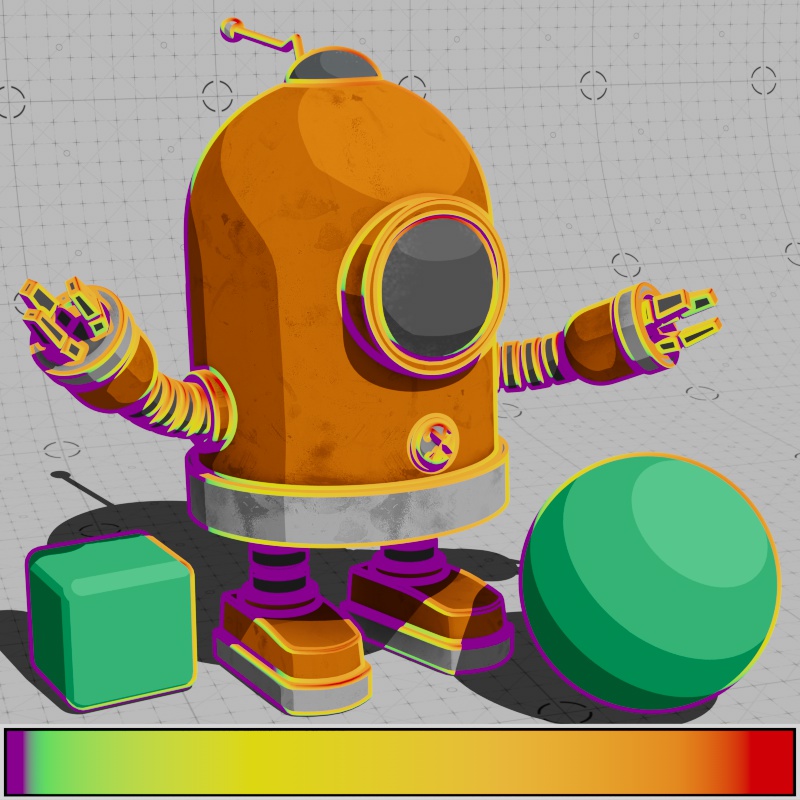
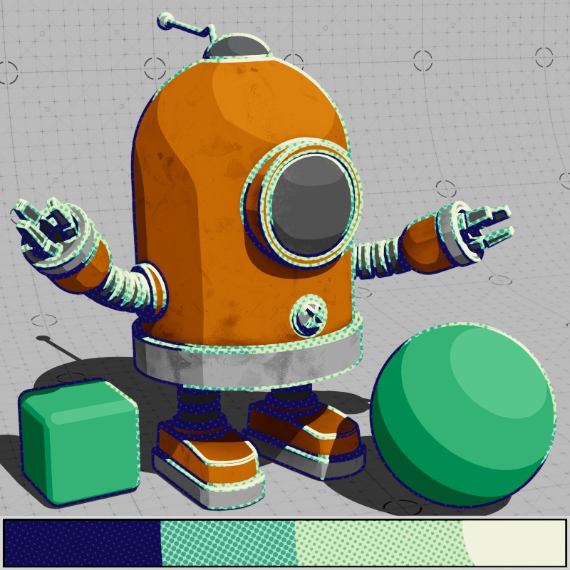
Tonemap
Controls the shading with an externally connected ramp or texture node, this is where you can give contours a shaded look. Using a ramp with stepped interpolation results in a classic cel shaded look where the transition between highlight and shadow is abrupt and sharp. The External Tonemap color is multiplied with the External Color — so the External Color must be brighter than black in order to see any shading effect.
Tone mapping works by mapping the light intensity on the objects in your scene (the illuminance) to a ramp node with colors and shading defined by you. With a horizontal ramp, the left side of the ramp controls the shadow color, the middle part of the ramp controls the midtone colors, and the right part of the ramp controls the highlight color.
Tone mapping on the Contour shader works exactly like the Base Tonemap on the Toon material. For more detailed information,
Ramp nodes are automatically used as a tonemap when they are connect to a Tonemap input.
|
|
|
| Tonemap Input: Stepped Ramp | Colorful Ramp | Tonemap Pattern |
Thickness
Controls the maximum thickness of the external lines. The Thickness parameter only accepts a constant value, to vary the thickness use the Thickness Modifier instead.
The thickness parameter is measured in pixels for a 1920x1080 resolution image, rendering in other resolutions rescales the thickness automatically so that it appears to have the same relative thickness at any resolution.
External lines will cover up Internal and Backfacing lines if they are thicker and occupy the same location.
The width of all contour lines in a scene can also be scaled with the Contour Scale option found in the Globals tab of the Render Settings.

|

|
|

|
| External Line Thickness: 0 | 3 | 8 | 15 |
Thickness Modifier
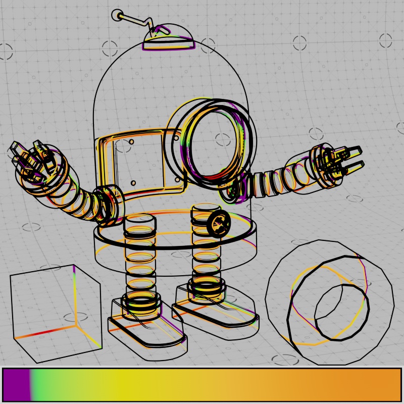
Changes the width of the external lines, connect a texture here to vary the thickness along external lines. Lower values decrease the width of a line, with 0 resulting in no visible thickness, while higher values increase the width and a value of 1 results in full thickness. The maximum width of a line is always limited by the Thickness parameter, increase the overall thickness in order to give yourself more room for thickness variation.
| Thickness Modifier: Maxon Noise with animated color |
Animated Texture |
Opacity
Controls the opacity of external lines. Reducing the opacity reveals the base material underneath.

|

|

|
| Opacity: 0 | 0.5 | 1 |
Detect Separate Meshes
Controls if overlapping or intersecting meshes create contours for external lines from the following modes:
- Off – Contours are not drawn around objects that intersect with or appear in front of an object with contours.
- Intersecting – Contours are drawn around objects that intersect with an object with contours.
- Overlapping – Contours are drawn around objects that appear in front of an object with contours.
- Overlapping and Intersecting - Contours are drawn around objects that intersect with or appear in front of an object with contours.
The “Intersecting” and “Overlapping” modes are approximations and do not guarantee that two objects actually intersect with each other. Scene scale has an impact on the accuracy of these modes, try increasing the scale of your objects or using the “Overlapping and Intersecting” mode for the most stable results.
Contours only draw on the object with the contours applied, they cannot draw on top of the overlapping or intersecting objects unless they also have a contour shader applied to them.
|
|
|
|
| Detect Separate Meshes: Off (default) | Intersecting | Overlapping | Overlapping and Intersecting |
Internal
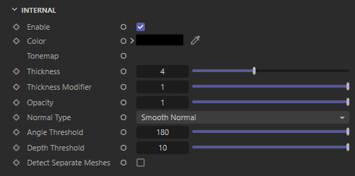
|
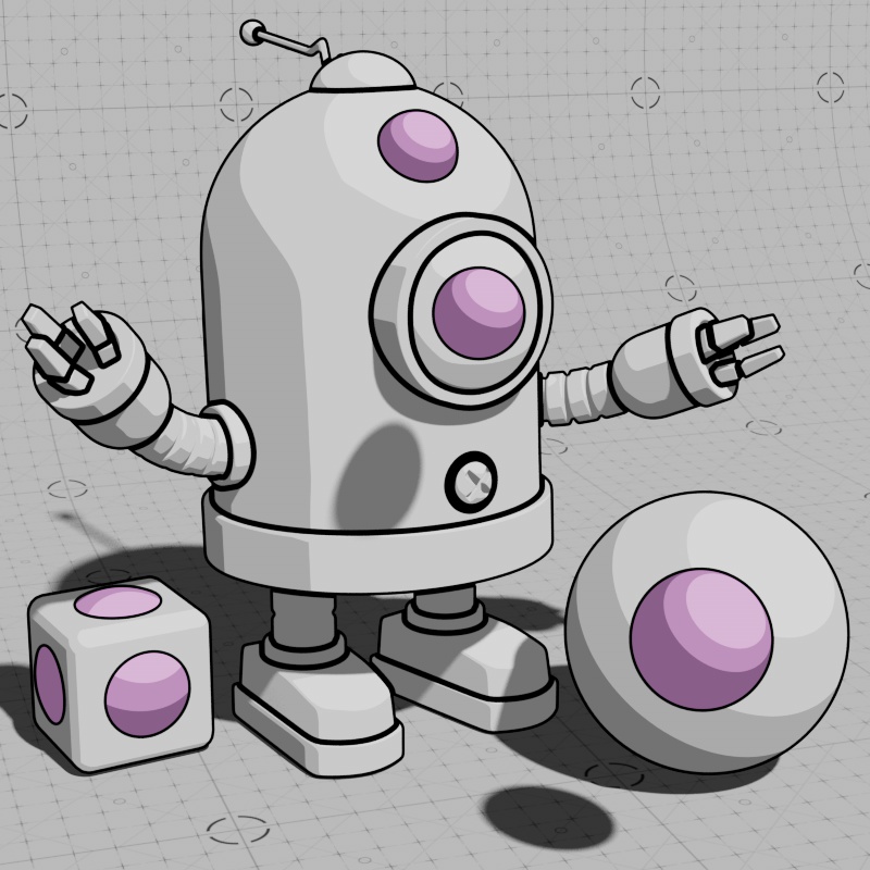
Enable
Enables or disables contour lines drawn along the prominent internal edges of an object. Use the Angle Threshold parameter to control which edges receive internal lines.

|

|
| Internal Line: Enabled | Disabled |
Color
Sets the color of internal lines. This can also be driven by a texture.

|

|
|

|
| Color: Black | White | Yellow and Pink | Textured |
Tonemap
Controls the shading with an externally connected ramp or texture node, this is where you can give contours a shaded look. Using a ramp with stepped interpolation results in a classic cel shaded look where the transition between highlight and shadow is abrupt and sharp. The External Tonemap color is multiplied with the Internal Color — so the Internal Color must be brighter than black in order to see any shading effect.
Tone mapping works by mapping the light intensity on the objects in your scene (the illuminance) to a ramp node with colors and shading defined by you. With a horizontal ramp, the left side of the ramp controls the shadow color, the middle part of the ramp controls the midtone colors, and the right part of the ramp controls the highlight color.
Tone mapping on the Contour shader works exactly like the Base Tonemap on the Toon material. For more detailed information,
Ramp nodes are automatically used as a tonemap when they are connect to a Tonemap input.

|
|
|
| Tonemap Input: Stepped Ramp | Colorful Ramp | Tonemap Pattern |
Thickness
Controls the maximum thickness of the internal lines. The Thickness parameter only accepts a constant value, to vary the thickness use the Thickness Modifier instead.
The thickness parameter is measured in pixels for a 1920x1080 resolution image, rendering in other resolutions rescales the thickness automatically so that it appears to have the same relative thickness at any resolution.
External lines will cover up Internal lines if they are thicker and occupy the same location.
The width of all contour lines in a scene can also be scaled with the Contour Scale option found in the Globals tab of the Render Settings.

|

|

|
| Thickness: 0 | 2 | 4 |
Thickness Modifier
Changes the width of the internal lines, connect a texture here to vary the thickness along internal lines. Lower values decrease the width of a line, with 0 resulting in no visible thickness, while higher values increase the width and a value of 1 results in full thickness. The maximum width of a line is always limited by the Thickness parameter, increase the overall thickness in order to give yourself more room for thickness variation.
| Thickness Modifier: Maxon Noise with animated color |
Animated Texture |
Opacity
Controls the opacity of internal lines. Reducing the opacity will reveal the base material underneath.

|

|
|
| Opacity: 0 | 0.5 | 1 |
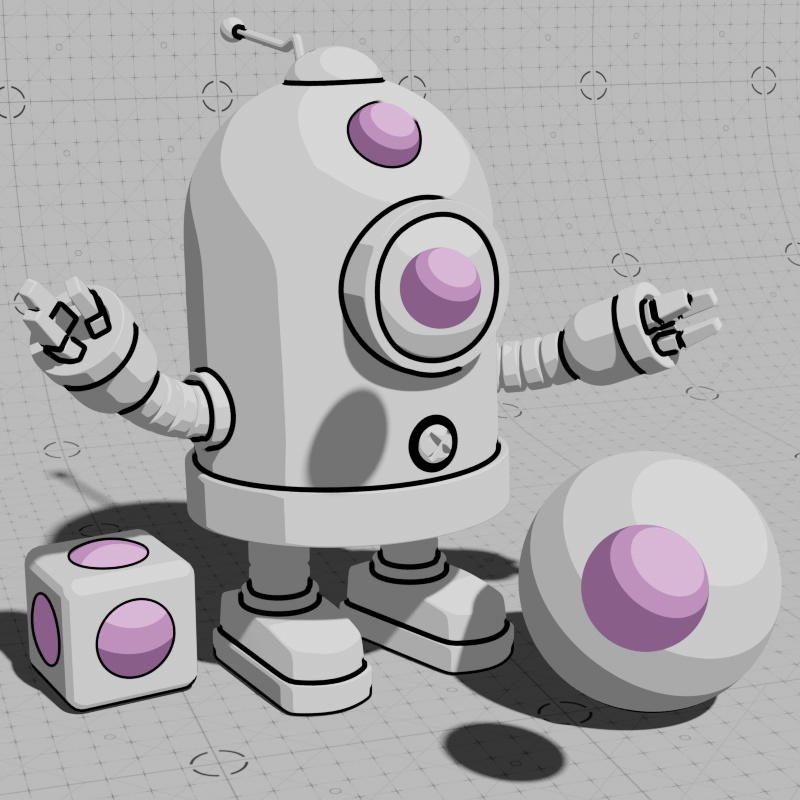
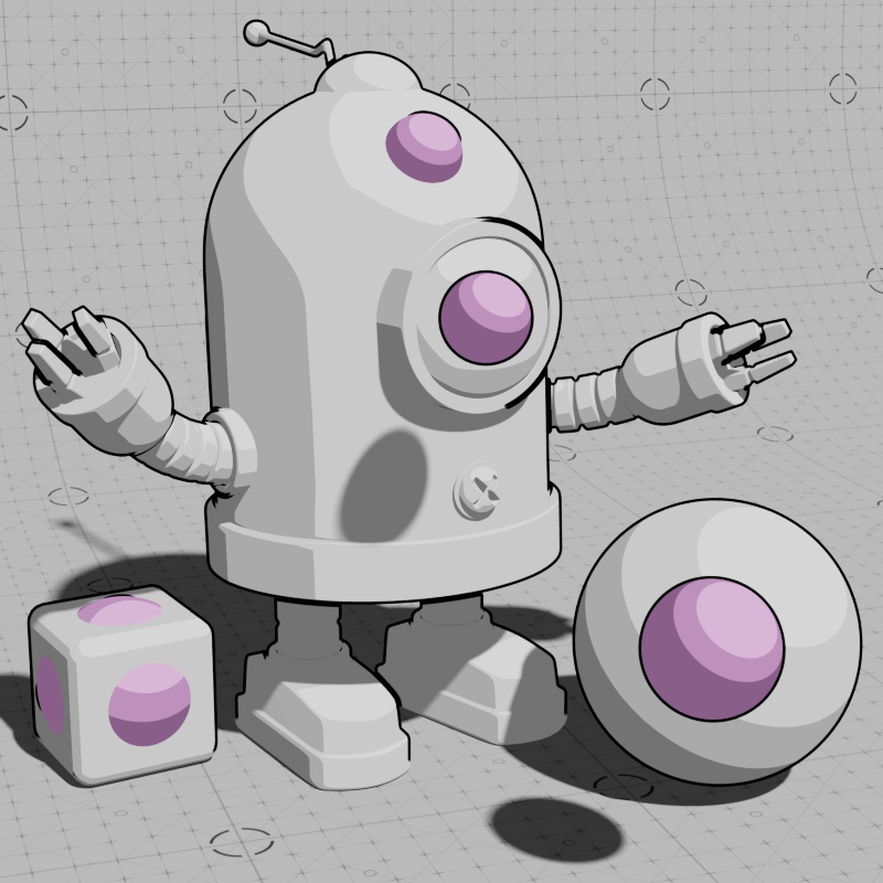
Normal Type
Controls the type of normal that is used for detecting internal edges.
When using Smooth Normal, by default, the shading normals are used which is commonly the best method as it will tend to capture the most prominent edges and detect edge breaks as long as the Angle Threshold is low enough.
When using Geometric Normals, the edges of each polygon are easily detected for line rendering. Using geometric normals can result in a wireframe style look at low Threshold values.

|

|
| Normal Type: Smooth Normal | Geometric Normal |
Angle Threshold
Controls when an internal line is detected and drawn based on the difference in angle between neighboring normals. Higher values result in fewer internal lines while lower values result in more lines. In general, it is recommended to start adjusting Angle Threshold to establish the main internal contours and then adjust Depth Threshold for additional control.
| Angle Threshold: 5 - 90 Normal Type: Smooth |
5 - 90 Geometric |
Depth Threshold
Scene Units
Controls how far apart two identically oriented faces can be in scene units before an edge is detected, this is based on z depth and the camera's angle. Higher values result in fewer edges being drawn because the faces need to be farther apart before edges can be detected. A value of 0 results in the internal lines covering the entire object. If you are already using a low Angle Threshold, changing this value may not result in much of a difference — balancing the two is important to finding the right look for your scene.
This parameter is in scene units, be certain to use values that make sense for your scene's scale. For example, if 10 is the selected Depth Threshold then only identically oriented faces beyond 10 scene units will be eligible for line drawing.
|
Depth Threshold: Increasing from 0 |
Increasing from 0 45 |
Detect Separate Meshes
Controls if overlapping or intersecting meshes create contours for internal lines from the following modes:
- Off – Contours are not drawn around objects that intersect with or appear in front of an object with contours.
- Intersecting – Contours are drawn around objects that intersect with an object with contours.
- Overlapping – Contours are drawn around objects that appear in front of an object with contours.
- Overlapping and Intersecting - Contours are drawn around objects that intersect with or appear in front of an object with contours.
The “Intersecting” and “Overlapping” modes are approximations and do not guarantee that two objects actually intersect with each other. Scene scale has an impact on the accuracy of these modes, try increasing the scale of your objects or using the “Overlapping and Intersecting” mode for the most stable results.
Contours only draw on the object with the contours applied, they cannot draw on top of the overlapping or intersecting objects unless they also have a contour shader applied to them.
|
|
|

|
| Detect Separate Meshes: Off (default) | Intersecting | Overlapping | Overlapping and Intersecting |
Advanced
|
Tonemapping
Mode
The Tonemap Modes controls how Tonemap shading behaves in shadow.
By default, using Light and Opaque Shadow, a shadow can dim or even change the color of the tone mapping underneath but all tone map transitions stay in the same place whether they are in or out of shadow. Lower opacity shadows make the underlying region brighter while more opaque shadows make it darker.
By comparison, the Light and Shadow mode actually changes how tone mapping is applied when in shadow and adheres strictly to the colors used in the connected tonemap. In this mode, a shadow shifts the tone mapping along the tonemap ramp — more opaque shadows shift the tone mapping further into the shadow part of the ramp.
Tone mapping on the Contour shader works exactly like the Base Tonemap on the Toon material. For more detailed information,
| Light and Opaque Shadow (Default) |
||
| Light and Shadow | ||
| Tonemap Mode | Tonemap Input: Stepped Ramp Shadow Opacity: -1 to +1 Situation: Partially in shadow |
Stepped Ramp -1 to +1 Fully in shadow |
Shadow Opacity
Offsets the transparency level of shadows that are cast on a tone mapped object. Note, the overall tone mapping behavior when in shadow is controlled by the Tonemapping Mode.
By default, using a value of 0, the shadow opacity is determined by each light's Shadow Transparency.
Values below 0 reduce the shadow opacity with -1 resulting in no cast shadows.
Values above 0 increase the shadow opacity with +1 forcing all shadows to their darkest tone mapped value.
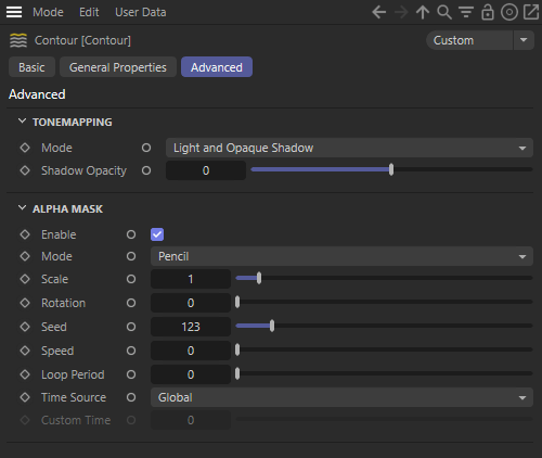
Alpha Mask
Enable
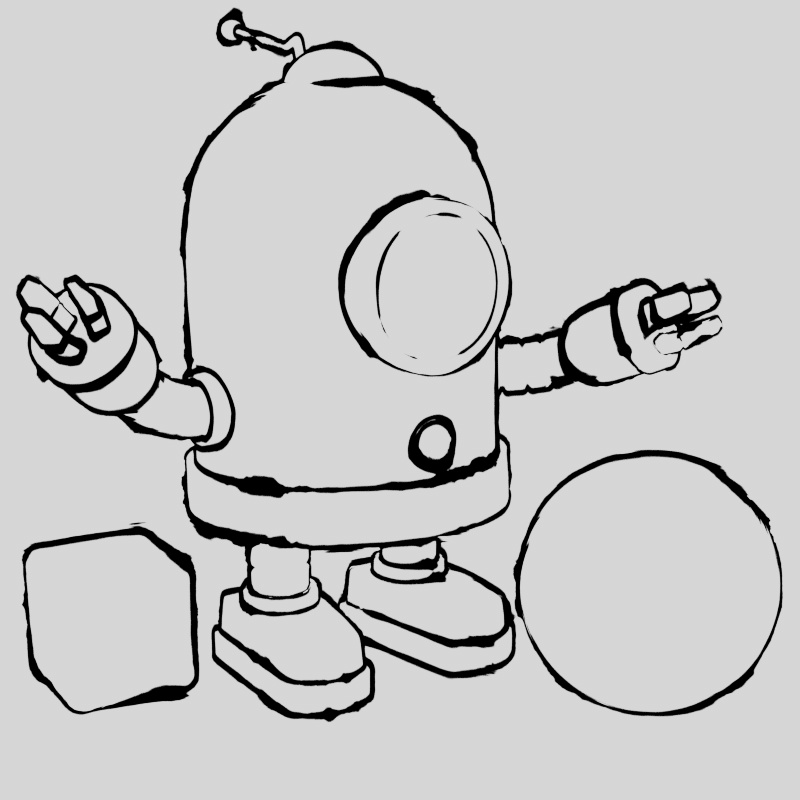
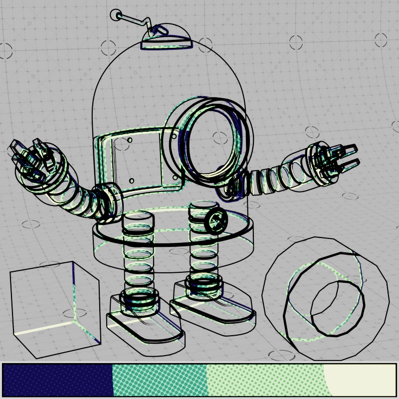
Enables or disables the Alpha Mask feature for quick stylization of contours.
Mode
Controls which stylization to use to use for the contour Alpha Mask from the following options:
-
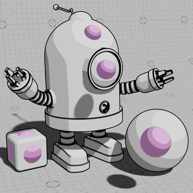
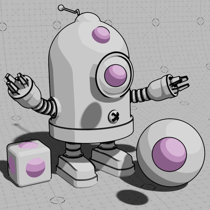
Pencil - Emulates a graphite pencil look with a consistent width, rough edges, and infrequent but harsh opacity texture variation.
-
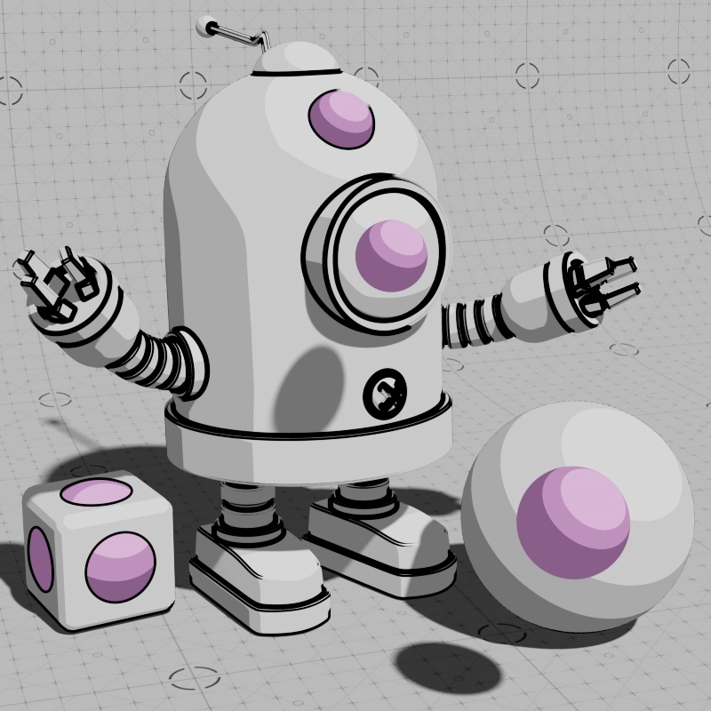
Fountain Pen - Emulates a fountain pen look with a highly variable width, softer edges, and frequent but more subtle opacity texture variation

|

|
| Mode: Pen | Pencil |
Scale
Controls the scale of the noise texture used to drive the Alpha Mask.
| Scale: 0 - 1 Mode: Pen |
Pencil |
Rotation
Rotates the noise texture used to drive the Alpha Mask.
| Rotation: 0 - Mode: Pen |
Pencil |
Seed
Sets the random seed for the noise texture used to drive the Alpha Mask. Animating this value is a great way to add randomization to your contours over time.
| Seed: Animated Mode: Pen |
Pencil |
Speed
Controls how fast the noise texture used to drive the Alpha Mask animates in cycles per second. A value of 0 results in no animation.
| Speed: 0.5 Mode: Pen |
1 |
2 |
Loop Period
Controls how often the Alpha Mask texture loops in seconds.
This is computed from Frame number divided by FPS. For example, if 0.5 is entered the noise loops every 0.5 seconds which would be every 15 frames in a 30 FPS project or every 30 frames in a 60 FPS project.
Time Source
Controls what source is used to determine the Alpha Mask's time frame from the following options:
-
Global (default) - Uses the project's timeline and the frames per second setting as the time source for Alpha Mask animation.
-
Custom - Uses the Custom Time parameter as the time source for noise animation.
Custom Time
When Time Source is set to Custom, this value can be manually animated to control the Alpha Mask's animation in seconds. Each integer value is equivalent to that number in seconds, for example, a value of 2 is equivalent to two seconds and a value of 4.5 is equivalent to four and a half seconds.
Backfacing
Enable
Enables or disables contour lines drawn along the back facing internal edges of an object. Use the Angle Threshold parameter to control which edges receive back-facing lines.

|

|
| Backfacing Lines: Enabled Backfacing Line Color: Blue External and Internal Line Color: Black |
Disabled |
Color
Sets the color of back-facing lines. This can also be driven by a texture.

|

|
|
|
| Color: Black | White | Blue | Textured |
Tonemap
Controls the shading with an externally connected ramp or texture node, this is where you can give contours a shaded look. Using a ramp with stepped interpolation results in a classic cel shaded look where the transition between highlight and shadow is abrupt and sharp. The Backfacing Tonemap color is multiplied with the Backfacing Color — so the color must be brighter than black in order to see any shading effect.
Tone mapping on the Contour shader works exactly like the Base Tonemap on the Toon material. For more detailed information,
Ramp nodes are automatically used as a tonemap when they are connect to a Tonemap input.

|
|
|
| Tonemap Input: Stepped Ramp | Colorful Ramp | Tonemap Pattern |
Thickness
Controls the maximum thickness of the back-facing lines. The Thickness parameter only accepts a constant value, to vary the thickness use the Thickness Modifier instead.
The thickness parameter is measured in pixels for a 1920x1080 resolution image, rendering in other resolutions rescales the thickness automatically so that it appears to have the same relative thickness at any resolution.
External and Internal lines will cover up Backfacing lines if they are thicker and occupy the same location.
The width of all contour lines in a scene can also be scaled with the Contour Scale option found in the Globals tab of the Render Settings.
|
|

|
| Thickness: 0 | 2 | 4 |
Thickness Modifier
Changes the width of the back-facing lines, connect a texture here to vary the thickness along the lines. Lower values decrease the width of a line, with 0 resulting in no visible thickness, while higher values increase the width and a value of 1 results in full thickness. The maximum width of a line is always limited by the Thickness parameter, increase the overall thickness in order to give yourself more room for thickness variation.
| Thickness Modifier: Animated Maxon Noise |
Opacity
Controls the opacity of back-facing lines.

|

|

|
| Opacity: 0 | 0.5 | 1 |
Normal Type
Controls the type of normal that is used for detecting back facing internal edges.
When using Smooth Normal, by default, the shading normals are used which is commonly the best method as it will tend to capture the most prominent edges and detect edge breaks as long as the Angle Threshold is low enough.
When using Geometric Normals, the edges of each polygon are easily detected for line rendering. Using geometric normals can result in a wireframe style look at low Threshold values.
|

|
| Normal Type: Smooth Normal | Geometric Normal |
Angle Threshold
Controls when a back facing internal line is detected and drawn based on the difference in angle between neighboring normals. Higher values result in fewer lines while lower values result in more lines. In general, it is recommended to start adjusting Angle Threshold to establish the main internal contours and then adjust Depth Threshold for additional control.
| Angle Threshold: 5 - 90 Normal Type: Smooth |
5 - 90 Geometric |
Depth Threshold
Scene Units
Controls how far apart two identically oriented faces can be in scene units before an edge is detected, this is based on z depth and the camera's angle. Higher values result in fewer edges being drawn because the faces need to be farther apart before edges can be detected. A value of 0 results in the back-facing lines covering the entire object. If you are already using a low Angle Threshold, changing this value may not result in much of a difference — balancing the two is important to finding the right look for your scene.
This parameter is in scene units, be certain to use values that make sense for your scene's scale. For example, if 10 is the selected Depth Threshold then only identically oriented faces beyond 10 scene units will be eligible for line drawing.
|
Depth Threshold: Increasing from 0 |
Detect Separate Meshes
Controls if overlapping or intersecting meshes create contours for back-facing lines from the following modes:
- Off – Contours are not drawn around objects that intersect with or appear inside of an object with contours.
- Intersecting – Contours are drawn around objects that intersect with the back-face of an object with contours.
- Overlapping – Contours are drawn around objects that appear inside of an object with contours.
- Overlapping and Intersecting - Contours are drawn around objects that intersect with or appear inside of an object with contours.
The “Intersecting” and “Overlapping” modes are approximations and do not guarantee that two objects actually intersect with each other. Scene scale has an impact on the accuracy of these modes, try increasing the scale of your objects or using the “Overlapping and Intersecting” mode for the most stable results.
Contours only draw on the object with the contours applied, they cannot draw on top of the overlapping or intersecting objects unless they also have a contour shader applied to them.
In the example images below the Back-facing contours use a blue color while External and Internal lines are both black. The same mode is used for all three contour types in each example, so their behavior changes as well.

|
|
|

|
| Detect Separate Meshes: Off (default) Backfacing Contours: Blue External and Internal Contours: Black |
Intersecting | Overlapping | Overlapping and Intersecting |