The Render Settings
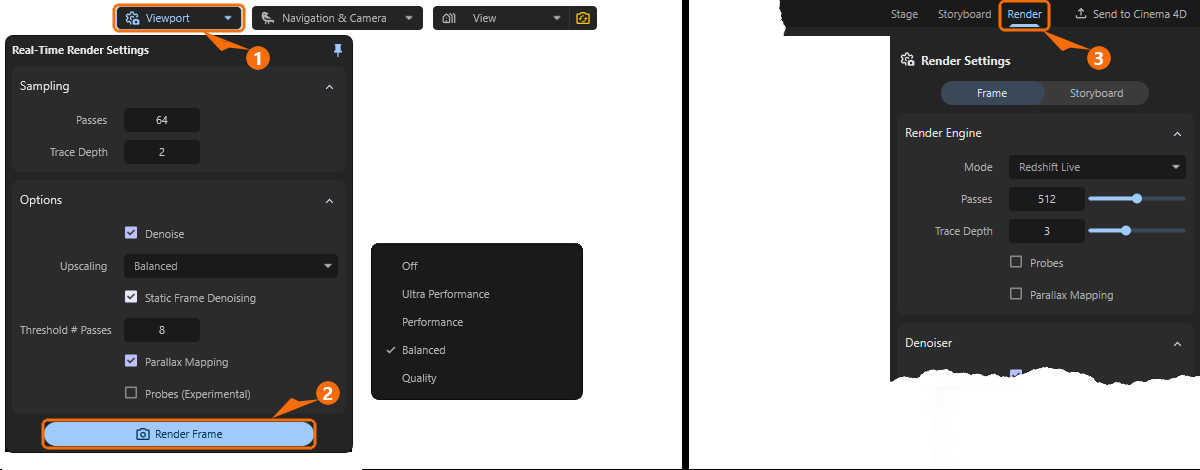
Maxon Redshift offers various quality levels and methods for displaying the scene in the viewport and for the final image or animation output, i.e. for rendering. Lower quality levels are generally used for the viewport, as the focus here is on fast interaction with the scene. The Viewport button (see 1 in Figure 1) at the top of the viewport gives you access to the corresponding presets for viewport rendering. By clicking on the Render Frame button (see 2 in Figure 1), which can also be found there, or alternatively by switching to the Render layout (see 3 in Figure 1), you can then also access the other render settings, which are used to define the methods and quality levels for the saved image output.
Maxon Redshift offers various methods for image calculation. Redshift Live, which is used by default in the viewport, can also be used for final image output, but due to its optimizations for the smoothest possible real-time display, it makes some compromises in the evaluation of material properties. If high quality is required and real-time rendering is not necessary, the Redshift Production renderer is available, which fully supports all material properties and physical effects. Due to these different objectives of the Live and Production Renderers, the saved frames can differ from the representations in the real-time viewport.
Learn more about the differences between the two rendering methods in this section.
Quick Navigation
Viewport Render Settings
By using the Viewport button in the viewport you can access the Viewport Render Settings (also see left side of Figure 1 above). There you can specify the rendering methods and quality levels to be used for live rendering in the viewport. These settings are therefore irrelevant for the final image or animation output. Separate render settings are available for this purpose, e.g., after clicking the Render Frame button (see 2 in Figure 1).
Let's take a look at the viewport render settings one by one.
Sampling
These settings mainly control the quality of the calculation per rendered pixel. Please note that usually only a reduced version of the scene area displayed in the viewport is rendered and then upscaled. The resolution used for viewport rendering is selected separately in the following Options group with the Upscaling mode. Very high sampling settings in combination with very high upscaling may therefore not necessarily reach their full potential. It is therefore often necessary to find a balance between the rendered viewport resolution and the quality selected via Sampling. The default values should already be sufficient for most cases.
Passes
The live renderer in the viewport uses a progressive rendering technique. Rendering is performed in several Passes, which are initially noisy and become increasingly clear. The Passes value specifies the number of progressive render passes until rendering should automatically end. More Passes will reduce the amount of noise in the viewport.
Please note that this number of Passes can only be rendered in a static viewport. While navigating or moving lights or objects, only a fraction of these passes may be used in order to provide feedback on the changes in your scene as quickly as possible. Rendering will then use the full number of Passes again as soon as your viewport remains static for a short period of time.
Often, even very small Passes values can still generate usable images when combined with the Denoise option for noise reduction.
Trace Depth
This setting is particularly relevant when light needs to be reflected between surfaces multiple times in order to reach all corners of the scene. Only with sufficient light transfer through reflections can a realistic, diffuse light distribution be calculated. The Trace Depth value only specifies the maximum number of light reflections. Whenever, for example, a dark material, a light source or the sky environment is hit by a calculation ray, the calculation automatically ends there. In general, however, the higher the Trace Depth, the more realistic the light distribution can be calculated and the longer the rendering can take overall (see also Figure 3 for comparison).
While outdoor scenes illuminated by large light sources, such as the sky or an HDRI, often achieve sufficiently good results even with small Trace Depth values, increasing the Trace Depth is often helpful when rendering interiors with correspondingly small light sources in order to achieve realistic light distribution (see Figure 4).
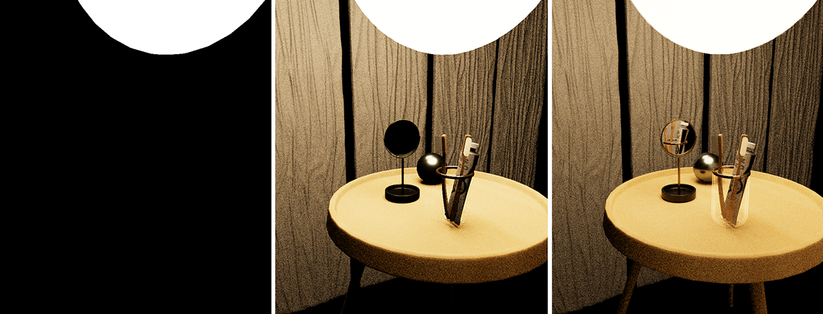
As can be seen in the sequence of images above in Figure 4, when illuminated by relatively small light sources, e.g., indoors, the small Trace Depth values are no longer sufficient to display a natural light distribution.
Especially when rendering interiors with only small light sources or windows through which outside light enters, increasing the Trace Depth can provide more realistic light distribution and illumination of the scene.
Options
These settings can be used to influence the calculation method used for viewport rendering.
Denoise
As already mentioned in the presentation of the Sampling settings, a relatively large number of calculation passes per image pixel are necessary to obtain a noise-free result. As an alternative to increasing the number of Passes, the Denoise option can also be activated. This activates access to the Upscaling setting, which further accelerates rendering, as only a fraction of the full resolution needs to be rendered. Denoising then additionally attenuates image noise through interpolation.
The advantages of viewport rendering with Denoise are:
- Viewport displays without visible noise even at low Passes values
- Additional acceleration features through the use of reduced viewport resolutions (see Upscaling)
But there are also disadvantages, of course, such as:
- Fine details can be lost when interpolating and scaling the rendering.
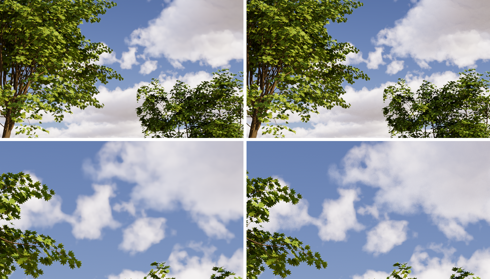
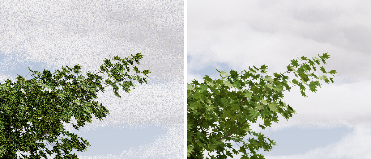
As a closer look at Figure 5 reveals, fine details can also fall victim to the Denoiser, especially when combined with aggressive Upscaling. However, this is often acceptable, especially in outdoor scenes, which are less prone to noise anyway due to large light sources.
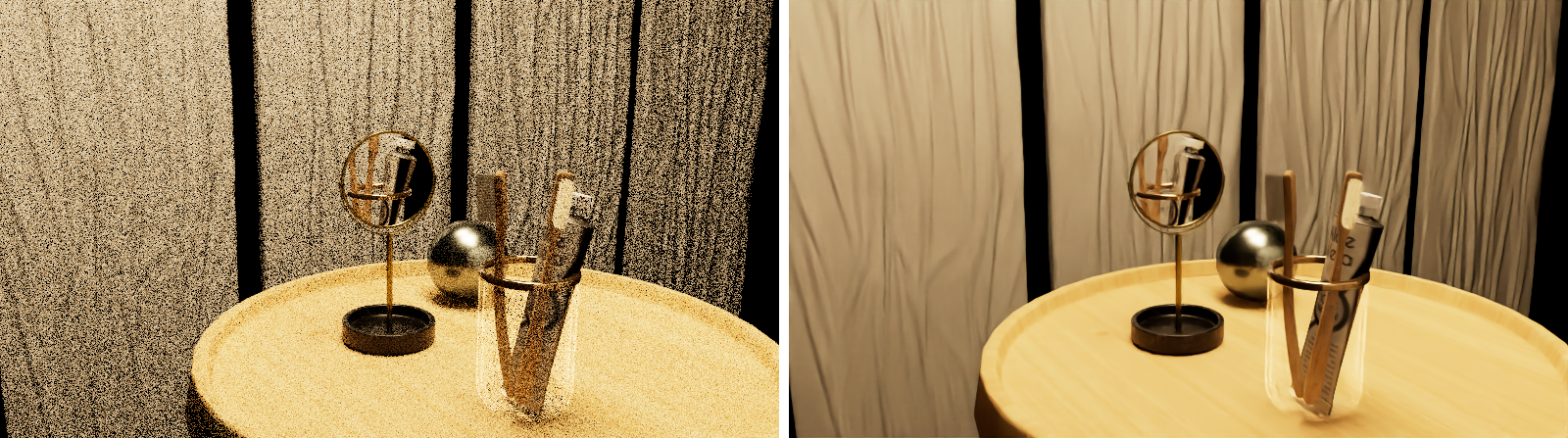
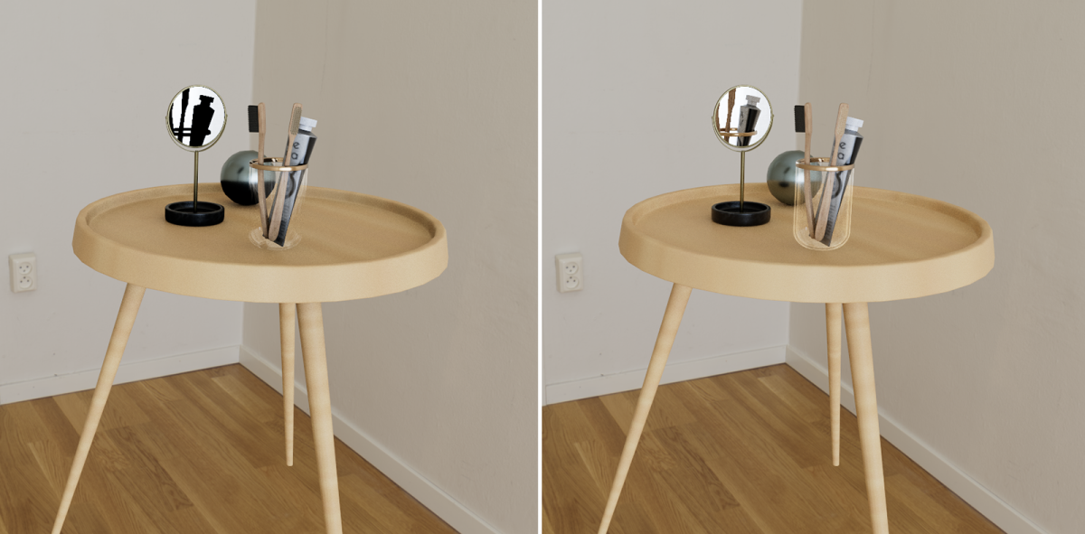
However, this observation may change for interior scenes, as these often require even more Passes to achieve a noise-free result. In these cases, Denoise can be very helpful in keeping render times short. Nevertheless, renderings with heavy noise can also be helpful, as fine details can still be discerned in them. For example, in Figure 6, despite the heavy noise, individual tufts of bristles can still be discerned on the toothbrushes, which appear more as a contiguous mass in the Denoise version.
It may therefore depend on the individual case whether you prefer to work with the denoised version or the slightly more precise version.
The Denoise algorithm activated here is optimized for continuously updated images, such as those that occur when navigating in the viewport. However, there are alternative denoisers for static images that can be even more effective. For this reason, Static Frame Denoising provides an additional denoising function that becomes active when the view in the viewport no longer needs to be redrawn, e.g., due to navigation.
Upscaling
In addition to the Passes and Trace Depth settings, which primarily determine the calculation quality of each pixel, the number of pixels to be calculated, i.e., the resolution of the viewport rendering, is naturally decisive for the required length of the calculation. For this reason, the Upscaling setting can also be used to render scaled down versions of the viewport, which are then upscaled to the full size again once the calculation is complete. Although this results in a slight blurring of the displayed viewport rendering, it saves a lot of time and is often sufficient to evaluate the materials and lighting of the scene adequately.
The Ultra Performance, Performance, Balanced, and Quality settings allow you to choose between different degrees of scaling, with Ultra Performance working with the smallest version of the viewport and therefore being correspondingly fast. However, with Off, you can completely skip any viewport scaling in order to use the full resolution.
In any case, it should be noted that Upscaling can only be used in conjunction with the Denoise option.
Static Frame Denoising
This option enables an alternative denoising filter — a feature optimized to process static content. This applies to situations where, for example, you do not need to move the camera or change the positions of objects for a few seconds.
Parallax Mapping
This option can evaluate a height map on materials to simulate depth and a displacement effect without having to generate additional polygons or subdivisions. The effect is similar to classic Bump Mapping or Normal Mapping, but can appear even more realistic. If supported by the materials used, this allows, for example, deep grooves between tiles or even blades of grass on a lawn to be rendered in real time on otherwise flat geometries.
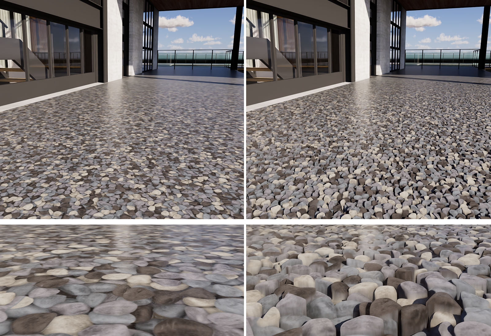
As can also be seen in Figure 7 below, Parallax Mapping also depends on the viewing distance and viewing angle and can therefore blur the perceptual boundaries between actually flat objects and real three-dimensional structures. Please note that the intensity of the Parallax Mapping effect is influenced by the Displacement Scale value of the material (see also this page about Materials).
Probes (Experimental)
This option uses an experimental estimate of where the lighting relevant to the scene comes from. In some cases, this allows for even more precise lighting simulation with fewer passes. If in doubt, simply try it out and see whether you prefer the result with or without this option. In conjunction with common Sampling values, the required rendering times are otherwise very similar.
Output Render Settings
The Render Settings discussed so far are only relevant for display in the viewport. Additional settings, which are then used for the final image calculation, can be accessed via the Viewport settings (see 1 in Figure 8) and clicking on their Render Frame button (see 2 in Figure 8) or by switching directly to the Render layout (see 3 in Figure 8).
Some of the settings there are identical to the Viewport Render Settings, but there are also additional options that can only be used for the final image output.
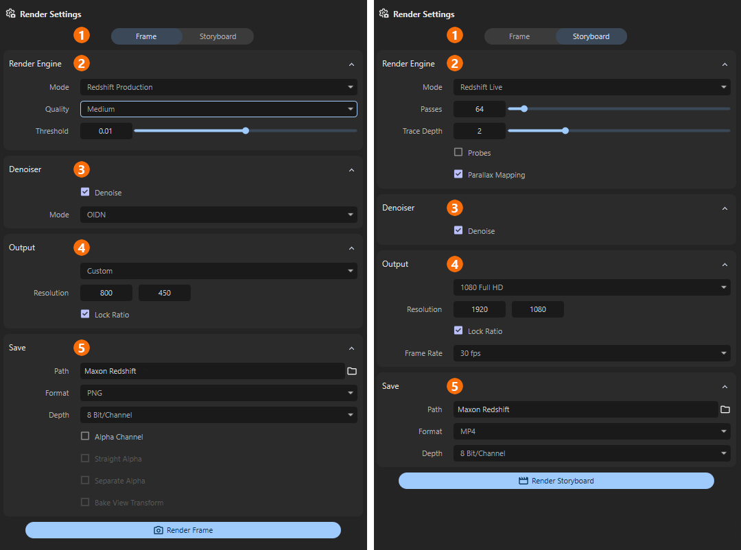
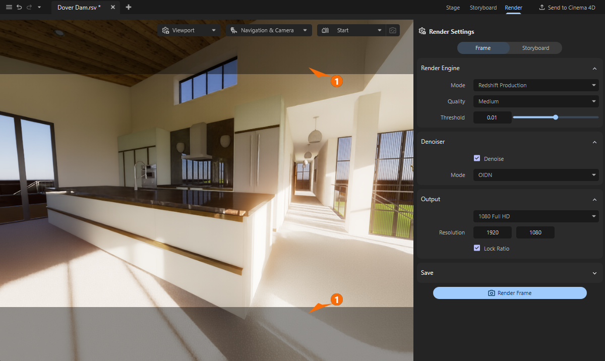
The categories of render settings listed in Figure 9 offer the following setting options:
1There are two Render Modes available here. Choose Frame to render still images or Storyboard to render an animation. For an animation, you must have Stored Views that you can arrange as desired within the Storyboard. The following Render Settings adapt to the render mode selected here.
2With the Render Engine you can select the method used to calculate the image or animation. You can choose between the same real-time mode you are already familiar with from the viewport display and a special production renderer that supports all material properties and effects.
3The Denoiser function can be used to automatically smooth out slightly noisy renderings. This can help reduce rendering times by allowing slightly lower quality levels to be selected for rendering.
4In the Output section, select the desired resolution and, when calculating animations, their frame rate.
5Finally, in the Save section, specify the file format and storage location for the finished images or videos.
Render Modes
Here you can specify whether only the perspective currently displayed in the Viewport should be rendered as a still image in the desired quality and resolution (Frame), or whether a sequence of images should be calculated that can then be played back as an animation or video (Storyboard). In Storyboard mode, the Storyboard Manager is evaluated, in which you arrange Stored Views in such a way that, for example, a camera movement is defined.
Render Engine
Mode
We already reviewed the real-time renderer used in the Viewport to display your scene. The same method can be used for final render as well, but for the best available quality, Production Mode should be used. Instead of rendering the image in multiple Passes, adding more details and image quality with every new Pass, small rectangular parts of the image are rendered one after each other (so called Buckets). By using these Buckets for rendering, memory requirements can be kept at a minimum, even for larger render resolutions.
Pros and Cons of the Live Renderer:
- + First iteration of the complete frame is available almost instantly, giving you the opportunity to evaluate the rendered scene even before it's totally finished.
- + Easy configuration, as increasing the Passes value will always enhance the quality of the rendering.
- + Easy to estimate the time needed to finish the rendering, as every Pass takes the same amount of time to finish
- + Parallax Mapping for the materials is only available for the Real-Time Renderer
- - Quality settings are not very efficient, as every area of the frame receives the same amount of Passes, no matter if it's a complex refractive material or just a plain colored wall.
- - Not all material features are supported. Features, like volumetric material properties are only available with Production Mode. To be more specific, these features are currently not supported by Live Rendering:
- No support for subsurface scattering (SSS)
- No support for rendering hair
- No rendering of point clouds
- No specular refraction
- No specular transmission in global illumination (GI)
- No tesselation free displacement (pixel displacement)
- No volume rendering
- No Spread parameter support for area lights
- No support for the Redshift Ray Switch material node
- No support for Redshift Trace Sets
- No support for light linking
- No soft shadow rendering for lights
- No Motion Blur rendering
- No Depth of Field rendering
- No support for thin walled meshes
- No AOV rendering (Arbitrary Output Variables)
Pros and Cons of the Production Renderer:
- + Efficient memory management.
- + Optimized render times, as the set Quality goal allows to handle every part of the frame independently.
- + All material and rendering features are supported (for instance, saved renderings can include Alpha Channels)
- - Rendering takes place Bucket after Bucket, only revealing the complete frame after all Buckets have been rendered.
- - The time needed to finish a frame cannot be estimated, as every Bucket can take a different time span to finish, based on the scene contents in that area.
Passes
This parameter is only available for the real-time renderer, because it uses a progressive rendering technique. Rendering is performed in several Passes, which are initially noisy and become increasingly clear. The Passes value specifies the number of progressive render passes until rendering should automatically end. Although more Passes always reduce noise in the final image, they also increase the time required to complete the rendering. Using the Denoise option helps to reduce the noise levels in the finished frame without having to increase Passes.
Since the same Passes value is also available for the Viewport Render Settings you can often use that value as a basis there and possibly increase it slightly to obtain the final quality for the saved rendering. Additional image examples for this parameter can also be found here.
Trace Depth
This setting is only available for the real-time renderer and is particularly relevant when light needs to be reflected between surfaces multiple times in order to reach all corners of the scene. Only with sufficient light transfer through reflections can a realistic, diffuse light distribution be calculated. As the same parameter is also used for the Viewport Render Settings, just can often just use the same value here as well, if you already like the light distribution in the Viewport. Additional image examples for this parameter can also be found here.
Probes
This option is only available for the real-time renderer and uses an experimental estimate of where the lighting relevant to the scene comes from. In some cases, this allows for even more precise lighting simulation with fewer passes. If in doubt, simply try it out and see whether you prefer the result with or without this option. The required rendering times are otherwise very similar. As the same option is also available for the Viewport Render Settings, just use the same state for that option here as well to achieve comparable results.
Parallax Mapping
This option is only available for the real-time renderer and can evaluate a height map on materials to simulate depth without having to generate additional polygons or subdivisions. The effect is similar to classic Bump Mapping or Normal Mapping, but can appear even more realistic. If supported by the materials used, this allows, for example, deep grooves between tiles or even blades of grass on a lawn to be rendered in real time on otherwise flat geometries. As the same option is also available for the Viewport Render Settings, just use the same state for that option here as well to achieve comparable results. Additional image examples for this parameter can also be found here.
Quality / Threshold
These settings are only available for the Redshift Production render. In the Quality menu, you will find various presets that can be used to call up different quality levels for rendering. The Threshold values associated with these quality levels are entered automatically. However, you can also use manual values for the Threshold, e.g. if you want to use a quality level between two quality levels. For example, the Medium quality corresponds to the Threshold 0.01 and the High quality to the Threshold value 0.005. Accordingly, you could manually enter the Threshold 0.0075 to use an intermediate Quality level. Ultimately, the quality of the rendering depends solely on the Threshold value used. This determines the amount of image noise that may still be present in a rendered bucket before the next bucket is started.
The smaller the Threshold value is set, the less image noise will be tolerated and the longer the rendering will take. Therefore, try to find a compromise between quality and rendering time. It is therefore always helpful to start with low Quality levels (resulting in higher Threshold values) and then refine them only if necessary.
Using the Denoiser function can also help to remove any remaining image noise.
Denoiser
A Denoiser can remove visible noise from your rendered image, reducing the number of passes (for the real-time renderer) or the quality for the Redshift Production renderer, allowing render times to be optimized without compromising quality.
When using the real-time renderer it's a simple option that can be switched to use the Denoiser or to keep it disabled. Even a disabled Denoiser can be helpful, as real-time rendering may look noisier, but it can also show more details that may be lost due to the denoiser's interpolation.
When using the Redshift Production renderer, additional options become available:
Mode
Here you choose denoising engine you like to use, each one coming with different pros and cons:
-
OIDN - Very fast but may have more trouble cleaning noise compared to Altus. Compatible with all hardware and GPU accelerated when applicable.
-
OptiX - Very fast but can have more trouble cleaning noise compared to Altus. Only compatible with Nvidia GPUs.
-
Altus Single - Slower (renders the frame once before denoising) but produces good results for final quality renders. Compatible with all hardware.
-
Altus Dual - Slowest (renders the frame twice before denoising) but produces great results for final quality renders. Compatible with all hardware.
Output
Here you select the image resolution to be rendered. You can either select from a number of common resolutions directly from the menu, or enter the number of pixels for the width and height of the rendering directly under Resolution.
Please note the following option for Lock Ratio: Only when this is disabled can any value pairings be entered for Resolution. Otherwise, Redshift remembers the ratio between width and height used for Resolution and automatically applies it to the second value after a value is changed. This can of course be used to select a small image resolution for quick test calculations. When it comes to the final rendering, simply adjust one of the two Resolution values to the desired target value. The second value is automatically corrected to maintain the original aspect ratio.
The larger the Resolution is set the longer the frame rendering can take.
Please also note that when calculating an animation, there are certain standard formats for frame resolutions to ensure that GPU acceleration or compression of the generated video works optimally. In many cases, these are the common frame formats 16:9 or 4:3.
The same applies to the Frame Rate setting, which is only available in Storyboard mode. Since an animation is characterized by the sequential playback of many frames within one second, you can specify here how many frames per second should be calculated. Depending on the playback format, values between 24 and 30 are common here. You should discuss this with the person who will be processing and finalizing the video, e.g., in video effects programs, before creating the animation. A frame rate that is too low can result in jerky playback of the animation and cannot be reliably corrected afterwards. However, the default setting of 30 frames per second (fps) should be sufficient for most applications.
You have probably already noticed the darkened areas within the viewport. These can vary in width, appear in pairs at the top/bottom or left/right, or be absent altogether. In fact, this depends on the Resolution you have chosen for rendering and the aspect ratio of the Redshift window. The darkened areas mark the parts of the viewport that are not rendered because they are outside the selected frame format (see 1 in the following figure).
Save
In this section, you specify the storage location and format for the rendered images or videos.
Path
The folder icon to the right of the file path field opens a file dialog where you can select the folder in which you want to automatically save the finished renderings. Selecting a folder set up specifically for this purpose is particularly helpful when rendering individual images from an animation, as this can easily result in hundreds of files that you should keep separate from other files. If you decide to save individual images or a video file that has already been compressed, e.g., as an mp4 file, this is less important, but it still makes sense to collect your renderings in separate directories for clarity. The current name of your project is automatically used as a name for the rendering. Even with multiple renders, existing images in the specified path are not lost. They are automatically numbered consecutively there.
Format
Here you can select the desired file format for the saved images or videos. Please note that the available settings and properties may differ depending on the format. For example, a JPEG image does not allow storage with color Depths greater than 8 Bit/Channel or with integrated masks. Depending on where you want to use or post-process your renderings, you should use formats that are suitable for this purpose.
For example, image formats such as PNG or TIFF can also be used for rendered animations. You will then receive a sequence of individual image files that you can subsequently combine into a video in video editing. On the other hand, an mp4 file can also be saved directly for animations, which can then be shared and played directly as a video.
Depth
Redshift always renders internally with the largest available color space and then downconverts this color richness for storing the results or displaying them on the monitor. Even if the actual color density available during rendering is not necessarily visible to the human eye, having the highest possible color depth available offers great advantages for post-processing the images. Subsequent adjustments to brightness or colors are then much easier, without visible breaks in the gradients. However, higher color depths will also result in larger files, which can be important for archiving. Therefore, always select a color Depth that you actually need.
If the rendering already corresponds exactly to your expectations, a Depth of 8 Bit/Channel may be sufficient. However, 16 Bit/Channel is definitely recommended for light post-processing or corrections. Even higher values are often only helpful in professional productions where, for example, compositing is used and extensive manipulation of brightness and colors is planned.
Please note the information on the selected Format. Not all storage formats allow the use of higher Bit/Channel values. For example, a video saved as mp4 is automatically saved as 8 Bit/Channel.
Options
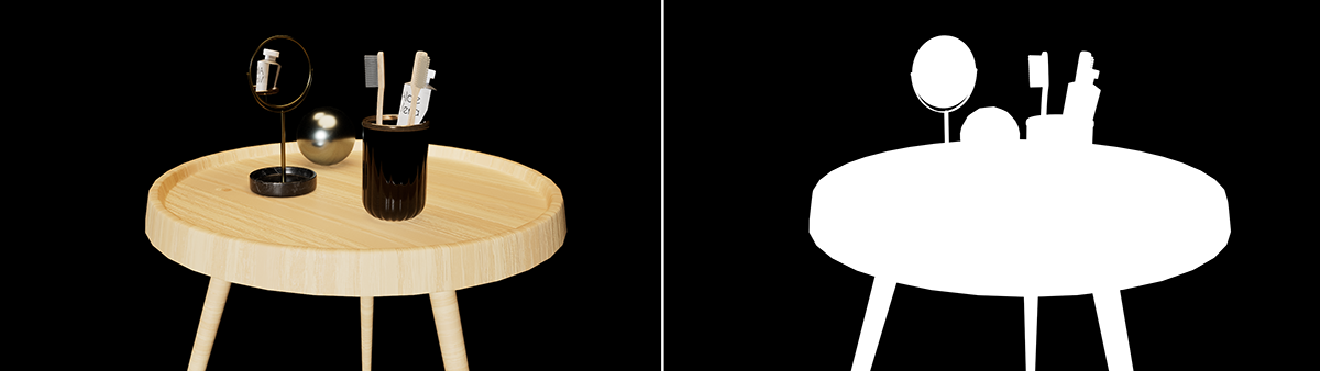
These options are only available when rendering in Frame mode and with Redshift Production. These options enable the calculation and storage of alpha masks. This makes it easier to isolate individual objects in image editing programs. However, these objects must not be surrounded by a Sky or HDRI Environment. Otherwise, these will obscure the entire scene and make it impossible to calculate individual alpha masks.
The Alpha Channel option will render a black and white mask of the scene, using white for the objects and black for the void space in the rendering (see Figure 9). This Alpha Channel is automatically added to the image file if the selected Format allows it. Formats such as TIFF or PSD allow additional channels to be stored within the file. This is not possible with other formats, such as JPEG or PNG. If you still want to use alpha masks with these formats, the Separate Alpha option is available. This creates and saves a second file alongside the actual rendering, which then only contains the alpha mask.
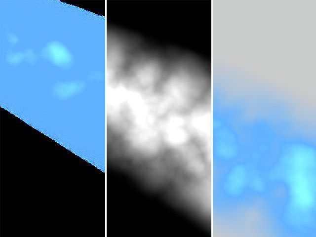
The Straight Alpha option is only relevant for rendering objects that do not have sharply defined outer edges or that use volume-dependent transparency. Think, for example, of smoke or a cloud (see Figure 10). A simple alpha mask would not be accurate enough for such objects, as it may also contain mixed colors from the background in the transparent areas.
Start the Rendering
After you configured the render settings, just hit the Render Frame or Render Storyboard button to start the rendering process. When rendering a Storyboard mode, several frames are automatically calculated one after the other and—depending on the selected file format—saved individually or as a video file after rendering is complete.
Once rendering is complete, a dialog box appears, allowing you to jump directly to the file location using the Locate Image button. Otherwise, simply close the dialog box by clicking OK.
If you do not want to wait for the rendering to finish, you can also use the Stop Rendering button, which appears instead of the Render Frame or Render Storyboard buttons, to cancel a rendering that is still in progress.