Working with Materials
Materials give objects a natural-looking surface. The properties of materials include, for example, the surface color, transparency, and gloss behavior of a surface. The material system uses a physics-based node system that automatically replicates the natural and realistic behavior of real materials such as metal, glass, or wood.
Quick Navigation
- Your Architectural Materials in Maxon Redshift
- Maxon Redshift Material Overview
- Searching for the right Material
- Applying a Material
- Editing a Material
- The Material Projection
- The Material Assignments
Your Architectural Materials in Maxon Redshift
When opening the Maxon Redshift viewer, all the already assigned materials from your architectural application are converted to Maxon Redshift materials and stored in the viewer as read-only. Therefore, it is not possible to edit the converted architectural material directly within Maxon Redshift. In any case, it remains exactly as it was defined in your architectural application.
However, these architectural materials can be unlocked for editing by creating a copy within Maxon Redshift. In this case, the existing material on the corresponding objects is automatically overwritten by its copy. Further information about Material Editing can be found in this section.
A second option is to use a new Maxon Redshift material from the Library Browser and then overwrite the existing material from your architectural application with it. The following sections of this page describe how to access new materials from the Library Browser and assign them to objects.
In both cases, however, the overwriting material newly used on the object can also be deleted again. The originally assigned material will then reappear.
In addition, the following conditions apply:
-
All objects with the same material will automatically get the new mapping. If there are multiple objects with the same material or texture assigned in your architectural application, upon overriding one of them in the Maxon Redshift viewer, all the other models will get the new material in the Maxon Redshift viewer as well.
-
The Redshift materials are not transferred back to your architectural application. It means, that if you assigned a green color to a wall in your architectural tool and then override it with a red material in Maxon Redshift, the visual representation in your architectural app will still show the wall in green.
-
In Maxon Redshift, it is not possible to assign different materials to objects if these objects have all been assigned the same material in your architectural application.
-
If there are two objects with the same texture coming from your architectural app and a new material mapping in Maxon Redshift, then assigning another texture in your architectural app to one of them will result in this object changing its material in the Maxon Redshift viewer to the imported material or its corresponding override (if it already exists).
-
For Revit users: Revit's per-face material assignment is fully supported.
Maxon Redshift Material Overview
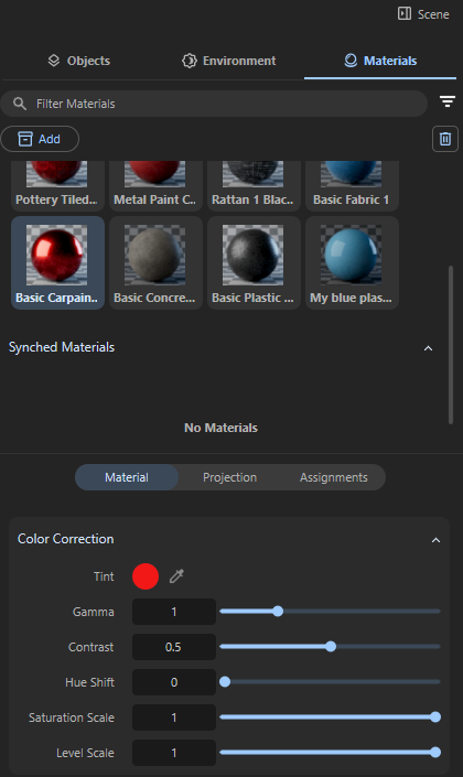
Much of the work has already been done for you, as hundreds of finished materials are already available and can be accessed directly via the Add button in the Scene/Materials section (see Figure 1 below, accessible in the Stage layout).
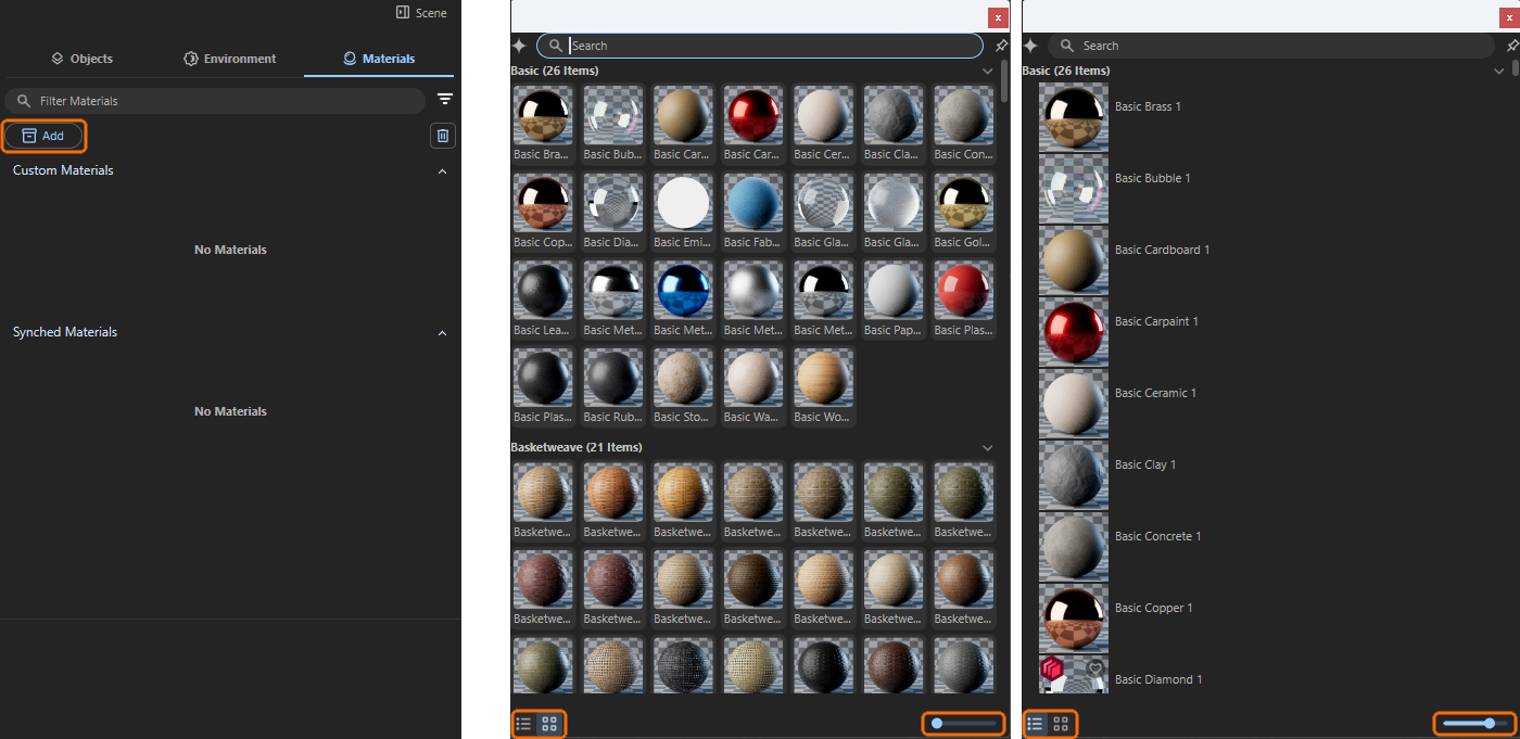
In order to find the right material for a project despite this large number of materials, all materials have been organized into different groups and can also be listed individually with a preview image. There is a mode in which these image tiles are given the maximum amount of space and a mode in which the material entries are displayed as a list (see Figure 1). This leaves more space for the descriptive text for each material, which is displayed next to the material preview. In both modes, which can be switched using two icons at the bottom of the browser window, an additional scaling slider is available, which can be used to individually adjust the area for each material preview (see markings in Figure 1).
Searching for the right Material
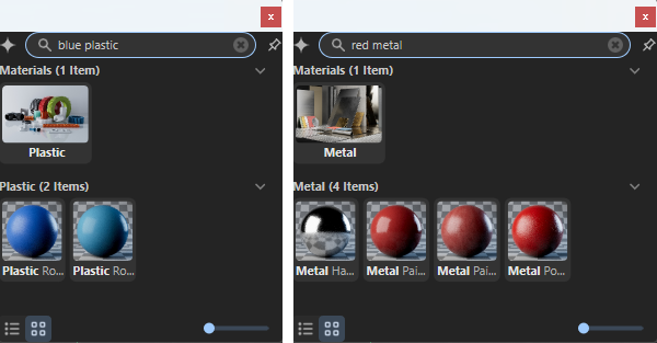
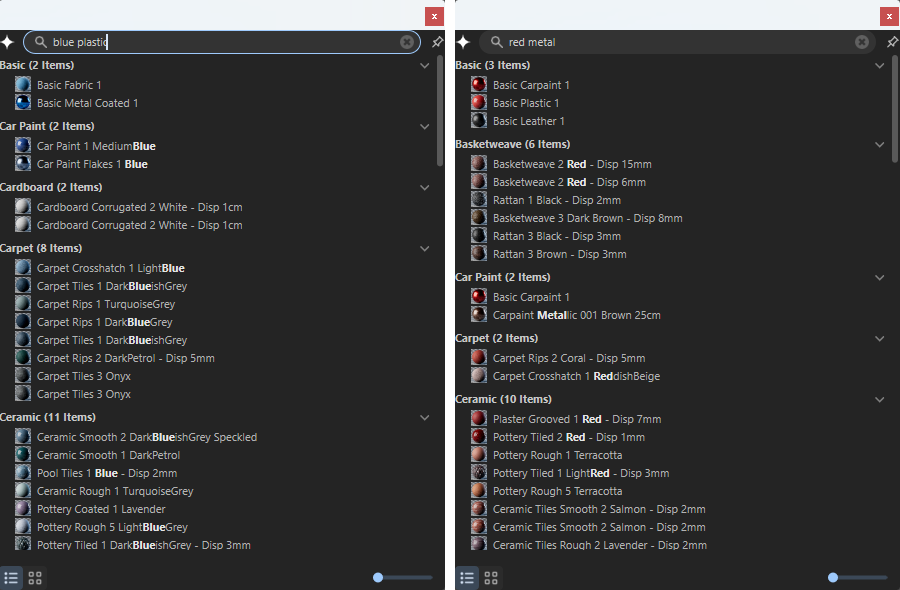
In addition to these material selection options, there is also a search field in the header of the browser. All materials have been assigned descriptive names and keywords so that you can easily search for “metal”, for example. Logical combinations are often possible, such as “blue plastic.”
Even more natural search results can be achieved by using AI-supported search (Artificial Intelligence). This automatically filters materials based on their appearance. A search for a red material, for example, can also return search results that contain surfaces with a slight purple or orange tint. This gives you a wider selection of materials similar to your search term.
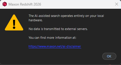
You can activate this AI-supported search by clicking on the star icon to the left of the search field. An information dialog box will appear, confirming that although the AI analyzes the material data and any linked textures, no data will leave your computer (see Figure 3). Processing is therefore carried out exclusively on your local computer (find out more about the options available in the Asset Library Browser here).
After this activation, the search results for otherwise identical search terms are much broader, as the following Figure 4 demonstrates. For example, colors in similar materials are also found automatically. In any case, you will always find the most relevant search results at the top of the browser. The greater the deviation of a material from the search term, the further down the list of search results it will appear.
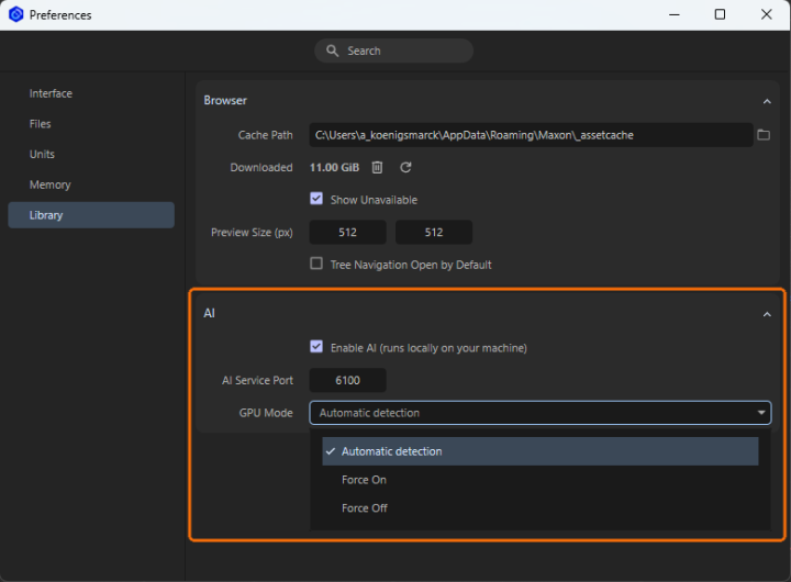
If you like to work with the AI Search by default, you can activate and configure it in the Preferences (see Figure 5). As it is capable of using the GPU, you can configure an automatic detection of your Hardware or force it to use the GPU always or never use the GPU (CPU calculations are slower most of the time).
As the search functionality is also available to filter the other assets in the Library Browser, AI Search can be beneficial not only for materials.
Applying a Material
In order for objects to inherit the properties of materials, the materials must be assigned. This can be done very easily by dragging and dropping them directly from the Materials list onto the corresponding object in the Redshift viewport. The following video demonstrates this process. It also shows that any existing materials on the object will be automatically overwritten.
As per-face material assignment is supported for Revit users, be sure to drag the new material directly to the region where is should be applied.
An alternative option is to use the Material Sampler Tool. This allows you to copy materials already assigned in the scene to other objects, as shown in the following video. To do this, click on the object whose material you want to sample with the active Material Sampler and then Shift-click on the object that you want to apply the sampled material to.
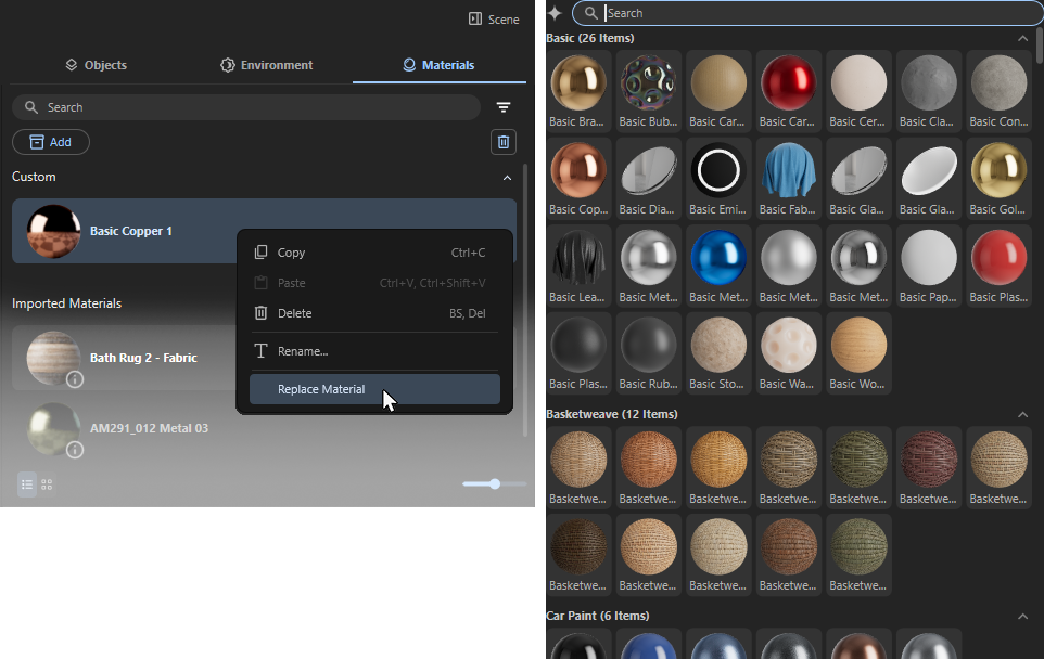
Finally, Custom Materials that have already been assigned can also be replaced with new materials. To do this, right-click on the corresponding Custom Material and then select Replace Material from the context menu. The material category of the Library Browser will open. Select the desired material by double-clicking on it. This will automatically replace the original Custom material on the corresponding objects in the scene.
Newly assigned materials are automatically applied to all objects that have the material being replaced.
For example: All of your window panes have already been assigned the same generic glass material in your architectural software. As soon as you drag one of the optimized glass materials in Maxon Redshift onto one of these window pane objects, all other objects in the scene that used the same generic glass material will automatically adopt the new glass material as well.
Redshift materials projected onto Revit objects via UV mapping are currently being calculated incorrectly in terms of size. Until this issue is resolved, please use Tri-Planar Mapping for Redshift materials instead. There, you can customize the material size as needed.
Editing a Material
There are two categories of materials to consider: materials imported via synchronization with your architectural tool and Custom Materials added to the scene as assets from the Library Browser. The latter can be edited directly, as explained in the following section.
Imported Materials are locked for editing in Maxon Redshift for Archviz, but we can work around this restriction. To do this, you will find an Edit button on Imported Materials when you move the mouse pointer over them in the Materials Manager. Clicking on it creates a new Custom Material that inherits the properties of the Imported Material and is automatically assigned to the same objects as an overwrite material. This new material copy can then be edited, for example, in its color properties. If the material copy is removed, for example, by right-clicking on it and selecting Delete, the original Imported Material is automatically displayed on the objects again. The video below demonstrates this workflow.
Material Parameters
Even if your desired material cannot be found directly, this is of course not a problem. Simply select a material that looks at least similar and then edit it as desired. Many materials already offer a simple dialog box that allows you to adjust colors and contrasts directly.
Start by selecting a similar material. Pay particular attention to the desired gloss behavior or transparency, as these properties remain unchanged. In most cases, the color, saturation, and brightness of a material can be customized.
Color Correction
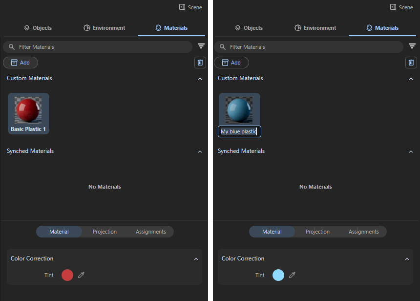
As documented on the left side of Figure 6 you can see, that the chosen plastic material offers a Tint input in the lower Material category of the Scene Manager. Clicking on that circular color field brings up the Color Chooser (described here in detail). Alternatively, you can click on the eyedropper next to the color field to select a color value directly from any point on the screen.
Just adjust the color there to your liking and close the Color Chooser afterwards. Then double-click on the material name below the material preview sphere and enter the desired new name for the customized material (see right side of Figure 6). The customized material is now ready for use. The original material is retained and can still be accessed via the Add button or by searching for it.
Other materials even offer more settings, such as the one in Figure 7.
In addition to the Tint color field already discussed, which allows you to make any changes to the base color, the following settings are also available for some of the materials. Most of these values are settings that are already familiar from image editing. The effect of a setting can depend on the color value that is fed in. For example, the Gamma value changes the mid-tones of a color spectrum more than particularly light or dark colors. In the context of our materials, this is nevertheless relevant, as materials can also contain colored patterns (such as wood grain), which can then be adjusted accordingly using these settings:
-
Gamma: This value refers to a nonlinear adjustment applied to the brightness or luminance of the colors. Its main function is to control how the mid-tones of a spectrum of colors appear without drastically changing the darkest shadows or brightest highlights. In general:
- Gamma = 1.0: All Colors remain unchanged (neutral setting)
- Gamma < 1.0: Mid-tones get brighter
- Gamma > 1.0: Mid-tones get darker
-
Contrast: This controls the difference in luminance or color between the lightest and darkest parts of a given color spectrum. Its main function is to adjust how much separation there is between tones, which affects the overall visual impact. Increasing Contrast makes dark areas darker and bright areas brighter, while decreasing Contrast reduces this difference of colors, making the materials color variations look flatter.
- Contrast = 0.5: All Colors remain unchanged (neutral setting)
- Contrast < 0.5: Reduced separation between light and dark colors; color variations get weaker and appear more washed out.
- Contrast > 0.5: Stronger separation between light and dark colors; color variations looks vivid and sharp.
-
Hue Shift: This allows you to rotate the color angle of the material colors. To understand how this works, take a look at the explanations for the Color Chooser, specifically the Color Wheel. This value can be used to recolor a material without having to change the base color (Tint). Hue Shift 0 allows you to return to the color values originally specified in the material at any time.
-
Saturation Scale: This allows you to adjust the color saturation without changing the hue or brightness of a color.
- Saturation Scale = 1.0: All Colors remain unchanged (neutral setting)
- Saturation Scale < 1.0: Reduction of the original color saturation. With smaller values, the colors only appear as gray values.
-
Level Scale: This value scales the brightness of the color, while keeping hue and saturation unchanged:
- Level Scale = 1.0: All Colors remain unchanged (neutral setting)
- Level Scale < 1.0: Colors get darker
- Level Scale > 1.0: Colors get brighter
Displacement Settings
Some materials use a displacement component that can be used to display unevenness and larger deformations on an otherwise smooth surface. This is helpful, for example, for displaying roughly masonry stone walls or for close-ups, e.g., of pebbles or asphalt. If you have enabled Parallax Mapping in the viewport or for rendering, its intensity is also affected by Displacement Scale.
The Material Projection
In this section, you can specify how the material is applied to objects.
The Projection Group
Here you can set the rotation, size, and repeat rate of the material. In addition, there are two different Projection methods available for applying the material to surfaces, depending on whether your object has suitable UV coordinates or not.
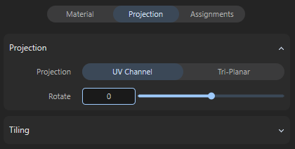
Projection Mode
There are two different options for projecting the material onto the surfaces:
-
UV Channel: If available, the UV coordinates that the object already has. These UV coordinates can be used to individually define the direction, scaling, and position of a material on the surface. However, the UV coordinates must have been assigned and edited beforehand and can only be modified to a limited extent in this mode, e.g., to adjust the rotation or size of the material. If there are no UV coordinates on the object that are suitable for the desired material assignment, this can be compensated for by switching to Tri-Planar.
-
Tri-Planar: In this mode, no UV coordinates are required for the objects, or they are ignored. Instead, the material is projected onto the surface of the objects simultaneously along the three typical object axes X, Y, and Z. This technique often allows for high-quality material assignment even when no UV coordinates are available.
The following illustration clarifies the principle. The colored areas indicate the material that is projected onto the object along the X, Y, and Z directions. The different areas of the object are captured by this projection according to their inclination to these three main planes.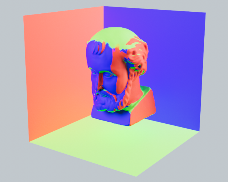
Rotate Value
Here, you can specify an angle by which the material should be rotated. For example, the grain direction of wooden planks can be rotated to match the object.
Size Value
This setting is only available for the Tri-Planar setting and determines the size of the texture projections. Smaller values will then result in more repetitions of the material on the surface by default.
The Tiling Group
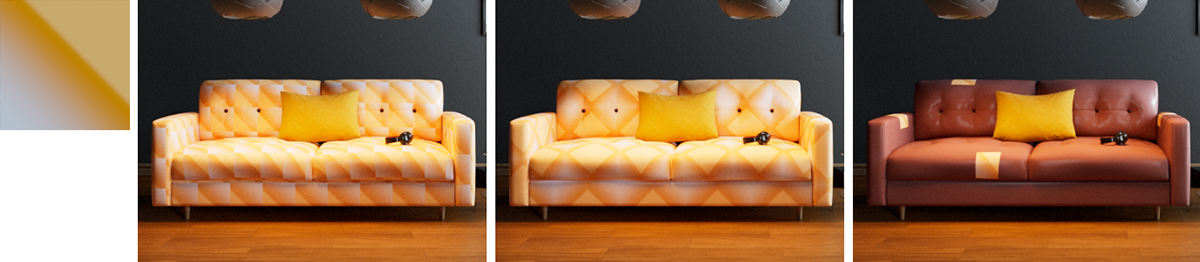
Tiles U/V Values
If the material contains shaders or textures, these values can be used to indirectly adjust their size within a material tile. Values above 1 reduce the size of the textures, while values below 1 enlarge them. The letters U and V stand for the horizontal and vertical directions within the texture tile. With Tiles U = 2, the material is compressed sideways to half its size. This means that two copies of the material fit into one material tile.
The example above in the video demonstrates the effect of different texture scales within the material tiles. In each case, Wrap U und Wrap V is configured to Repeat the material, which means that the material is automatically repeated endlessly to fill the surface.
Offset Values
Imagine the image elements within the material as if they were painted on a tile. Internally, such a texture tile always has an edge length of 1 in the horizontal and vertical directions (corresponding to the width and height of the textures in the material). Using these Offset values, this texture tile can now be moved horizontally (first value) and vertically (second value). With the value pair 0.5 and 0.0 for example, the image elements in the material would be moved horizontally by half their width.
Wrap U/V Values
Whenever a material tile is smaller than the surface to be covered with the material, automatic repetition of the material tile can be activated. This effect is controlled by these settings:
-
Repeat: This is the default setting and causes the material to be automatically repeated in the appropriate direction to cover the entire assigned object. The effect is comparable to laying floor tiles. Each added material tile is identical to the original tile and is only shifted in a U or V direction.
-
Mirror: In this mode, copies of the original material tile are also automatically added in the U or V direction. However, every second tile is mirrored in the corresponding direction. This is helpful if, for example, the material has distinctive patterns but the edge structures are not identical, i.e., if the left edge of the material has different colors than the right edge. If the material tiles were simply placed next to or on top of each other, the transition from one tile to the next would be immediately noticeable. By mirroring the tiles alternately, this transition between adjacent tiles can at least be softened.
-
Clip: It is not always helpful for a material to repeat endlessly and cover the entire surface. Think, for example, of applying a sticker or logo to an object. These elements should only be visible once on the surface and not multiple times next to or on top of each other. In these cases, select Clip so that the material is not repeated in the corresponding direction. The position of the non-tiled and therefore only once visible material can be influenced by the Offset values.
Flip U/V Options
These options allow you to mirror the UV coordinates of the surface used for material assignment separately for the U and V directions. This can be helpful, for example, if you are using materials with text elements or logos and these appear mirrored on the surface. Please note that mirroring the UV coordinates may also require the Offset values to be readjusted.
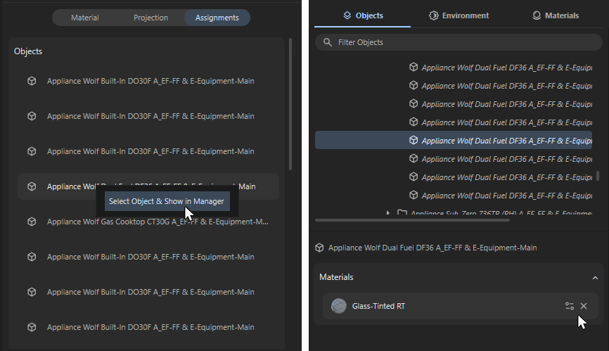
The Material Assignments
This lists the names of all objects to which the material has been assigned. Right-clicking on individual entries opens a context menu that allows you to select the corresponding object, making it easier to find in the viewport or object list. As shown in the right-hand side of the figure below, selected objects automatically display the materials used with them in the lower Attribute Manager. Moving the mouse pointer over these entries displays icons that can be used to call up settings such as color correction or projection, or to remove the material from the surface.