Options
Level of Detail
Defines the LOD (level of detail), i.e., how detailed certain objects will be displayed in the Viewports. These settings set the otherwise steplessly adjustable Level of Detail setting in the Scene Settings.
Level Of Detail
25%
50%
The setting affects the level of detail (LOD) shown for objects that support LOD. The lower the setting, the faster the display.
Here you can define for each view if the LOD defined in the respective settings (e.g., Subdivision Surfaces) should be used for rendering.
Enable this option if you want a stereoscopic display in the Viewport. Details regarding stereoscopy can be found here. Note that a stereoscopic depiction is only possible in the Parallel or Perspective views.
This function can be used to hide or show the dark bands for safe frames at the Viewport edges (see Safe Frames).
Here the display of colors, shaders, etc. in the Viewport can be turned off, in consideration of linear workflow.
If you want to use additional effects for the current Viewport you can define here if these should be displayed.
The more complex the scene the slower the refresh rate will be.
Note that you can also define at material level which channels should be displayed (Viewport channel).
 Left: Viewport display. Right: Rendered image.
This is where you can enable the display of the Noise Shader for higher quality (HQ)..
Use this setting to define whether or not post effects should be displayed. Note that there is only limited support for Cinema 4D post effects (e.g., the Cartoon Renderer post effect; enabled Color, Lighting, Step options). This option is primarily designed for plug-ins that use post effects.
Enable this option if you want Magic Bullet Looks to be applied directly in the Viewport. The Magic Bullet Looks post effect must also be enabled in the Render Settings menu.
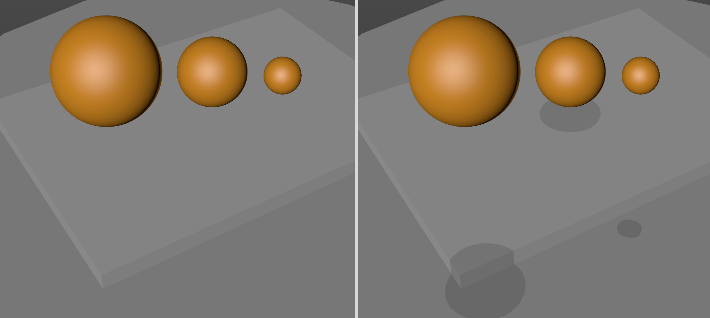 Note how you can intuitively "read" the depth information (right)by activating the Shadow Hinting option.
For selected objects - including Child objects - Shadow Hinting casts a shadow downwards. The effect is similar to shadows generated by an Infinite light source.
This effect helps you "read" the scene with regard to depth. You can better approximate the height and distance of objects from one another.
Shadow Hinting can, of course, not compete with a real shadow, which means that, for example, an object will not receive shadows. Imaging 2 objects lying on top of one another: the selected object would cast shadows on both surfaces. Also, the shadow resolution will suffer in conjunction with large distances and small objects: the shadows will be less precise or even not visible.
Use this setting to define whether or not shadows should be displayed.
Use this setting to define whether or not transparency should be displayed in high quality. Note that antialiasing does not work in the Viewport in this mode.
Defines whether or not reflections should be displayed. Details can be found here
Defines whether or not an Ambient Occlusion approximation should be rendered in the Viewport. See also SSAO.
Defines whether or not tessellation should be displayed for respective objects in the Viewport. See also Tessellation.
Defines if a simulated depth of field should be displayed. For details see Depth of Field.
This option can be used to enable or disable the display of textures (bitmaps/shaders) in the Viewport.
This option can also be used to turn the material display on or off.
The material display can be turned on or off for each object individually. To do so, create a Display tag in the Object Manager (Object Manager: Render Tags / Display tag).
Objects assigned to a layer can be displayed in the editor view in the color of that respective layer. This lets you quickly see which objects have been assigned to which layer.
Use this option to toggle backface culling on or off when in Lines mode. Backface culling can speed up the display and make the scene easier to understand and edit. With backface culling, all concealed surfaces are hidden. A backface is a surface that points away from the camera.
Cinema 4D knows the direction of a surface by looking at its surface normal. If the surface normal points towards the camera, the surface is a front face. If the surface normal points away from the camera, the surface is a backface and is not drawn when Backface Culling is enabled. Figure 1 demonstrates the backface principle.
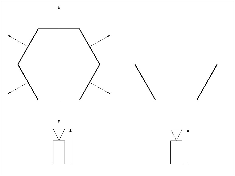
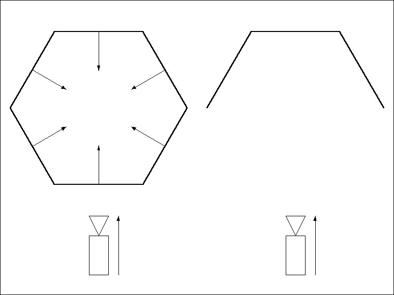
By convention, the Normals should point outwards from their surfaces, as in Figure 1. Objects with Normals that point inwards may cause display errors. To remedy, reverse the Normals, as illustrated in Figure 2, using the Reverse Normals command (Functions menu).
The following picture demonstrates how backface culling applied to a sphere.
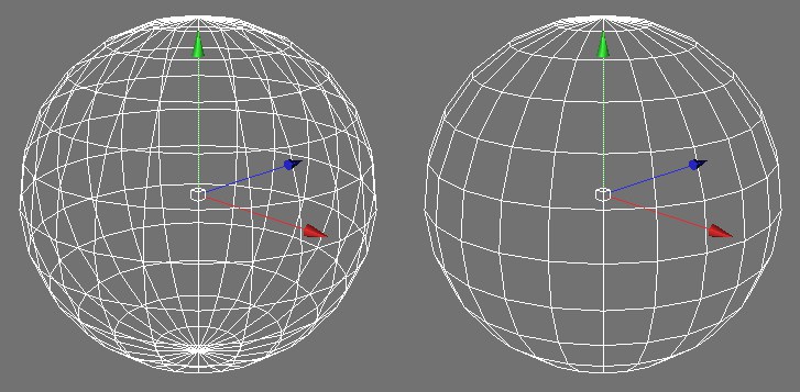 Backface Culling disabled (left) and enabled (right).
To activate the X-ray effect, enable this option. If the active object is an object (applies to all that are made up of polygons or generate polygons), it will become semi-transparent so that you can see its concealed points and edges. This is particularly helpful with polygon-based modeling, since it enables you to see concealed components in the Gouraud shading and quick shading modes.
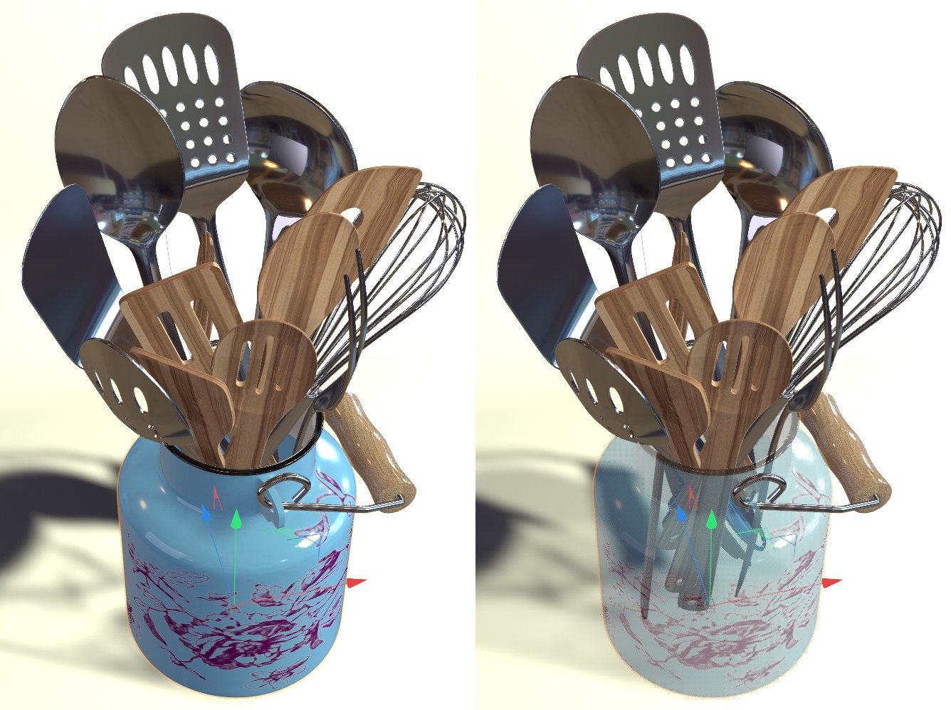 Left: X-ray mode off. Right: X-ray mode on.
When in Polygon mode, the display of Polygon Normals can be turned on or off here.
When in Use Point, Use Edge or Use Polygon mode, this option can be used to enable or disable Vertex Normals (see also Vertex Normals).
Internally, all object points and polygons are numbered, as you already know from the respective column in the Structure Manager.
Enable/disable this option to display polygon or point numbers of selected objects directly in the Viewport.
Depending on the selected point, edge or polygon mode, different elements will be displayed (e.g, edge start and end points in Use Edge mode) or omitted (e.g., the point indeces in Use Polygon mode). Point indeces will always be blue, polygon indeces will always be red.
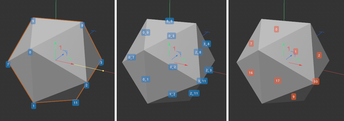 On the far lift is a depiction of point indeces in Use Point mode; at center the paired point indeces in Use Edge mode; point indeces are shown on the right..
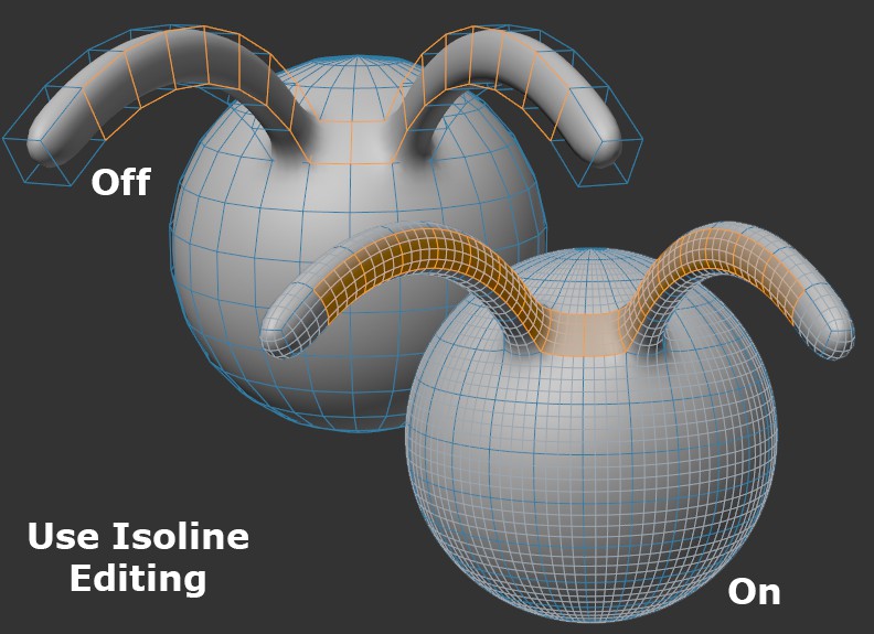
If enabled, all Subdivision Surfaces cage object elements (points, edges, polygons) will be projected onto the smoothed Subdivision Surfaces object so that these elements can be selected directly on the smoothed object.
If this option is enabled, the objects will use the display mode defined in their Display tags (if present). Objects without a Display tag will continue to use the viewport's shading mode.
If it bothers you if the workplane is displayed in front of a given object: this option can then be disabled and the workplane will never be displayed in front of an object from the view of the camera - it will be hidden (this can be defined permanently in the Preferences menu under Viewport Display).
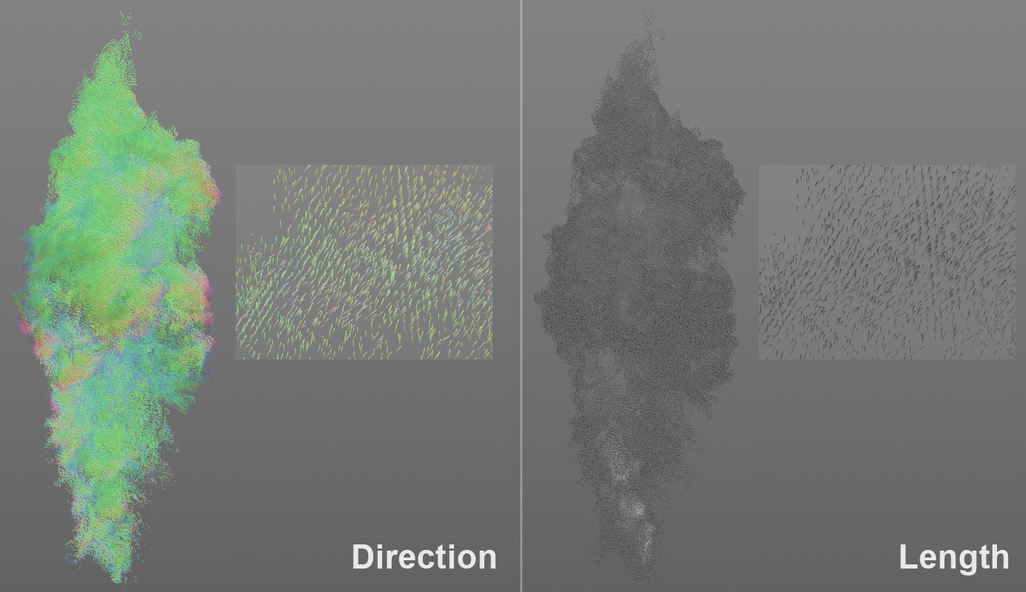
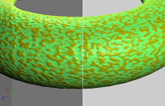
For Volume Vectors, you can define here how they should be displayed in the viewport.
- Direction: The vectors will be colored according to their direction
- Length: The vector length will be used as a visual measure for the vector value (strength): black for smaller, white for greater strength.
In the image above you see the distribution of velocity of the gasses within a fire as volume vectors. In Direction mode you see mostly green vectors and the gasses move primarily upwards along the Y axis. In Length mode, the vectors are colored white near the flames - here especially high velocities take place.
The type of display can also be defined at object level in the Display tag.