Scene Settings
Units in general
In earlier Cinema 4D versions (< R 12) there were no real units. You could define any mm, m or km there, but none of this made any difference to C4D. There was always an appendage without a function in the respective value field.
This is now different: 1m now has 100 centimeter and 1 kilometer 1000 meter etc., i.e. if you change the Display setting for units in the Preferences from Meters to Centimeters, for example, a 2m wide cube will then be displayed as 200cm. The values are therefore converted if the Show Units option is activated.
What is that good for? In combination with the double (internal) precision (which has been increased from 32-bit to 64-bit as of R 12), oddities caused by rounding errors are now a thing of the past. This means that you can first model 2 small dust grains in the millimeter range in one and the same scene, then switch to kilometer and place a gymnasium around the dust grains. Cinema 4D now handles this perfectly.
It is now also possible to load objects modeled in mm into a scene where the objects have sizes of hundreds of meters, i.e. if you copy objects from one scene to the next, the conversion happens automatically.
You can adjust units here within Cinema 4D:
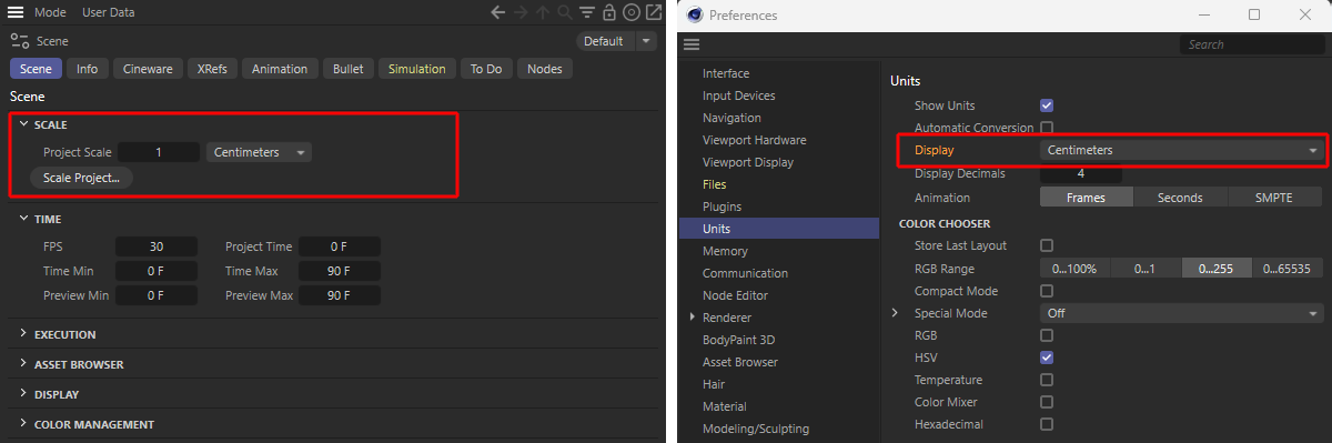 Units can be set anywhere here. Scene Settings on the left, Cinema 4D Preferences on the right.
- In the program Preferences: This setting has no effect on any scene events. This only changes the units displayed in the corresponding fields. The values are converted in the process. If it previously read "3 cm" and you switch to Meters, the field will then read "0.03 m" (or 0.033 yd, for example). The following setting is more important:
- In the Scene Settings: Depending on what you set here, the scaling of the scene actually changes. A previously 200cm wide cube (Project Scale Centimeters) is actually 200m wide when switching to Meters.
Project Scale
This parameter is the most important unit parameter. It determines how the numerical value stored in the file is actually interpreted. 3 meters, 3 kilometers or rather 3 yards? An empty, new scene always opens with the default Scene Settings. This is the right time to consider the scale at which you want to model. Simply use the real, actual sizes of the object to be displayed as a guide. In the case of a house, for example, this is Meters, in the case of the innards of a watch Millimeters, in the case of a mountain range perhaps Kilometers.
The default factor additionally scales the scene by any value.
You can change the Project Scale at any time if you are working in very large and very small dimensions at the same time.
![]()
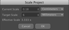
When loading old scenes or objects imported from third-party programs, these often do not have the correct length units or none at all. To bring such scenes to the correct scale, there is this command.
Imagine you have imported an IGES hexagon head screw with unknown scaling. You know that it is an M6 screw. The project is set to the default 'Centimeters'. You now only need to select one point on each of the opposite sides of the hexagon and determine the distance between the two (the Coordinate Manager provides information).
Assuming that the two points are 0.18 cm apart, you only need to enter the following values here and the scene will be scaled correctly:
Use this value to determine the frame rate for the current project. Cinema 4D uses this specification to calculate all animations in the scene.
Basically, frame rates can be defined in 4 places in Cinema 4D:
- here in the Scene Settings. Cinema 4D calculates all animations internally with this frame rate. This is the basic frame rate; all the frame rates mentioned below are based on this frame rate by default, i.e. they use exactly this frame rate.
- in the Render Settings. Cinema 4D renders at this frame rate.
- in the Animate menu (see here). Cinema 4D plays animations in the view at this frame rate. This can be used to play animations faster or slower as a test.
- in the Picture Viewer. The Picture Viewer plays loaded/rendered image/video sequences at this frame rate.
By default, all 4 of these are set to 25 (e.g. Germany) or 30 images (e.g. USA) per second. In most cases, it is advisable to set these 3 to an identical value.
This is the current time that is defined by the time slider of the animation palette.
This is where you define the start time of animation tracks. This value can also be negative, e.g., to start a particle system before starting the calculation of a movie.
This is used to define the end time of animation tracks.
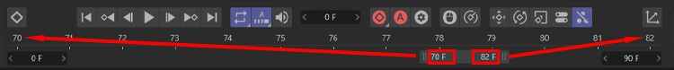
These are the two points in time that limit the displayed preview area. These can also be changed by double-clicking on the positions marked above in the power slider.
This default value influences the display of all objects in the current scene, for which you can select a specific level of detail. Such objects include all primitives, metaballs and all generators.
Regardless of the Level of Detail set in the individual object, you can further reduce the level of detail here.
If the value is set to 100%, all objects appear in full display (according to the values defined in the object properties).
If the value is set to 50%, for example, all objects in a scene are only drawn with half of all lines in the view window.
Regardless of the value defined for the Level of Detail, the value defined in the Render settings is used when rendering in the Viewport.
These 4 options do exactly the same as if you switch them via the options of the same name in the Mode / Execute menu of the main menu. Details on the functionality can be found here.
If you want to switch off the Motion System temporarily, you can do this here or via the option of the same name here: Main menu: menu.
Here you have the option of setting a color for all objects without explicitly assigning a material.
This and the next setting relate to the functionality of the Watch Folders. Details can be found here.
With this option, you can define at project level whether the existing "tex" folders from the scene storage location should be defined as monitoring folders. This path can be adjusted with the following setting.
By default, the "tex" folder is set at the scene storage location. However, you can also define any other path here either as a relative path or select a path using the folder icon on the right. If possible - the folder is located on the same drive as the saved scene file - a relative path is then automatically set here (see also File for some details on relative paths).
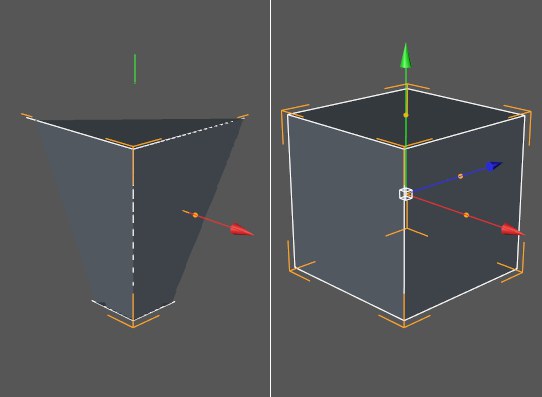 If you get incorrect displays as shown on the left, it helps to set a different clipping area.
Due to the possibility of working simultaneously in very large dimensions (e.g., kilometers) and also in very small dimensions (e.g., nanometers), the view display (and only this, rendered it works perfectly anyway) is somewhat overstrained (the Z-buffer has only a limited resolution and at some point can no longer distinguish which polygons are behind each other, which results in poor display quality).
In this case, you have the option of setting a clipping area here. Outside this clipping area (calculated in the direction of camera view), the display is cut off. Within the clipping area, the ratio of Near to Far should not be too large, the display is then always correct.
Select a suitable area from the selection menu or set a manual area using Near and Far.
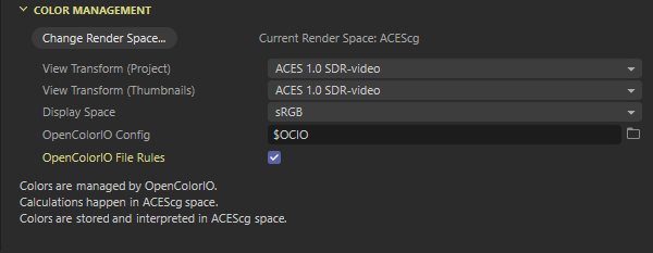 The Color Management settings in the Scene Settings.
The settings in this section define how imported colors are interpreted and rendered colors are displayed or passed on in an image file. In general, Color Management deals with the fundamental problem that we need the most precise color and brightness values possible during rendering, but the color values set or textures used in materials often only use a small part of this color space. In addition, the human eye or the display devices can only perceive or display a very small part of the mathematically possible color values. On the other hand, further processing of the rendered images in post-production benefits from the highest possible brightness and color density.
Colors often have to be converted from smaller color spaces (e.g., color values set via color pickers or loaded JPG textures) into larger color spaces for rendering, while the render results have to be converted from these larger color spaces back into smaller ones, e.g., for displaying material preview images or in the Picture Viewer. After all, even monitors with a high dynamic range cannot fully display the huge color spaces used for rendering.
An implementation of the OpenColorIO system (OCIO), in which the ACES color spaces are also available, is available by default. This enables comprehensive color management across different programs. With version 2025.0, its use has been further simplified so that you often don't have to worry about anything else.
Please note, however, that older project files may still have been configured with other color spaces and the linear workflow. In such cases, the Color Mangement settings appear partially greyed out. The old Color Mangement is then retained for these scenes in order to be able to continue rendering comparable results. However, the Change Render Space... button can also be used to convert such older scenes to the more modern ACEScg color space, for example.
Here you will find information on the older Linear workflow. The corresponding 'Simple' Color Mangement of earlier versions is documented here.
The theory of Color Mangement is quite sophisticated overall and is subject to constant further development. If you would like to find out more about the basics, you can find an overview here. The following explanations deal more with the specific settings and modes as they are made available to you here in Cinema 4D.
The large color space used for rendering makes sense not only for the accuracy of the image calculation, but above all for post-processing. The more color information and gradations there are in the brightness, the more intensively color and brightness transitions can be edited in post-production without tearing or other artifacts. Therefore, only formats that can handle the high bit depths and floating point values, but at the same time can also contain additional layers, for example, should be used to save the renderings. Special HDRI formats such as OpenEXR are often used for this purpose.
Change Render Space...
In general, it always makes sense to use the largest possible color space for rendering so that, for example, extreme lighting conditions in the scene do not result in visible gradations in brightness gradients (banding) or the clipping of color values. Even if these problems are not immediately visible in the rendered image, it can make subsequent recoloring or brightening in post-production impossible, for example, as tearing will occur in these areas.
It is also helpful for the rendering that a gamma weighting of the brightness is not already calculated. This would often mean that contrasts would be enhanced, which would also make post-processing more complicated and change the mathematically precise color values. For this reason, color spaces that use colors and their brightness in a mathematically exact and linear way are suitable for rendering. For this reason, Cinema 4D only offers color spaces for rendering that meet these criteria as standard.
The currently-selected color space is always displayed to the right of the button.
Current Render Space
First, the color space currently being used for rendering is displayed in the Change Render Space dialog under Current Render Space. For new projects, this is always ACEScg, as this color space only uses positive values for color components and can therefore be processed by all image and video programs without any problems. This color space is also large enough for most applications. Only the ACES2065-1 Color Space is even larger, but can also contain negative values.
When loading older projects, the Legacy mode can also be displayed here, which corresponds to the old Linear workflow (see also the left-hand side of the following image). By changing the New Render Space setting, all color spaces can generally be converted into one another. When switching from larger to smaller color spaces, however, this can also lead to changes in the renderings. However, the textures and colors entered are converted to the selected render color space by default.
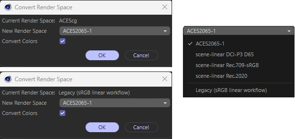 Convert Colors settings for Render Color Space.
New Render Space
If you want to adjust the render color space, e.g., due to specifications from post-production, you can use the New Render Space menu. Below you will find explanations of the different modes and also a graphic that shows the different color spaces schematically.
| Color Space (Gamut) | Description |
|---|---|
| ACES 2065-1 | This ACES Color Space is considered future-proof and represents the most comprehensive color space. However, negative color components may also be included, which not all processing programs can handle. |
| ACEScg | This color space was developed in accordance with ACES 2065-1 in order to overcome the limitations of common post-production applications, as only positive values occur in this color space. At the same time, however, there is still enough space for a large gamut. According to the ACES conventions, this should only be the "in-house" format, as the color space is reduced compared to ACES 2065-1 and is not considered an ACES-compliant storage format. |
| Scene-Linear DCI P3 D65 | This format is closely based on the gamut of typical cinema projectors, with the white point set to daylight. Please inquire which white point is required for delivery, as this could be a lower Kelvin value. This would not play a role in ACES 2065-1 and would not have to be taken into account during production. Current top-class laser projectors can all be viewed at Rec. 2020 (see definition of Scene-Linear Rec. 2020 below). |
| Scene-Linear Rec. 709 - sRGB | This is the standard for HDTV and computer monitors, using integer numbers. It was published in 1993, with the current version BT. 709-6 dates from 2015 and has many variants due to its relationship with sRGB, especially with regard to gamma definitions. The specification as a Scene Linear enables a much simpler exchange here, as all gamma variations and definitions are excluded. Therefore, both are linear and offer the same color space (gamut). In Cinema 4D, both (Scene-Linear Rec. 709 and Scene-Linear sRGB) are used interchangeably, based on linear floating point values. This is not the case when they are down-converted to integers. A linear file format on a float basis is absolutely essential for color fidelity. In this way, the possible color definitions have increased drastically. These are based on values above 1.0, even for colors that would perhaps be below 1.0 in larger color spaces. With proper conversion in post-processing, greater color fidelity is achieved than would ever be possible with integer 8-bit or 16-bit formats in sRGB. |
| Scene-Linear Rec. 2020 | This color space was established in 2012 as the new standard for UHD (Ultra High Definition) and defines a color space that significantly exceeds the sRGB color space and the DCI-P3 color space. Later, UHD, which was incorrectly referred to as 4K (3840 pixels wide), was no longer the only format available in Rec. 2020 was defined. The second format is 7680 pixels wide and is often referred to as 8K; in either case, a ratio of 16:9 is taken into account. The standard is described as 10- and 12-bit/channel integer, whereby floating point, also known as scene linear, is qualitatively preferable during production. The linear mode of operation enables the entire pipeline to manipulate color values without data being cut off. This helps to avoid restrictions within the pipeline. |
| Legacy (sRGB Linear Workflow) | This mode corresponds to the mode of operation of older Cinema 4D versions (Standard Renderer or Physical Renderer) and does not correspond to the ACES workflow or the color spaces offered by OCIO. In this mode, all entered colors are saved as non-linear sRGB values and then converted to the linear sRGB color space during rendering. The disadvantage of this principle is that no colors can be used that lie outside the non-linear sRGB color space. |
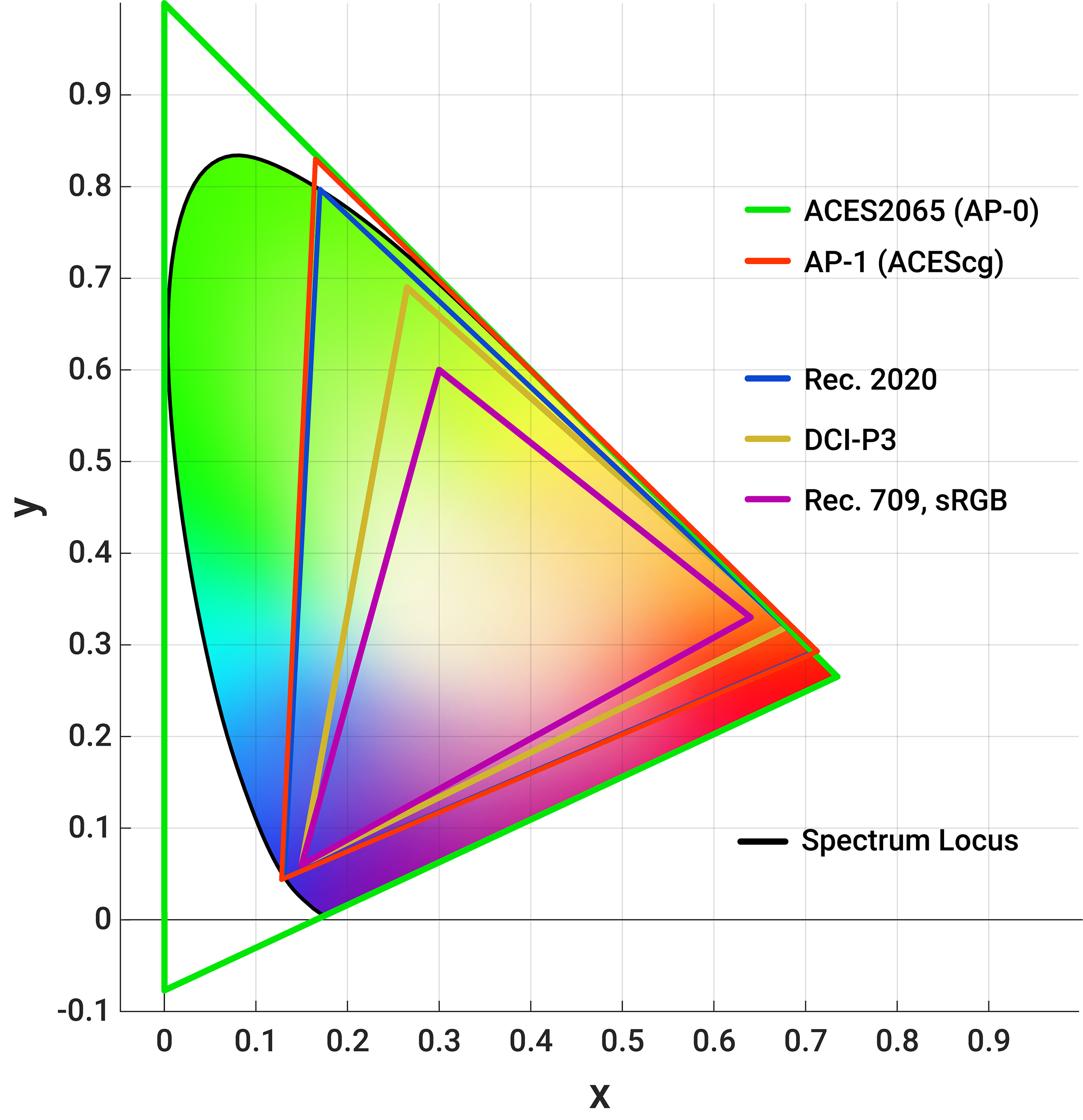 Schematic representation of some ACES color spaces compared to common display device color spaces, such as Rec.709/sRGB. The colors contained in the ACES color spaces go far beyond the colors that can be displayed in sRGB, so the color representation here is only symbolic.
If you switch from one ACES color space to another ACES color space, all color values used in the interface are converted so that they appear as visually unchanged as possible. Images and loaded films that are not in the project's color space are converted accordingly. However, when switching from a larger to a smaller color space, color values may change when rendering again.
Please also note that the Color Mangement system cannot know how colors should be used within a material, for example. Colors and textures that are used in data channels, such as bump, displacement, normal or alpha maps, are also included in this conversion. Example: A color shader in the alpha channel. For this reason, you will also find options for selecting which color space should be used in each case at these points where textures, shaders or colors can be set and loaded. Normal and displacement maps, for example, are often interpreted linearly, whereas color textures are usually available in the sRGB color space with an imprinted gamma.
Convert Colors
If this option is active, all colors used in the scene, e.g., within color selectors or loaded textures, are converted to the new color space. This is the default setting and should only be switched off if you know what you are doing and want to avoid color conversion at all costs. Bear in mind that changing from a larger to a smaller color space can result in a loss of information in the colors if they are in the outer range of the original color space.
Here you will find a number of options that display transformation calculations for color values from the Render Space so that you can view your work in the editor and, for example, the Picture Viewer or Redshift RenderView. The transformations offered are often a type of tonal value correction that converts the often very finely graded or very large color values calculated during rendering into the small and limited display values of your monitor, for example. This can be useful, for example, to set the correct exposure. The Display Space and the selected View Transform (Project) setting together describe the Output Transform.
- ACES 1.0 SDR video is an OCIO display function that is also used under the description 'sRGB monitor (sectional EOTF)'. The abbreviation EOTF stands for the standard term used in color science, "Electro-Optical Transfer Function", and describes the conversion functions between digital color values and the brightness values that can be displayed on a display device. The result is a gamma-based sRGB data set.
- Log (Logarithmic Gamma Curve) is the preferred way for colorists to view and work with content. This results in a reduction of the image contrast, particularly in the dark and light image content, which leads to more visible details.
- With Raw, all color values are displayed unchanged, which can be particularly useful when evaluating individual multi-passes if they are used for data storage (e.g., for masks or a Z-buffer).
- Normally, the display space of a playback device is much smaller than the linear render space. Output colors are therefore corrected via a tone value correction in order to be displayed. You can deactivate this tone value correction by selecting Un-tone-mapped. The color values are then displayed unchanged and are no longer clipped, even if they are outside the Display Space.
You also have the option of switching the display transformation directly in the Picture Viewer if you want to experiment with the various options. However, the Viewport Configuration Settings also offer you options for overwriting the View Transform directly in the 3D views. An individual override can also be carried out in the Redshift Render View. These options can be seen in the following image.
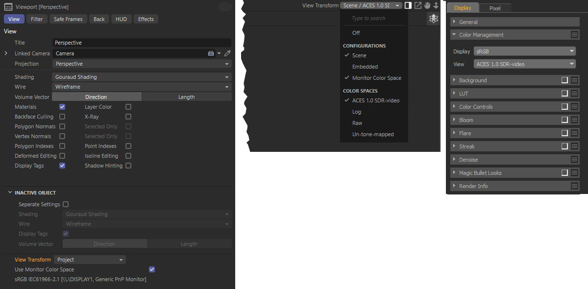 The Display Space can be switched individually for the editor views in the View settings (left) with the View Transform setting. The Picture Viewer (middle image) and the Redshift RenderView (on the right) also offer individual Color Mangement settings for overwriting the transformation of the display or view color space.
The same options are available here as for View Transform (Project) (see above), but these are only used here for the material thumbnails and the preview areas of Nodes.
This setting allows us to define how the color information from the scene-related (rendered) data is interpreted for viewing on a display device (usually your monitor). Currently, sRGB is the only standard. You will therefore not be able to make any changes here.
Here you can link an OCIO configuration file by clicking on the folder icon to the right of the field. However, a corresponding file is already installed together with Cinema 4D, which you can automatically refer to with the abbreviation $(DEFAULT).
Alternatively, you can also define your own environment variable under the abbreviation OCIO and use it to refer to your own file path. You can then access this variable directly via the term $(OCIO) in this field. If $(OCIO) is not defined or cannot be found, $(DEFAULT) or the supplied OCIO configuration file is also used.
Further explanations on creating environment variables can be found here.
This also automatically subjects the color profiles of loaded image files and textures to the rules of the active OCIO configuration file.
Information
In the lower part of the Color Mangement settings, all information is summarized once again, such as which Color Mangement system (e.g., OpenColorIO) is used, which render color space is active and how the colors and textures are interpreted.
- Copy/cut/paste scene objects: If you have opened several scenes and exchange elements between them by copying or cutting and pasting, the Color Mangement of the copied element is automatically converted to the Color Mangement of the target scene. This ensures that uniform Color Mangement is used for all elements in a scene.
- If OpenColorIO is active, standard colors or standard color gradients of objects or materials are automatically interpreted as non-linear sRGB colors and converted to the selected render color space.
- Saved presets for colors or gradients are interpreted correctly for the current Color Mangement. There are therefore no changes to these colors.
- All color selectors offer individual modes for selecting the color space in which a color value should be set. Colors entered are automatically saved and interpreted within the selected render color space and only converted to the display color space for the display of numerical values and colors in the dialogs. If the input color space of a color selector is subsequently switched to a smaller color space, the set color values may be clipped. In most cases, you will use the sRGB Color Space as the input color space for color values.
The Linear Workflow (or far too many gammas)
In a nutshell
In recent years, the principle of Linear Workflow (hereinafter referred to as 'LWF') has almost become a process shrouded in myth that promises miracles. Well, it can't work miracles, but it will help you to produce better images that previously could only be achieved with additional effort or workarounds.
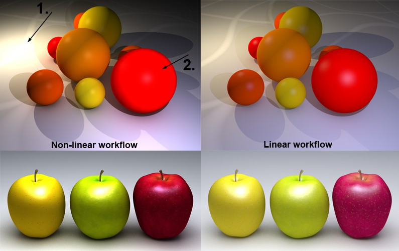 Overexposed areas are reduced.
You can see the effects of the LWF in the illustration above. This scene is illuminated by 2 light sources (inverse square decay). The quality with LWF on the right is dramatically better.
The following advantages can be noted:
- More harmonious light distribution, scene appears brighter overall
- Overexposed areas are reduced
- More natural colors
- In summary: more realistic light distribution (the use of light sources with physically correct inverse square Falloff is also recommended at this point).
Note that all internal Cinema 4D material colors and gradients are also changed directly in the preview. Of course, this can also lead to all sorts of confusion, as simple grayscale gradients, for example, look different than they used to.
The color value of 128,128,128 ( Linear Workflow option deactivated) saved in a regular greyscale gradient at half length changes to approx. 192,192,192) when this option is activated. This behavior is CORRECT!
For those of you who are interested in the background, read the next section; for everyone else, enjoy the more beautiful pictures right now.
Details
The whole issue of gamma values and the associated LWF is due to the simple fact that a renderer calculates internally with linear gamma (= 1), but it is fed a different gamma (usually 2.2, since macOS 10.6 also for Mac users, previously 1.8) as input (textures, shaders etc.), although it also expects gamma = 1.
As a result, the renderer basically calculates "more incorrectly" (in the sense of less physically correct) than it actually should.
If you now cry out: "Oh dear, have I only ever produced sub-optimally for the last 10 years?", the answer is a decisive "yes and no". If the end result is pleasing to the eye, then that's all well and good. However, over time you get used to the peculiarities of a renderer and work around the problem, so to speak. Maybe put a fill light here, change the color there to get the desired result, which might not have been necessary when using an LWF.
This is also the reason why old scenes do not automatically look better if you activate the LWF now. This is because they are designed to work well without LWF.
If you use old, existing, optimized light configurations again and again, you should adapt them when you switch to LWF. However, if you are satisfied with the rendering results, there is of course no reason to only use the LWF.
Why are there actually gamma values?
Monitors, for example, usually have a gamma value of 2.2. If you paint a texture in an image editing program of your choice, this image will be displayed with a gamma of 2.2 and also saved for this purpose. The vast majority of images that you have created yourself or that you find on the Internet have a gamma of 2.2.
Only with this gamma do images look good on an average monitor. This is due to the fact that images with a lower bit depth (8-bit and 16-bit) are stored in such a way that a brightness gradient is displayed that is satisfactory to the human eye. The eye is able to recognize finer gradations in dark image areas than in bright ones.
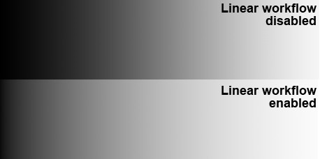
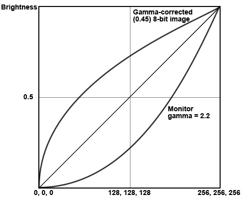 A gamma-corrected 8-bit image with gamma = 0.45 is displayed on a monitor (gamma = 2.2) with a gamma value suitable for the human eye. Eye linear brightness curve.
Renderers on the other hand (including Cinema 4D) work internally with linear gamma gradients (i.e. gamma = 1; this is what the common algorithms want) and also expect this from the things they are fed with (textures, shaders etc.). However, this has not been the case until now. The renderer would like gamma = 1, but gets 2.2. It is logical that deviations from the physically correct result occur.
As soon as the renderer has completed its work, it must reduce the color and brightness of the calculated image (unless it is saved in 32 bits - in which case the gamma adjustment is shifted to a subsequent processing step) and at the same time apply a gamma value (namely 2.2) so that the finished image can be displayed on the monitor in a meaningful way.
How does the LWF fit into the above? Quite simply, as soon as you activate the LWF, all elements required for the rendering process (textures, shaders etc.) are converted so that the renderer sees them with the required linear gamma (=1). After rendering correctly this time - the renderer also produces images with a gamma of 1 internally as a result - the images must be converted again to a gamma value that matches the output device (usually the monitor with gamma 2.2).
That, in a nutshell, is the whole 'secret' of the LWF. If you would like to read up on the details of what has just been described, please refer to the freely available and highly recommended PDF 'Be gamma correct!' by Martin Breidt (an Internet search for these terms will take you there). Don't worry about the fact that reference is made to another 3D program, the functionality is basically the same.
You can find the settings in the linear workflows use the 'sRGB' color space. This is approximately equivalent to the gamma = 2.2 mentioned above, i.e., if images are saved for gamma = 2.2, this is usually sRGB.
'Simple' Color Mangement
General
Everyone has heard of it, but very few people understand it. This is not entirely unjustified, as entire books have been and are being written about this. Below you will find a brief introduction to the issue of color fastness.
You will certainly be familiar with the effect that an image that looks perfect on your monitor (the colors are exactly as you imagine them, brightness, contrast, tonal values, etc. are to die for) looks completely different, usually much worse, on your colleague's monitor or even printed out on paper.
Why is this?
Imagine colleague A, who has created the image in an image editing program. Logically, it works according to how its monitor presents the bitmap to it. At some point, colleague A decides that the picture is now complete and saves it. And this is exactly where it starts: The image editing program must save the colors in a reproducible color definition (namely the color space, usually RGB). A color profile is usually selected that corresponds to the output device, which is usually sRGB for monitors (but does not have to be!) for printers CMYK etc.
This means that the red value that colleague A sees on his monitor must end up as the corresponding RGB value in the file. It must be ensured that colleague A's monitor reproduces the colors exactly as the image editing program wants to display the RGB value. Colleague A's monitor should be calibrated for this. Monitors change their color representation over the course of their service life and should be recalibrated every 4 weeks for true, continuous color management. Regular recalibration also applies to all input and output devices that the image passes through (monitors, printers, scanners, etc.).
If all this is guaranteed, the image (created by colleague A) should look exactly the same when scanned on the monitor of colleague C (who received it as a printout from colleague B) as it does on the monitor of colleague A. Anyone who has ever tried something like this knows how impossible this is (in fact, 100% conformity is not even possible, since not all device color spaces can be converted into others without loss). But at least on different monitors, an almost one hundred percent match can be achieved.
Put simply, this is the problem that color management has to deal with. Basically, it's about continuous, clear color definitions within the creation process, through the editing process to the final display of an image.
And what does all this have to do with Cinema 4D?
The good news first: If you've never heard of color management, you create your renderings by eye: "Looks good. Fits!", then you can ignore this functionality with a clear conscience (and leave all adjustable color profiles in Cinema 4D at the preset sRGB ). Between you and me, "inexperienced" people often find it difficult to tell the difference between images that have been created entirely under color management and those that have been produced using pi * rough estimate.
sRGB is the color space that has been used automatically for many years anyway, unless a different one has been explicitly defined. This is why, for example, 99% of all images found on the Internet are saved for this color space. Cinema 4D (<R 12) has also saved images exclusively for the sRGB color space.
For all others, the "Places" in Cinema 4D are now listed where color profiles can be set:
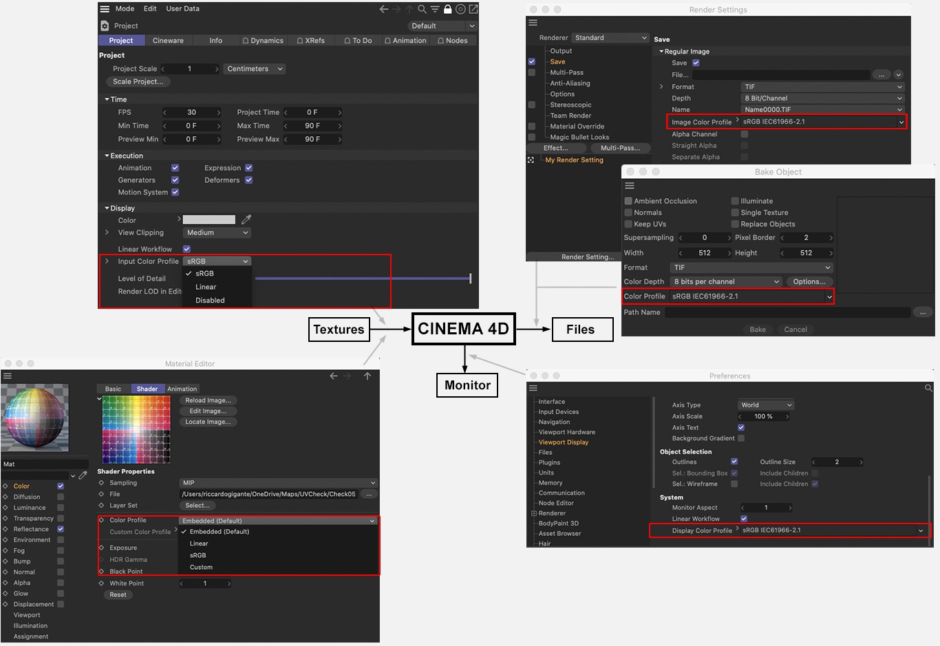 The most important color profile settings in Cinema 4D.
As you can see here, there are virtually 3 "interfaces" to/from Cinema 4D, where color profiles (or device profiles) are evaluated:
- Textures: You can load bitmaps in various material channels or image nodes. The project preferences are used to set whether and how the color profiles of loaded textures are handled. You also define here which color space is to be used if bitmaps do not have an integrated color profile. For individual channels (per bitmap shader) or image nodes, it is also possible to individually define how the bitmap is to be handled.
Furthermore, there are some commands and locations within the BodyPaint 3D layouts where color profiles can be changed (e.g., Bitmap Layer or Change Profile...). - Monitor: set your individual (preferably calibrated) monitor device profile here. This is responsible for the color display of Cinema 4D on your monitor, i.e. what you see in color selection fields, in the Editor Viewport, Picture Viewer, etc. Also not unimportant when you consider how often you select colors within Cinema 4D
- Files: i.e. rendered bitmaps (videos rendered from Cinema 4D cannot be provided with color profiles); here you can define the output color profile that is stored in the file and is taken into account, for example, when opening in Adobe Photoshop.
A list of all image formats that can handle color profiles can be found in the appendix.
Details can be found under Color management (sRGB is correct in most cases).
Here you define 3 things:
- Should the embedded color profile of textures be used or not.
- Which color profile should be used for textures WITHOUT an embedded color profile?
- Which color profile should program color selection fields, color gradients, etc. have?
The text field below shows exactly what the selected option does.
As long as textures have embedded color profiles, these options define how the color selection fields, color gradients, etc. are displayed in Cinema 4D. sRGB is the usual display mode (so always use this when in doubt). Linear is the unusual option that is more difficult to operate.
In this mode, embedded color profiles of textures are NOT taken into account, but an sRGB color space is always assumed. If the Linear workflow option is deactivated at the same time, this corresponds to the mode known from earlier Cinema 4D versions (< R 12).