Reflectance
General
The Reflectance channel is an enhanced version of the previous Reflection channel. The following modifications were made for R16:
- Due to their similarity, the Reflection and Specular channels were merged.
- Reflections/specular highlights can be organized in stacked layers.
- Numerous properties can now be defined per Reflectance layer. Many of these properties were available as separate material channels (Bump, Normals, etc.) or shaders (Fresnel reflections) prior to R16.
- Very many properties can now be controlled per texture.
- New functions such as various reflectance models, anisotropic, textiles, color bleeds at the edge of a reflection, etc.
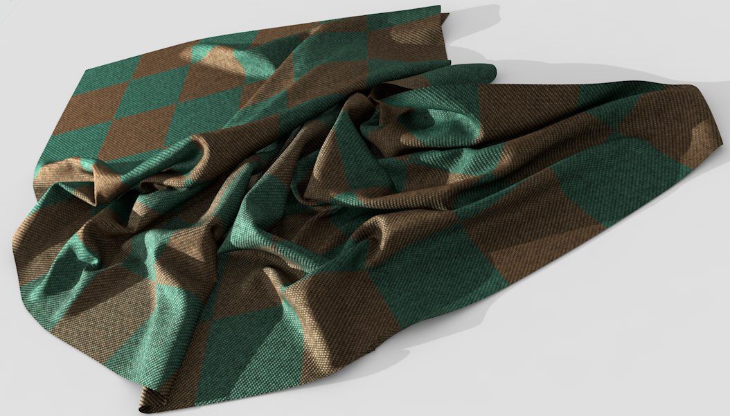
 Great-looking stacked, reflective and even scratched lacquered surfaces or cloth can be created using the Reflectance channel.
The Reflectance channel leaves almost nothing to be desired with regard to reflections. Materials such as car or metallic lacquer that are made up of several layers, each of which reflect light differently, are easy to create. Simply stack the respective Reflectance layers.
It is possible to define a material only using the Reflectance channel (see also PBR Approach or Where are the color, bump and specular textures added?), which means that the Color channel can be ignored in some cases. However, this should not be done across the board.
On the one hand, special effects that were previously difficult to create - such as car lacquer, stacked specular highlights, etc. - can be created using the Reflectance channel. On the other hand, Global Illumination (for the Standard and Physcial Renderers) bases its function on the Color channel's settings (and not on reflections) and cannot do without the Color channel. Furthermore, real diffuse reflections are much more complex to render than are those generated using the Color channel.
How can a metallic look be created?
We'll use an example with 2 layers: a metallic, sparkling effect with a clear coat layer on top.
-
Create a new material, switch to the Color channel and define a color, e.g., dark red.
-
Switch to the Reflectance channel's Layer tab and double-click on Default Specular and rename it ,Metallic’. Set this layer's Type to Beckmann.
-
We will add tiny metallic flakes to this layer. To do so, open the Bump Strength setting's menu (small black triangle) and set Mode to Custom Bump Map. Load a Noise shader into the Custom Texture field. Do not load a texture!
-
Very small Global Scale values in combination with the Mod Noise type work best in the Noise shader. The metallic effect can be enhanced by moderately increasing the Low Clip value.
-
Switch back to the Reflectance channel's Layer tab and set the Reflection Strength slider to a value of 100%.
-
In the Layer Color menu, define a color similar to that of the Color channel but slightly brighter. This completes the first layer.
-
Click on the Layer tab and Add … a new Beckmann layer. Double-click on this layer's name and rename it ,Clearcoat’.
-
Switch to the Layer Fresnel menu and set Fresnel to Dielectric. Set Preset to Glass. That's it. If you now render your object (including an HDR image placed on a Sky object), you will get the following result:
 A metallic car lacquer that reflects its environment.
PBR Approach or Where are the color, bump and specular textures added?
PBR General
PBR (Physically Based Lighting) is an approach for rendering as realistically as possible. PBR is not a fixed, unshakeable rule but an approach that is made up of a series of measures designed to achieve this, if possible.
Note the following for Cinema 4D:
- Use a PBR material (see New PBR Material or a node-based material) that takes into consideration slight reflections of diffuse reflection elements (in reality, even objects that don't have reflective properties can reflect to a certain degree).
- Use PBR lights (see PBR Light). These are area lights with area shadows and inverse square falloff.
- Use the camera's PBR settings (located primarily in the Physical tab) with the Physical Renderer.
- Set your scene to a realistic scale. If an object is 5m long in reality it should also be so in Cinema 4D.
- Consider using Tone Mapping to affect the allocation of light in the image instead of defining unrealistic values to lights.
Textures
Textures often have separate color, bump and specular maps. You have to differentiate between:
- the physically correct PBR approach (slower in conjunction with the Standard or Physical Renderers)
- the older Color channel workflow, which works with GI (e.g., in conjunction with the Stanard or Physical Renderers)
The following applies to the PBR approach (in conjunction with PBR Material):
- The color texture belongs in the Layer Color sub-menu of the Reflectance channel's Default Diffuse menu.
- The bump texture belongs in the Bump material channel.
- The specular texture belongs to the Reflectance channel's Default Reflection menu (in certain cases the specular texture might have to be inverted).
The following applies to the Color channel workflow:
- The color texture belongs in the Color channel (Texture).
- The bump texture belongs in the Bump material channel.
- Specular textures belong in the Texture field in the Reflectance channel's Layer Color menu.
The Reflectance channel as GI Substitute for the Physical Renderer
 No GI was used here. Nevertheless, the reflected light dispersion and caustics rendered correctly.
As described above, the Reflectance channel does not work in conjunction with normal GI methods (see Global Illumination). However, if materials are only used together with the Reflectance channel (this only applies if the legacy Type settings are NOT used), this can serve as a GI substitute. You should also only use objects with luminous materials for lighting - this does not include an HDRI sky.
If other objects’ Reflectance channels reflect these luminous objects in part in a diffuse manner (the Render Settings’ Refraction Strength more-or-less defines the GI sample depth) then you in principle have a type of global illumination. The quality or noise can be adjusted using the matte reflection's settings (e.g., Blurriness Subdivision (Max) for the Physical Renderer).
Render times are comparatively long when using this method. Light-based effects (e.g., Subsurface Scattering), of course, cannot be implemented so easily.
Layer Arrangement
You need this setting in conjunction with the Take function (see the Take Manager). It can be overridden via right-click, which lets you change the layer arrangement for new Takes.
Layers tab
This is where the reflective layers are listed for the currently selected Reflectance material. Each layer can be given a unique name, re-arranged within the hierarchy (simultaneously pressing Cmd/Ctrl will duplicate the layer) or have its effect combined with another layer using one of the two available mix modes.
Up to 16 layers can be created. When a new material is created, the Default Specular layer will be created by default, which corresponds to the pre-R16 Specular channel (a reflective layer can be added by clicking on the Add... button and selecting one of the 5 available types).
If the material channel's Transparency channel is enabled, the *Transparency* layer will be displayed in the Reflectance channel's Layer tab (for inner total reflexions, this layer controls the reflection settings for total reflexion).
How many layers are needed? As many as in the real world. For example, if you have an object with a metallic lacquer and a clear coat. This material will need an anisotropic reflective layer that represents the metal surface as well as a slightly reflective layer for the clearcoat. These will be stacked as they would be in reality - from bottom to top:
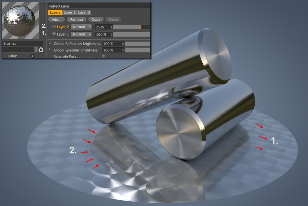 The 1st layer represents the brushed metal and the 2nd layer is the clearcoat.
Add
Click on this button to add a new layer. A selection menu will appear from which you can select the desired Types. If you do not want to create anisotropic effects or weaved textiles, the Beckmann option should be selected. Please refer to the aforementioned link for details.
Remove
Click on this button to remove the currently selected layer from the list.
Copy/Paste
Use these buttons to copy and paste layers to the very top (also into a different material), including all of their settings.
Right-clicking on a layer will open a context menu from which the following commands can be selected:
Duplicate
Duplicates the selected layer and places it at the top of the list.
Click on the eye icon at the left of a given layer to turn it on or off. The layer's name can be changed by double-clicking on it.
The selection menu at the right of the layer's name lets you select between two modes:
- Normal: Select this mode for all reflective layers. The slider at the right can be used to adjust the layer's opacity. A value of 100% will cover the underlying layer(s) completely. Exception: activated masks or Fresnels can let the underlying layer(s) show through.
- Add: Select this mode for layers that are solely specular (multiple specular highlights can be stacked additively). The slider at the right can be used to adjust the layer's opacity.
Global Reflection Brightness[0..1000%]
Compared to the layer's own Reflection Strength setting with which the reflection strength is defined per layer, the Global Reflection Brightness setting regulates the strength of the overall reflection. For example, if you create a complex combination of reflections, each with its own reflective strength and the overall reflection is too intense when rendered, this slider can be used to tone the reflection down without having to adjust individual reflection settings.
Global Specular Brightness[0..1000%]
Just as the Global Reflection Brightness setting can be used to adjust or fine-tune a material's overall reflection, the Global Specular Brightness setting can be used to do the same for the specular brightness.
This option is useful in combination with Multi-passes (see here). Enable this option if you want to output specific materials in separate passes.
Linear Color Space Fix
First off: This option is only visible after a Project is loaded that was created using the Cinema 4D R16 release version. The option will then be disabled. The reason for this is that, due to a bug in the aforementioned version, textures in the Reflectance channel were not evaluated correctly (sRGB instead of linear). This is done automatically in the new version. This option ensures that old Project files render identically to the new files (the option is then disabled).
The remaining tabs
Preview
 Available preview types, which can be selected in the Type menu.
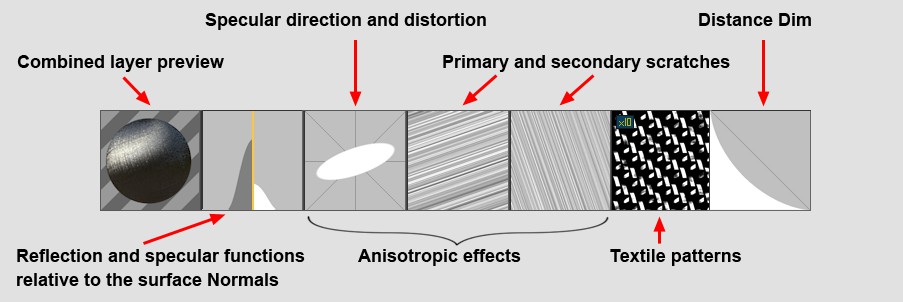
The preview shows the effect of the defined settings on the currently selected layer. From left to right:
- Layer preview: displays the combined effect of a layer's settings
- Falloff function the reflection and specular strength relative to the surface Normals (0°-90° to camera's angle of view)
- Shows the anisotropic specular highlight distortion and direction. This and the next two previews will only be displayed if Type is set to Anisotropic and Primary + Secondary Scratches.
- Primary Scratches
- Secondary Scratches
- The defined cloth pattern with Type set to Irawan (Woven Cloth)
- Reflection falloff if Distance Dim is enabled
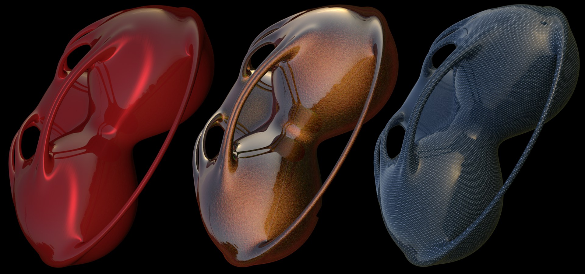
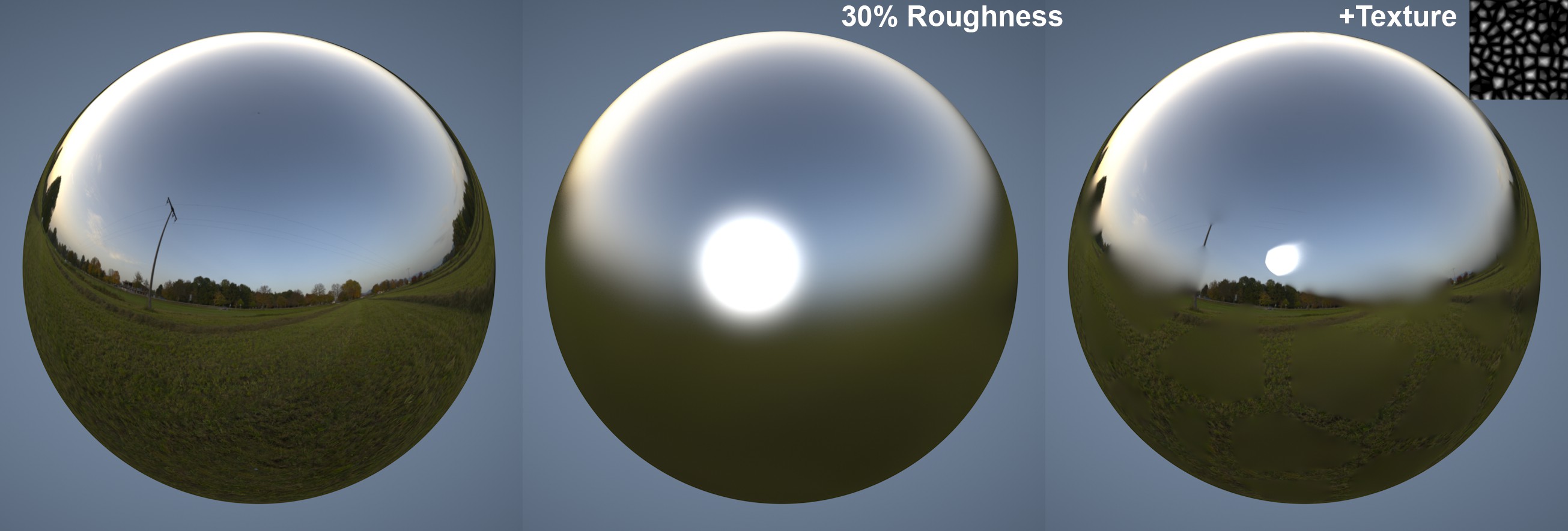
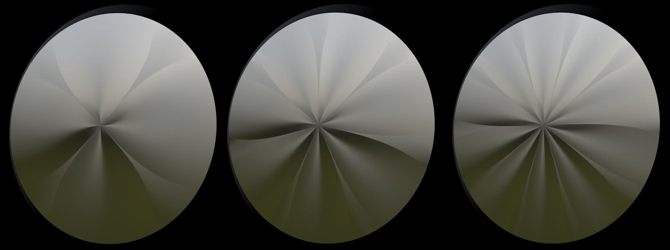
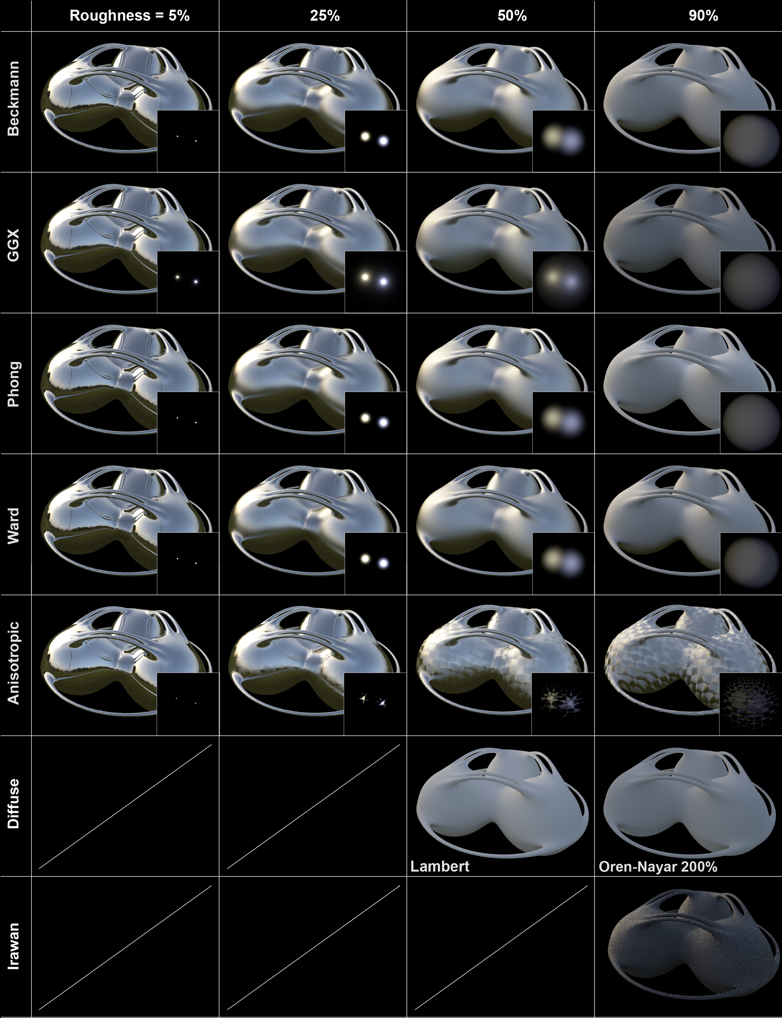 The various Type settings with different Roughness values. The large, reflective object reflects a HDRI sky, the depictions inset each show the specular highlights from two light sources. Both the diffuse and the Irawan options produce a result very different from the rest because they do not allow Roughness to be defined separately (exception: Oren-Nayer).
The illumination examples displayed here show how light is dispersed relative to the angle of incidence and the angle of reflection (in principle, an empirical approach to ascertainable BRDF functions).
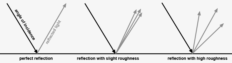 These modifiable types apply only to matte reflections.
Dispersion of light is a product of matte reflections. These types have no effect on surfaces with perfect reflections (Roughness set to 0%).
The subject of the following text will not be the theory behind each type because this would require going into far too much mathematical detail. We'll keep the explanation brief:
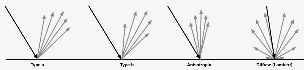
- Beckmann, GGX, Phong, Ward: These types are functions that only differ in the manner with which they uniformly weaken reflections from the ideal reflection angle (= angle of incidence). This can occur slower/faster or stronger/weaker. Basically only variations of Type a and b shown above. If you take a look at the different depictions you will see that the differences are only very slight.
Beckmann is a physically correct and fast type and should therefore be the preferred method for normal use. GGX produces the greatest dispersion and works best for simulating metal surfaces (see top depiction, 2nd row, 2nd column): a bright specular highlight with diminishing brightness. Ward is best suited for soft surfaces such as rubber or skin.
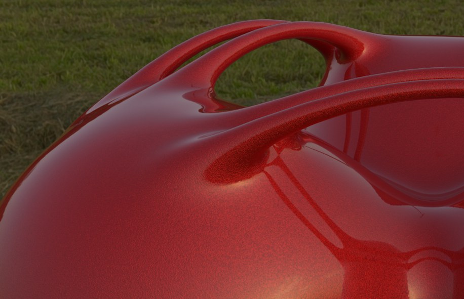
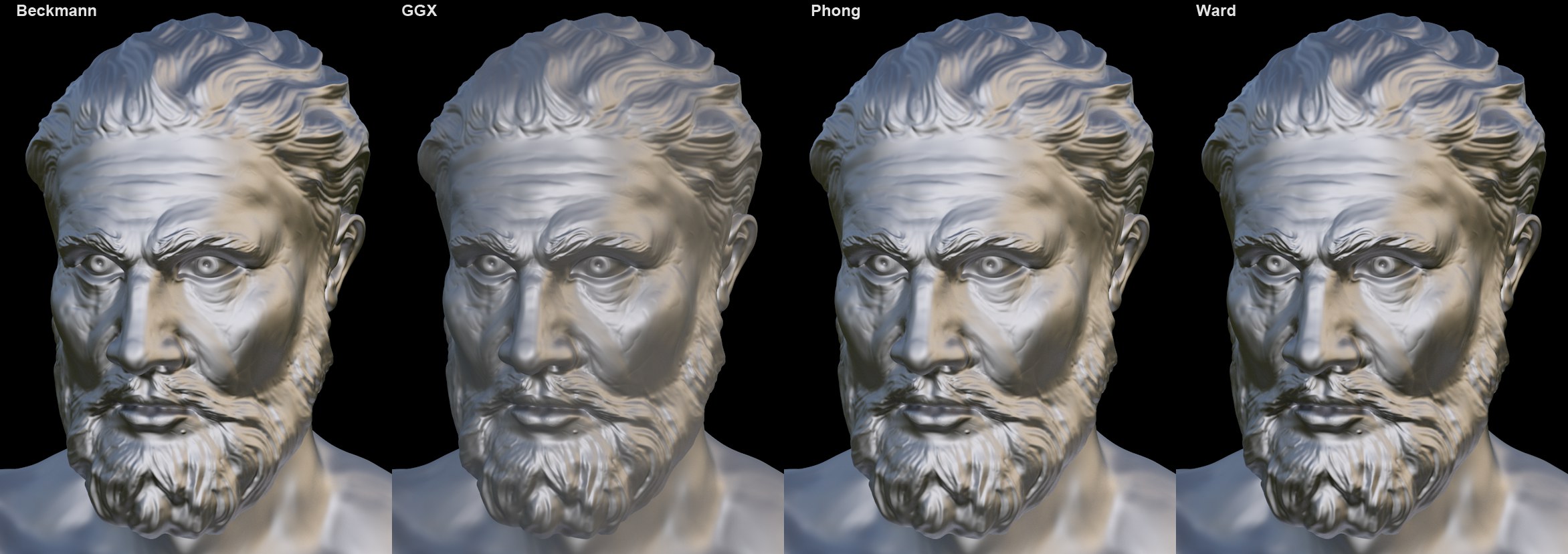 The four most important types shown on a real-world reflective model (© Eric Smit) with 60% Roughness.
- Anisotropic bends the reflected bundle of rays in certain directions, which produces a distortion of the reflection, as with brushed or scratched metal, for example.
- Reflection (Legacy), Specular Blinn/Phong (Legacy): These three are only available for reasons of compatibility if an older Project file is loaded. It is recommended that a different mode be used that works physically correct. Specular highlights can be adjusted freely (without having to take roughness into consideration) if Specular Blinn/Phong (Legacy) is selected.
- Lambertian (Diffuse), Oren-Nayer (Diffuse): These modes are somewhat different in that they are diffuse models (i.e., ,perfect’ matte reflections). They produce a result similar to the material channel Color (which doesn't reflect). These channels should be used with caution (they can't be cached by GI's Irradiance Cache). Normally, the Color channel should be used instead, also because it simply renders faster.
- Irwan (Woven Cloth) is a type of special anisotropy that contains several cloth patterns internally that can be used to create realistic-looking cloth surfaces.
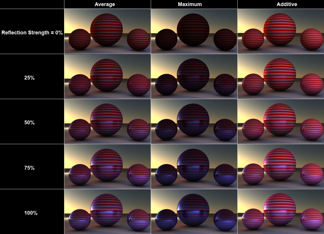 The sphere material has a red-and-white striped Color channel and is and has a Reflectance channel with its Layer Color set to blue.
The options in this menu are designed to be used in conjunction with the material channel Color:
These options define how the Color channel should be mixed with the layer color (sub-menu Layer Color) with various Reflection Strength settings. If the Color channel is disabled, these settings will have no effect! Note also that if an older specular type is selected, which is made available only for reasons of compatibility, only those modes available for older Cinema 4D versions will be made available (Additive and Metal).
In the real world, the Color channel's effect weakens as the surface's reflectivity increases, which is something that the Additive mode ignores completely.
- Average: Both colors will be averaged (reflects the previous Additive option when disabled (pre-R15)). This mode does not differ from the next mode, Maximum, if no color is defined in the Color setting (sub-menu: Layer Color). This mode produces the most realistic-looking results.
- Maximum: This mode is best suited for creating colored reflections: The Color channel's effect will be reduced and the color defined below will dominate.
- Additive: Both colors will be added (not physically correct; the Color channel must be darkened manually).
- Metal: Only available for reasons of compatibility if an older Project is loaded (in older versions of Cinema 4D, this mode could be found in the Specular channel's Mode setting and it used the color defined in the Color channel to color the specular highlight).
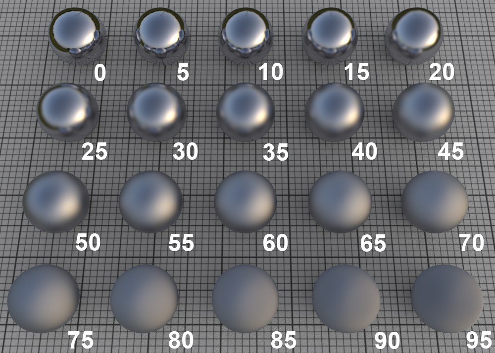 Various Roughness values that increase in steps of 5.
In the real world, surfaces are made up of an innumerable number of microscopic reflective facets, each with a different orientation, which, when viewed from a distance, produce a specular highlight or reflection.
A perfectly polished (reflective) surface is made up of facets with the same orientation. The rougher a surface is, the more random the orientation of these micro facets is, which produces a correspondingly more spread out and duller specular highlight. A roughness of 100% is referred to as a Lambertian material (see depiction above). This type of surface reflects light in a circular dispersion in all directions, which constitutes a perfect diffuse material. This is exactly what is defined in the material channel Color: a diffuse material's color without reflective properties. You can even ignore the Color channel completely and use the layer color to control the diffuse material color (which, however, takes longer to render).
Note that the render time will increase accordingly with increasing roughness because reflections from a correspondingly wider range of reflections must be included.
 Matte reflections can be controlled using textures.
The Texture setting can be used to apply the previously described setting to an entire texture. The grayscale values of the texture loaded here control the setting as follows: white represents the setting’s full value and black = 0. In-between gray values have a corresponding effect.
Anisotropic (see below) can be used to reduce the randomness of the orientation of the micro facets.
Reflection Strength[0..10000%]
This setting defines the strength with which the material should reflect. The Attenuation setting above defines how this setting should work in conjunction with the material channel Color.
Generally speaking, the intensity of the material's color should subside accordingly as the strength of the reflection increases (which occurs for all modes with the exception of Additive). This effect is also known as energy conservation.
If this value is set to 0%, the material will not reflect at all; a value of 100% will produce the maximum amount of reflection. Every material in the real world reflects to some degree, even if it is very minor. Keep this in mind when creating highly realistic textures.
The Texture setting can be used to apply the previously described setting to an entire texture. The grayscale values of the texture loaded here control the setting as follows: white represents the setting’s full value and black = 0. In-between gray values have a corresponding effect.
If this option is enabled, the Color defined in the material channel Color will be used as the reflection color (which is normally defined by the Color setting in the Layers Color sub-menu).
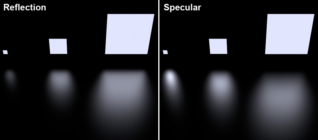
This value defines the strength of the specular highlight. The use of specular highlights is a (simplified and much faster to render) trick to add reflections to materials without noticeably increasing render time. In the real world, specular highlights are nothing more than light sources reflected in objects’ surfaces. If you want to create a photo-realistic scene, set this value to 0 and use the Reflection Strength setting instead.
The size and appearance of specular highlights (with the exception of Type = Specular Blinn/Phong (Legacy)) depends on the Type, Roughness - this must be set to a value greater than 0% for most modes - and in some cases the anisotropic settings. This is different from pre-R16 versions of Cinema 4D, which let you make physically incorrect adjustments to the specular highlight's height and width. This can, however, still be done, if necessary, if Type is set to Specular Blinn/Phong (Legacy).
Each light source in a given Project generates specular highlights. Note that specular highlights are only generated by real Cinema 4D light sources - as well as by Area lights (however, these differ in size and other aspects from real, reflected Area lights):
 3 Area lights are reflected in the floor.
Note how the small Area light is rendered far too large, making it look unrealistic. Note in conjunction with this both light source options Show in Specular and Show in Reflection, which can be defined individually for each light.
See Typ for example images that show the effect of different Type and Roughness settings.
The Texture setting can be used to apply the previously described setting to an entire texture. The grayscale values of the texture loaded here control the setting as follows: white represents the setting’s full value and black = 0. In-between gray values have a corresponding effect.
If this option is enabled, the Color defined in the material channel Color will be used as the specular highlight color (which is normally defined by the Color setting in the Layers Color sub-menu).
Cinema 4D specular highlight settings
The following 3 settings apply only to Specular Blinn/Phong (Legacy):
Use these settings to define width of the specular highlight. Larger widths should be used for matte surfaces (for less specular strength). Polished and shiny surfaces should have very small widths (for greater specular strength).
The Texture setting can be used to apply the previously described setting to an entire texture. The grayscale values of the texture loaded here control the setting as follows: white represents the setting’s full value and black = 0. In-between gray values have a corresponding effect.
The Falloff value defines the curve of the specular highlight - anything from pinpoint to bell-shaped or rectangular shapes can be created.
The Texture setting can be used to apply the previously described setting to an entire texture. The grayscale values of the texture loaded here control the setting as follows: white represents the setting’s full value and black = 0. In-between gray values have a corresponding effect.
This value defines the specular highlight's inner region, which is not affected by abatement of brightness.
The Texture setting can be used to apply the previously described setting to an entire texture. The grayscale values of the texture loaded here control the setting as follows: white represents the setting’s full value and black = 0. In-between gray values have a corresponding effect.
Bump/Normals channels
 The metallic glitter and the scratches were each created using separate Noise shaders in both reflection layers.
Each reflection layer has its own, autonomous Bump and Normal channel (as such, they function exactly like the material channels of the same name).
A very common use for layer-specific Bump channels is for glitter in metallic car lacquer. The reflective particles are simulated using a very small Noise Texture.
Use this slider to adjust the strength of the bump effect. If set to 0%, the effect will be disabled; 100% is the maximum effect. This slider can be used to adjust the Bump effect as well as for Normals.
Each layer channel has its own Strength slider but they work differently (for example, the Bump slider also allows negative values).
The Texture setting can be used to apply the previously described setting to an entire texture. The grayscale values of the texture loaded here control the setting as follows: white represents the setting’s full value and black = 0. In-between gray values have a corresponding effect.
Default
This setting defines the type of Bump or Normal channel that should be used (no specific reflection layer channels).
Custom Bump Map
Select this mode if you want to use a custom bump map. Load it into the Custom Texture field. You can also load a normal map (using the next option; this can also be a bump map in a Normalizer shader) for better results.
Custom Normals Map
Select this mode if you want to use a custom normal map. Load it into the Custom Texture field.
Load your custom bump or normals map into this field.
Use this value to define the strength of the bump/normal mapping. Details can be found under Strength (bump) and Strength (normals).
Enabling this option will reduce the bump mapping the farther away it is from the camera (see also MIP Falloff).
Use this setting to define the coordinate system for the Normals map. Details can be found under Method.
Use these settings to define which axis should have which color. Details can be found under Flip X (Red).
Layer Color
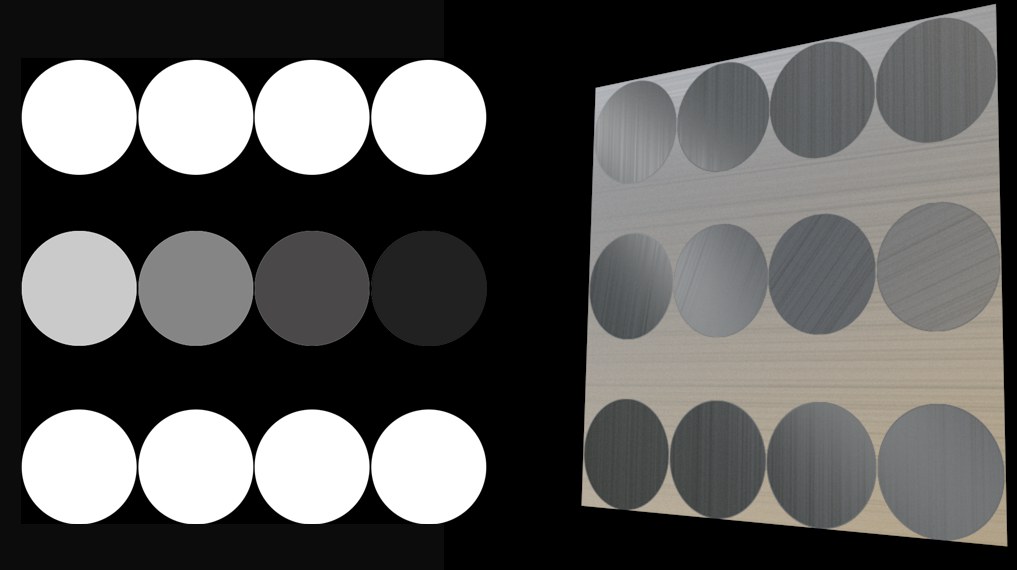
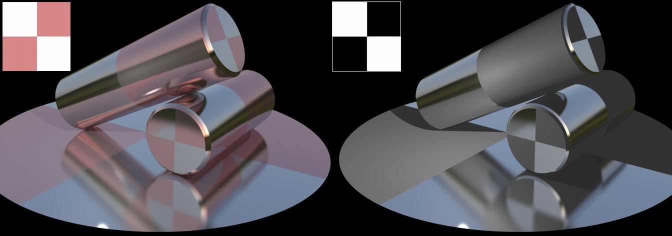 The textures from the Layer Color menu. White produces total reflection, black shows the Color channel's color.
This menu's settings serve as a type of color filter for the reflections. The layer color and the color from the material's Color channel will be added. This method lets you use a black-and-white texture to define where reflections should take place (white=yes; black=no).
This is also the color you should use if you want to create colored metal surfaces.
This defines the layer filter color. The default color is white, which allow reflections without having to modify the color.
Use this setting to adjust the brightness of a channel’s color. The Brightness setting functions somewhat like a multiplier and can be set to greater than 100%.
Here an image texture or a 2D shader can be defined. Refer to the Textures chapter for details.
Use these parameters to mix the color and texture panes using one of four modes. The default mode for all channels is Normal, except for the Environment page, which uses Multiply as the default mode. Not all channels have Mix settings. If you load a texture or a 2D shader, it is placed on a layer above the color (i.e. the texture is placed on top of the color).
Mix Strength defines the mixing proportion between the texture and color panes or between the brightness and transparency (depending on which mode is selected) of the texture to be mixed.
Layer Mask
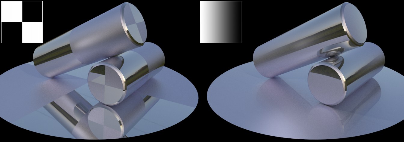 The textures from the Layer Mask menu with 2 different reflection layers. White allows the entire layer to be shown, black masks it.
This menu's settings can be used to create an alpha channel for a layer that defines the visibility of the layer beneath it. White will not hide anything, black hides all, grayscale values hide accordingly.
Use this setting to adjust the brightness of a channel’s color. The Brightness setting functions somewhat like a multiplier and can be set to greater than 100%.
This setting is used to define the color of the alpha. The default color is white, which allow reflections without having to modify the color.
Here an image texture or a 2D shader can be defined. Refer to the Textures chapter for details.
Use these parameters to mix the color and texture panes using one of four modes. The default mode for all channels is Normal, except for the Environment page, which uses Multiply as the default mode. Not all channels have Mix settings. If you load a texture or a 2D shader, it is placed on a layer above the color (i.e. the texture is placed on top of the color).
Mix Strength defines the mixing proportion between the texture and color panes or between the brightness and transparency (depending on which mode is selected) of the texture to be mixed.
Layer Anisotropy
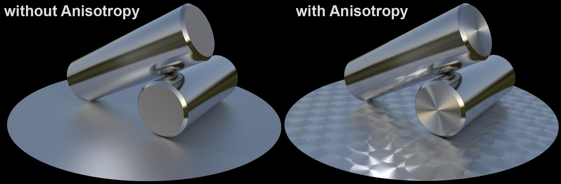 Left: no anisotropy; right; anisotropy with various Roughness settings. A HDR image placed on a Sky object is used to create the reflections.
Anisotropic effects are produced when many fine microscopic scratches are oriented in a specific direction on an object's surface (as is the case with brushed metal, for example). Specular highlights and reflections will then be "dragged” in the direction of these scratches. In addition to microscopic scratches, larger ridges can also be created in the direction of the scratches.
To create an anisotropic effect, set Type to Anisotropic, Roughness and Anisotropy to a value greater than 0%. Also make sure that there is enough present in the environment to reflect. HDRI textures on a Sky object are well-suited for this. In case you're wondering how the Anisotropic pattern is projected onto an object: this process follows the normal rules of projection. As a test, set Scratches to Primary - a corresponding preview will be displayed at the top of the Material Editor. Imagine this preview being projected as a texture.
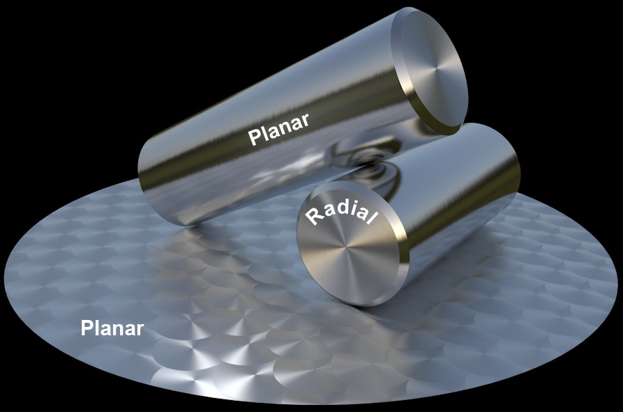 Radial only for the disc. Different materials for the cylinder heads and sides (Planar and Radial).
The scratches’ vector tangents, that define the scratch direction internally, can be projected onto an object in one of two ways:
- None: Vectors will be projected onto the object without modification
- Planar: Vectors will be scaled, rotated and moved
- Radial: Vectors will be curved circularly, e.g., to simulate the look of the disc in the image above. An image can be loaded into the Pattern field, Offset values can be increased and Count can be varied to create all kinds of interesting spiral/symmetrical effects but the effect in the example above can only be created without using the Pattern setting.
This value defines the size of the Pattern or Scratches selected.
This setting is used to rotate the anisotropic microscopic scratches (and, if defined, the parallel ridges). The rotational axis is defined by the Offset U/V values.
These settings are used to move the Pattern/Scratches in the U and V directions, respectively. For the effect on the disc in the image above, both values were set to 50%, which means that the rotational axis lies at the center of the circular scratches.
Count
 Increasing Count values from left to right.
When applying this setting, a Pattern should be selected first. The Count value then defines the number of ‘threads’ that converge at the center defined by the Offset U/V settings.
This setting can be used to create common anisotropic materials such as carbon, brushed metal, etc. In addition, textures can be used to create numerous other patterns.
None
Linear scratches whose orientation will remain constant will be created.
Circular
Box
Diagonal
Lattice
Custom
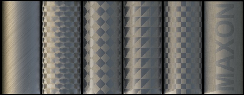 From left to right: None, Circular, Box, Diagonal, Lattice, Custom.
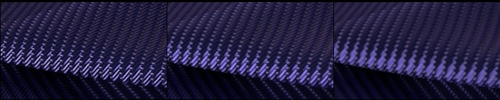
Lattice and Box are well-suited for creating carbon fiber surfaces:
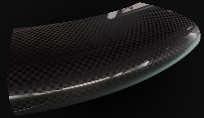 The fitting pattern can be used to create a carbon fiber material. Here, an additional reflective layer was added to the anisotropy layer.
 The texture on the left produces the scratch pattern on the right (Max Angle set to 90°).
Instead of using a default pattern, you can also use a custom pattern. To do so, create a black texture with a white pattern on it.
Grayscale values will also be evaluated, whereby Max Angle will represent the scratches’ angle at white regions. Note that you will not see the difference if a scratch is rotated 180°.
This setting offers options that let you mirror the Pattern in the U and or V directions (with the exception of Custom patterns).
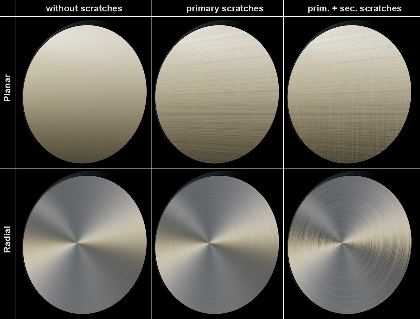 Primary and secondary scratches in Planar and Radial modes.
Besides anisotropic microscopic scratches that can uniformly deform specular highlights/reflections, additional, even larger ridges can also be defined. There are primary ridges that run parallel to the microscopic scratches and secondary ridges (these make less sense in conjunction with Re-projection Radial) that run in a perpendicular direction. Both ridge types can be applied simultaneously, as shown at the top right of the image above.
Use this value to define the over strength of the anisotropy effect. A value of 0% will disable the effect.
The Texture setting can be used to apply the previously described setting to an entire texture. The grayscale values of the texture loaded here control the setting as follows: white represents the setting’s full value and black = 0. In-between gray values have a corresponding effect.
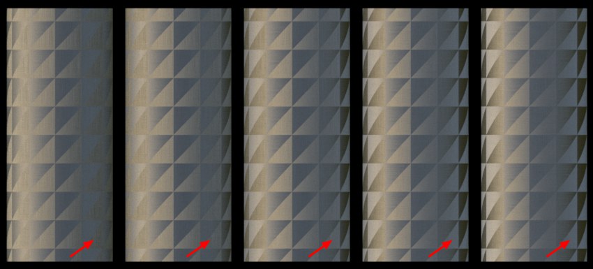 Various Orientation values. Note the changes at the marked locations.
This setting is a little more difficult to comprehend than the others. It regulates a property that does not actually exist in the real world: it rotates the vector tangent scratches mentioned above. What effect does this have? It changes the reflective behavior. This makes it possible to fine-tune the anisotropy effect without having to change the position of the light source.
The Texture setting can be used to apply the previously described setting to an entire texture. The grayscale values of the texture loaded here control the setting as follows: white represents the setting’s full value and black = 0. In-between gray values have a corresponding effect.
Secondary Amplitude[0..10000%]
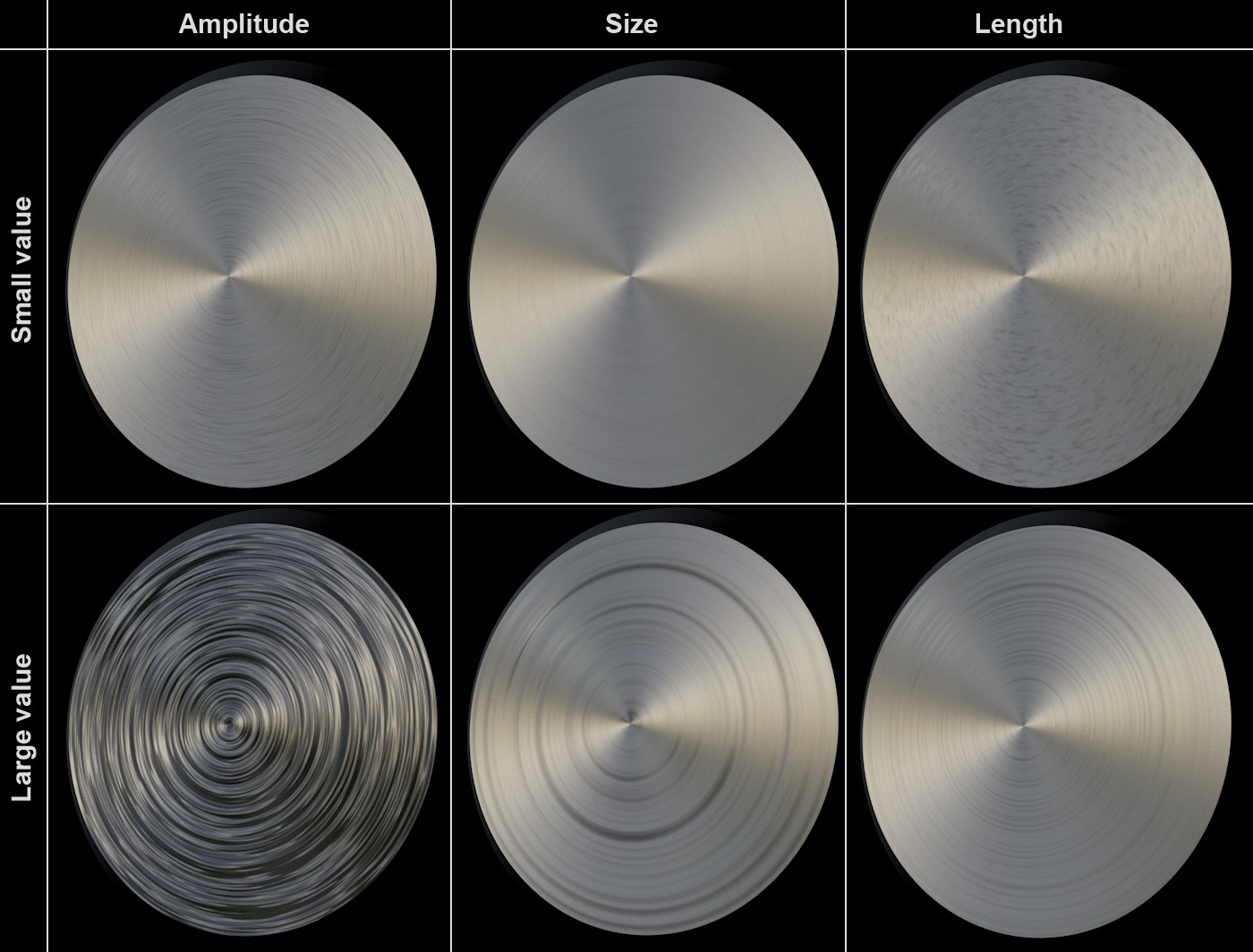 Small and large values for amplitude, scale and length.
These values are used to define the ridge depth. Note that you can also enter values in excess of 100% to create very deep ridges.
The Texture setting can be used to apply the previously described setting to an entire texture. The grayscale values of the texture loaded here control the setting as follows: white represents the setting’s full value and black = 0. In-between gray values have a corresponding effect.
These settings are used to define the ridge width.
The Texture setting can be used to apply the previously described setting to an entire texture. The grayscale values of the texture loaded here control the setting as follows: white represents the setting’s full value and black = 0. In-between gray values have a corresponding effect.
These values are used to define the ridge length. Very high values lead to concentric (radial) or long ridges with a uniform depth (Planar), very small values lead to very short ridges.
The Texture setting can be used to apply the previously described setting to an entire texture. The grayscale values of the texture loaded here control the setting as follows: white represents the setting’s full value and black = 0. In-between gray values have a corresponding effect.
Primary Attenuation[0..10000%]
Secondary Attenuation[0..10000%]
These settings are similar to MIP Mapping for calculating ridge patterns based on their distance from the UV dimensions. In essence, they control the smoothing of the ridges. Small values produce more grainy but faster results and larger value produce correspondingly more blurred and slower results. Note that very large values can be entered here.
The Texture setting can be used to apply the previously described setting to an entire texture. The grayscale values of the texture loaded here control the setting as follows: white represents the setting’s full value and black = 0. In-between gray values have a corresponding effect.
Layer Cloth
Cloth is most often made of yarn (and this in turn from fibers) that are woven to create a certain pattern. They are made up of structured surfaces that produce characteristic anisotropic specular highlights/reflections. This is why Cinema 4D has its own cloth mode - Irawan (Woven Cloth) - which can be selected in the Type menu.
The material channel Color can be disabled in conjunction with this mode.
Here you will find a selection of presets with predefined values for each respective weave pattern.
The following presets are available:
If a preset's settings are changed, it will automatically switch to Custom mode.
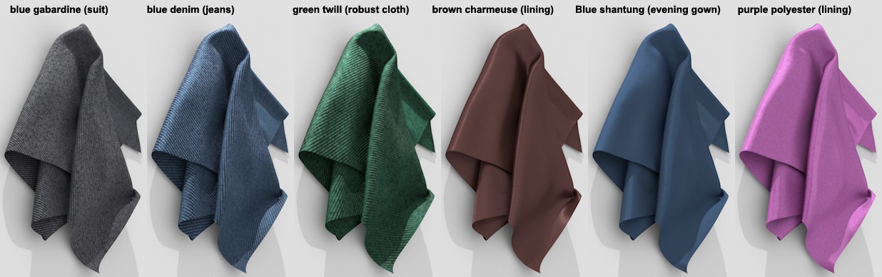
Woven cloth is made up of various warp and weft threads that are woven perpendicular to each other. When viewed close up, the Cinema 4D weave patterns look like this:
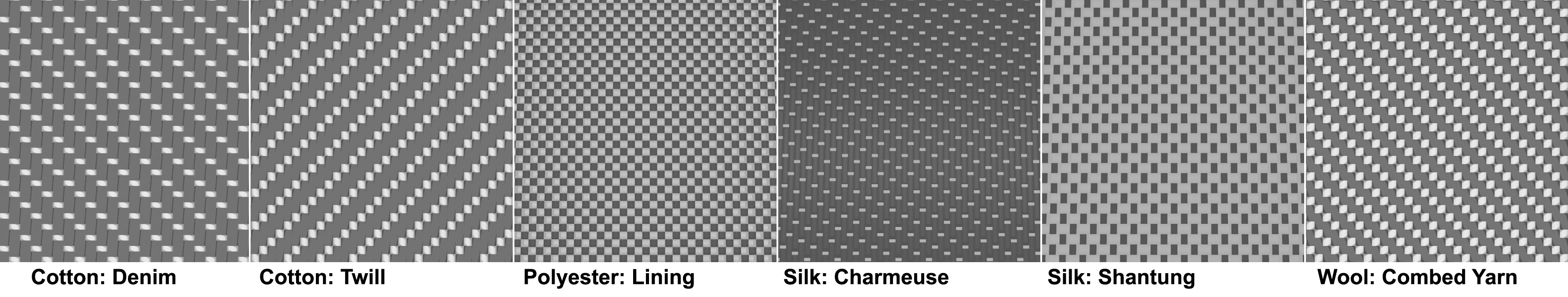 Various weave patterns. Warp and weft patterns in dark and light gray.
When viewed from a distance, these structures blend to form a characteristic cloth, which looks slightly differently, depending on the angle from which it is viewed. This isn't surprising considering the fact that, in reality, warp and weft threads are made up of different yarn with different reflective properties. Polyester: for example, lining is made of very shiny elements that lie perpendicular to each other and have strong reflective properties (as can be seen at the far right of the image above).
Internally, the reflective behavior of the weave pattern is treated like a procedural texture with a strong noise property (analog to the Noise shader, this would reflect a small scale value). When rendered, this texture will be evaluated using various small samples. The three quality levels available here are used to adjust the sample count. The effect this has on render quality is minor (although it has a huge effect on render time) if you do not use the Low option, which is designed for creating test renderings.
The better the antialiasing settings, the less the Quality setting will affect render quality.
The higher the quality, the sharper the cloth structure will be the more the Moiré pattern is reduced.
This setting can be used to rotate the cloth structure (rotational axis U/V=0/0). For example, if a pant leg's pattern lies perpendicular to the leg, this setting can be used to correct this state. Depending on the weave pattern, even small modifications (e.g., 10°) can have a major effect on the rendered result. It's a good idea to experiment with this setting a little.
The Texture setting can be used to apply the previously described setting to an entire texture. The grayscale values of the texture loaded here control the setting as follows: white represents the setting’s full value and black = 0. In-between gray values have a corresponding effect.
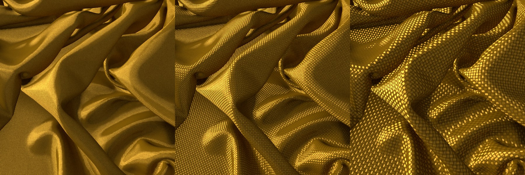 Increasing Scale values from left to right (polyester lining).
These settings can be used to vary the cloth structure in U and V directions. Normally, the scale values should be the same in both directions to correctly reproduce the cloth's structure. However, these values can also be made to differ in order to achieve a special look.
Note that very large values will produce correspondingly unrealistic-looking results.
The Texture setting can be used to apply the previously described setting to an entire texture. The grayscale values of the texture loaded here control the setting as follows: white represents the setting’s full value and black = 0. In-between gray values have a corresponding effect.
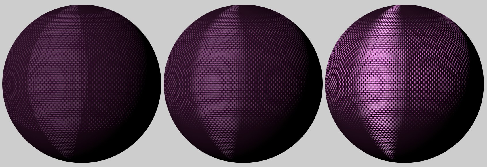
 Increasing Highlights values from left to right.
The Highlightt Width setting defines the ‘width’ of the specular highlight/reflection. Smaller values produce sharp, bright highlights on individual threads; larger values will soften the highlights accordingly (they will become correspondingly darker and more expansive).
The Texture setting can be used to apply the previously described setting to an entire texture. The grayscale values of the texture loaded here control the setting as follows: white represents the setting’s full value and black = 0. In-between gray values have a corresponding effect.
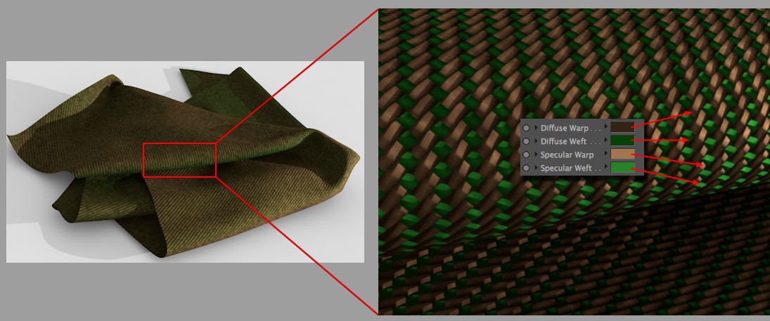
These color settings can be used to define separate diffuse and specular colors for the warp and weft threads (see Cloth Pattern).
Make sure that the specular color is always brighter than the diffuse color and that they have a similar tone. A shader or bitmap can be loaded into the Texture field to define the color. Note that the texture will be multiplied with the respective color. If you only want to use the texture to define the color, then set the color for that setting to white.
 Increasing Smoothing value from left to right.
This setting is for use with the Polyester and Silk Pattern options only. Generally speaking, the anisotropic specular highlight becomes more blurred - but brighter - with increasing values.
Scattering - Uniform[0.00..0.10]
This setting defines the overall specular/reflection strength. The larger the value, the brighter/more reflective the cloth will be.
Scattering - Forward[0.00..10.00]
This setting can also be used to adjust specular/highlight strength - but larger values will produce correspondingly smaller effects. More importantly, this setting primarily affects the bright regions of the yarn's specular highlight and the darker regions will hardly be affected.
Noises
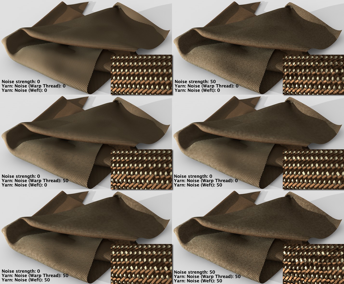 Various Noise effects (insert: greatly enlarged view).
Since just about every cloth has irregularities in its threads and its weave, Cinema 4D offers 3 Noise methods that can be used to simulate such irregularities in cloth:
- Yarn color using Noise Strength
- Shape/orientation of the warp thread's specular highlight using Yarn Noise (Warp)
- Shape/orientation of the weft thread's specular highlight using Yarn Noise (Weft)
This setting is used to define the strength of the noise applied to the yarn's color (the thread color will be brightened and darkened in other regions).
This setting is used to define the scale of the noise applied to the yarn's color. Note that very large values can be used, which will produce a correspondingly spotty cloth.
These settings are used to define the strength with which the internal noise affects the shape and size of the specular highlight (see also image above). The larger the value, the greater the deviation from the parallel thread position and the more the look of the cloth will change - e.g., from a silky surface to a rough canvas-type surface.
This setting is used to define the scale of the noise effect. The smaller the value, the faster the deviation from the optimal shape will be. Larger values will slow deviation correspondingly, exactly like scaling a Noise shader.
Layer Fresnel
These setting are used to define the degree to which the reflection will increase as the surface normals increase their angle to the surface, which is referred to as Fresnel reflection, which should already be familiar to you from the Fresnel-Shader section, which principally works the same.
Make sure that the reflectance strength is greater than 0. Otherwise no Fresnel effect will appear.
You can select from:
- Dielectric for transparent materials such as glass, water, clear coat lacquer, etc.
- Conductor for opaque, reflective materials such as metal, minerals, etc.
Make sure that the material channel Color is disabled for more realistic-looking results. Metal surfaces use reflections almost exclusively.
A series of presets (primarily for metals) is integrated that are based on real-world values. These cannot be modified individually using the Fresnel settings described below.
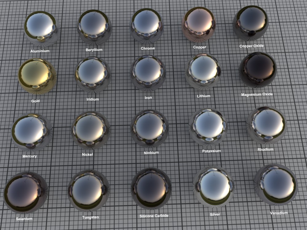 Example: a selection of Conductor presets.
Different materials will be made available for selection depending on the Fresnel mode selected. Select Custom if you want to modify the settings yourself.
Note that the Conductor presets will affect the internal color system (the layer color (Layer Color) should be 100% white!).
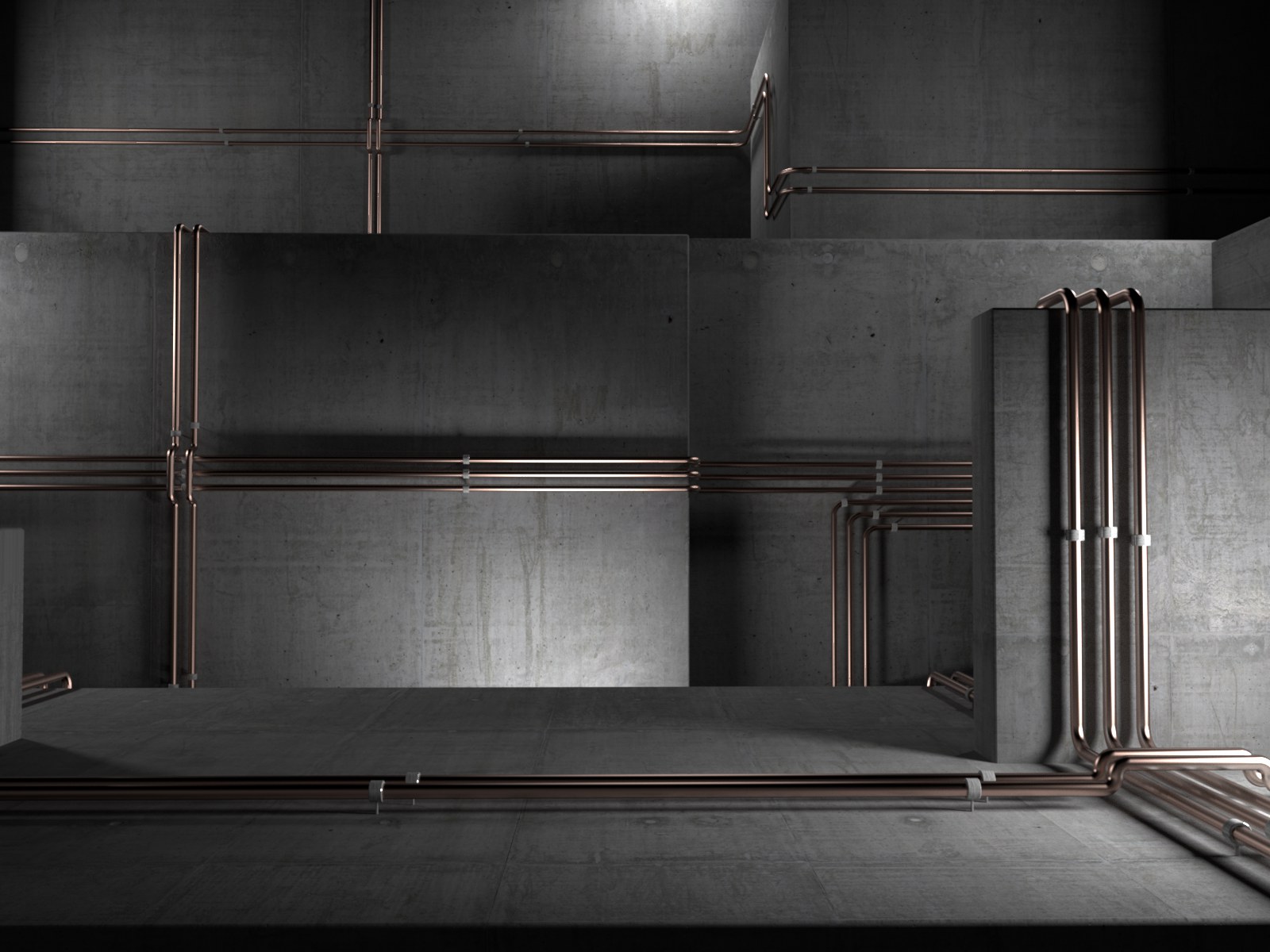
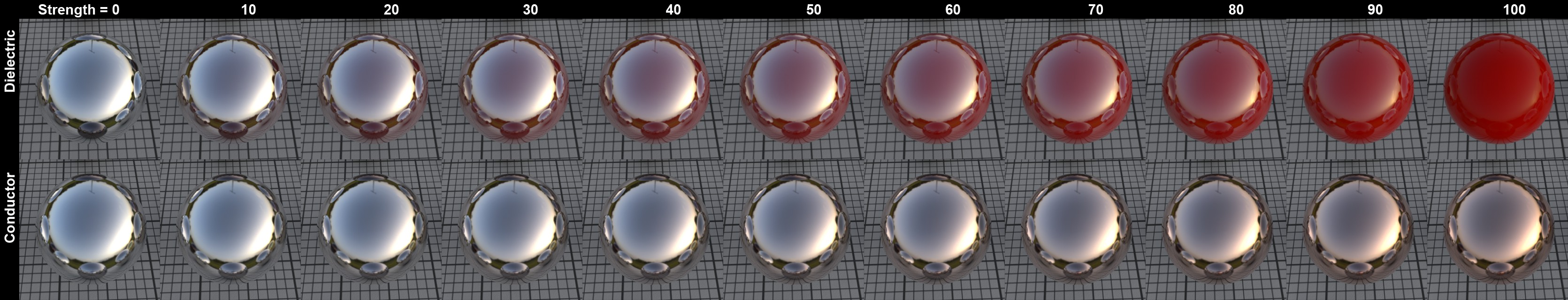 Increasing Strength values for Dielectric and Conductor (copper).
The Strength setting is used to define the reflections strength between 0% and 100%.
The Texture setting can be used to apply the previously described setting to an entire texture. The grayscale values of the texture loaded here control the setting as follows: white represents the setting’s full value and black = 0. In-between gray values have a corresponding effect.
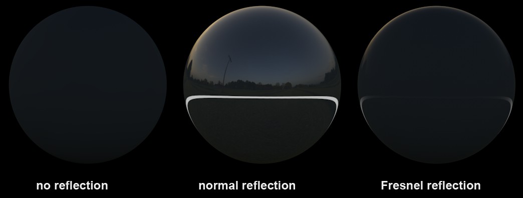
 Increasing IOR values (dielectric material) from left to right.
The IOR is mentioned mainly in conjunction with refractive light effects but it is also a measure for the angle of incidence for a material's light reflections (regardless if it's transparent or opaque). As you can see in the image above, low values cause the material to reflect almost exclusively in regions at which the camera's angle of view is extremely low. Larger values cause the reflection to move correspondingly more to the frontal regions.
The Conductor mode behaves similarly (however, the increase in reflection that corresponds to the increased IOR is not linear because it is also affected by the Absorption value; it is recommended that you use the preset values to achieve a higher degree of realism) but the reflections are generally much more pronounced.
The Strength slider can be used to seamlessly move from reflection (0%) to full Fresnel reflection (100%).
The Texture setting can be used to apply the previously described setting to an entire texture. The grayscale values of the texture loaded here control the setting as follows: white represents the setting’s full value and black = 0. In-between gray values have a corresponding effect.
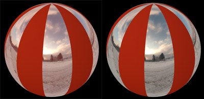
Enable this option to invert the Fresnel reflection. Example (on a sphere): the maximum reflection that is normally at the sphere's center will be switched to its edges.
In some cases you might want to prevent the Fresnel effect from neighboring surfaces from affecting a given object. In the image above, a reflective surface with an alpha map lies on top of a red, diffuse layer. The Opaque option is disabled at the left: note how the red color from the underlying layer shines through while it is blocked on the right side of the image where the Opaque option is enabled.
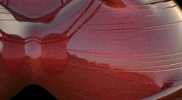
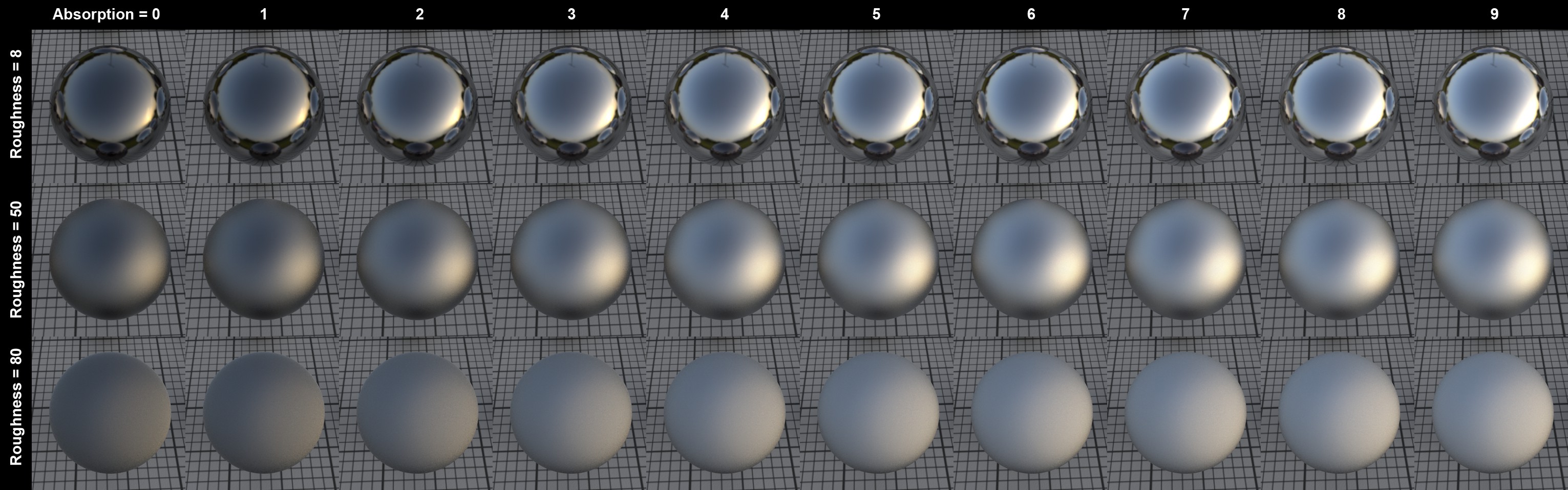 The Absorption effect in conjunction with Roughness (IOR = 2.97).
This setting is only available for the Conductor mode. Increasing values will produce correspondingly stronger overall reflections. This setting can be used to fine-tune the degree of reflection.
The Texture setting can be used to apply the previously described setting to an entire texture. The grayscale values of the texture loaded here control the setting as follows: white represents the setting’s full value and black = 0. In-between gray values have a corresponding effect.
Layer Sampling
Sampling Subdivisions[0.00..16.00]
This setting is designed for use with the Standard Renderer only (i.e., not the Physical Renderer). It can be used to define the quality of matte reflections.
Larger values will slow rendering and increase quality correspondingly.
It can occur that a reflected HDR image/sky can produce extremely bright points (fireflies) on a third object - i.e., a reflection of a reflection. To prevent the sampling settings from being increased dramatically, this setting can be used to limit the intensity of this reflection. The higher the value, the more the intensity of the reflection will be restricted, thus reducing this effect.
This is a threshold value that defines the degree to which weak reflections will be calculated, if at all. Let's say you have a Project with numerous reflective objects. An object at the rear of the image that is reflected in a small object near the front can be omitted because its role in the overall image is so small. The smaller this value is, the more reflections that will be ignored. The image below is an example of how this setting can be applied (the very bright HDR image helps make the effect more pronounced):
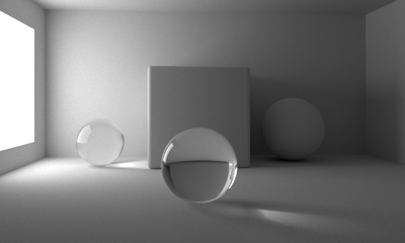
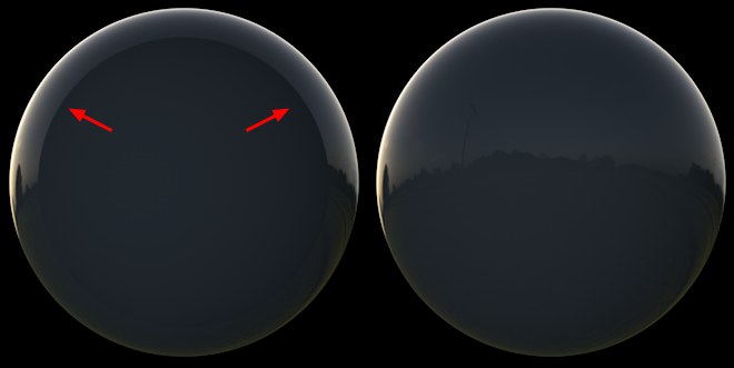 If the effect at the top left takes place, then the Cutoff value needs to be reduced.
A sphere with a Fresnel reflection reflects a HDRI sky. The Cutoff value on the left is too large; the corrected value is on the right.
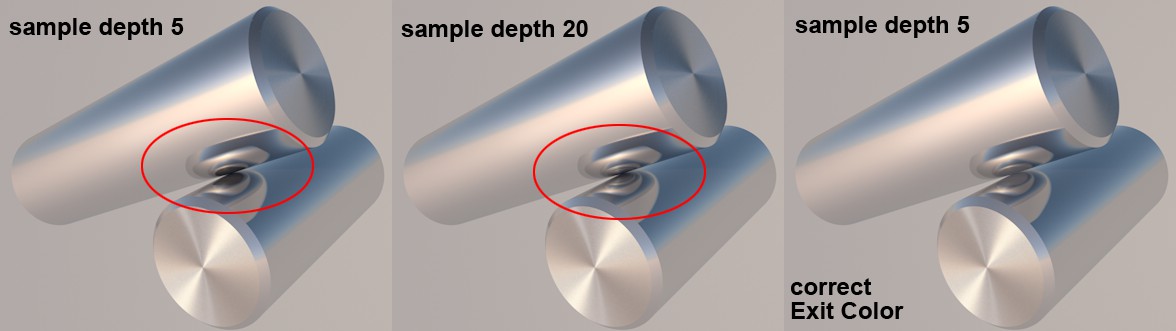 A fitting exit color is used to create a realistic-looking result without increasing the diffuse depth.
A reflection depth can be defined in the Preferences menu that defines the number of reflections that should take place. For example, if you have two mirrors facing each other, this setting can be used to limit the number of reflections that take place. Otherwise an endless number of reflections would be rendered with a more-or-less endless amount of render time. The Exit Color setting defines the color the reflection should assume in the end. In previous versions of Cinema 4D, this was black by default. However, as you can see in the image above, this produced unwanted black spots. This can be avoided if a fitting color is defined for the last reflection, as can be seen in the image above).
Reflections can be split for Multi-Pass rendering so that only certain materials are output in separate passes. To do so, this option must be enabled (details can be found here).
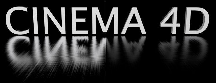 Left without, right with Distance Dim
Contrary to what the real world, this setting can be used to omit objects from a material's reflection depending on their distance from that material. If Distance Dim is disabled, all objects will be reflected. If enabled, the Distance value defines the distance at which an object will no longer be reflected. The reflection falloff up to the Distance value is defined using the Falloff value. A value of 0 produces a linear falloff; other values produce the effects shown in the example above.
The reflection of the Sky object was disabled because it is considered to be an endless distance away.
For this setting, imagine a sphere with a Distance radius around the reflective object. This sphere's color is reflected when the reflection samples are longer than the Distance value defined. Normally, black would be the correct color in this case because it would prevent anything from being reflected. Other colors can be used depending on the intended result.
Transparency tab
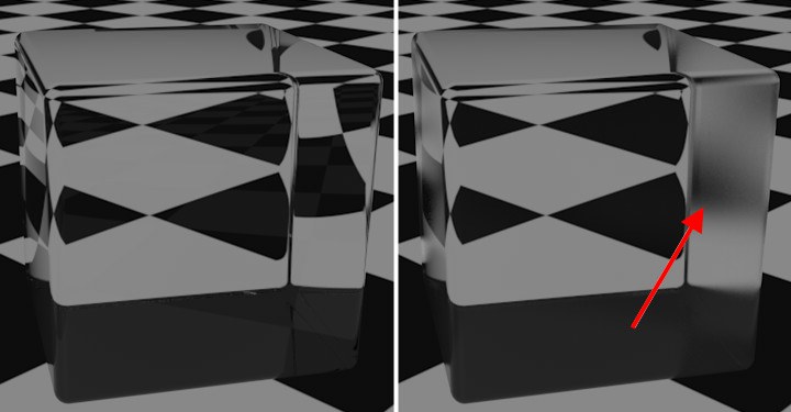 The Total Inner Reflection is also part of the Reflectance channel; the Roughness was increased on the right.
A Transparency will be added when the material channel Transparency is enabled. This tab contains reflection settings, however without Color or Mask settings, among others. The settings in this tab let you control the inner total reflection's reflective properties.
Normally, these settings do not have to be modified. If you're not trying to achieve a very unusual effect, these settings can be left as they are.
This tab cannot be copied or deleted.