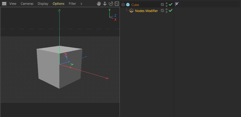
 With a Nodes Modifier Group, geometries can be edited directly in the Object Manager.
Here you can find various data types and data formats that can be used to easily add ports to assets and groups. If necessary, these ports can be customized in their interface, order with regard to restrictions via the Resource Editor. We will therefore also take a look at working with the Resource Editor in this section.
Below are explanations of typical steps for using these elements and how you can use them to create your own assets.
For more information and examples on how to use assets and User Data, see the description of Asset Construction Nodes.
Quick access:
In this example, the goal is to develop an asset that adds extra detail to an arbitrary geometry by randomly selecting parts of the surface, extruding them, and rounding them in the process. Functions like these can be created with just a few Nodes. Creating a dialog, on the other hand, can be more challenging so that the asset's functions can be easily controlled without the Node Editor. There are several options for this, all of which we will look at.
However, let's start with the first step, calling a Nodes Modifier Group from the Asset Construction Nodes in the Asset Browser. From there, drag the Nodes Modifier directly into the Object Manager. There, this entry then works like a deformer, so it must be subordinated to objects. Therefore, create a simple promitive directly, such as a cube, and assign the Node Modifier directly to it. Since this has not yet been filled with functions, nothing will change about the cube for now.
By the way, you can also use the Nodes Selection Group according to the same principle, except that it is mainly used to manipulate or create point, edge or polygon selections on the parent object.
 With a Nodes Modifier Group, geometries can be edited directly in the Object Manager.
To view and edit the content of the Nodes Modifier Group, the Node Editor must be opened (see image below). To do this, you can either switch to Cinema 4D's Nodes layout or open the Node Editor from the Window menu. If the Nodes Modifier entry is selected in the Object Manager, the Node Editor should automatically open in Capsule Mode and therefore display only the contents and inputs and outputs of this Asset Construction Node. You can also make this switch manually at any time using the Node Editor's Mode menu (see number 1 in the image below).
Next to the number 2 you can also read the name of the currently displayed asset capsule, so in our case Nodes Modifier. In addition, it can be helpful to directly show the Asset Browser and the Attribute Manager at the left and right edges of the Node Editor (see number 3 in the image below). This way you can maximize the Node Editor, which can be helpful when processing complex setups.
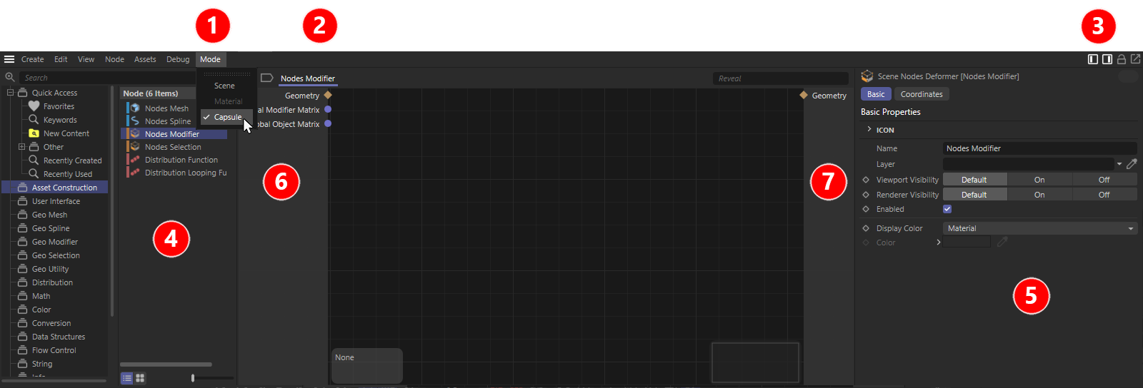 The various elements of the Node Editor in Capsule mode.
If you've activated the two icons at number 3, the Asset Browser (see number 4) will be visible on the left and the Attribute Manager (number 5) on the right. Between these areas lies the actual Node Editor, which is framed on the left by the input area (see number 6) and on the right by the output area (see number 7) of the selected Nodes Modifier Group. For us, the Geometry inputs and outputs are particularly interesting. The Geometry input on the left provides the geometry of the object to which the asset construction group was subordinated in the Object Manager. This is the cube in our case.
This geometry can now be processed by us within the setup. The result will be a modified geometry that must then be routed to the Geometry output of the group to replace the original cube.
 Add a first function to the Nodes Modifier Group.
To evolve our Nodes Modifier Group into a functional asset, just adding a single Node that can handle geometry is enough. You can find a large number of these Nodes in the Geometry Modifier Group of the Asset Browser. We select the Subdivide Node there and drag it from the Asset Browser directly into the Node Editor.
On the left side of this Node you will find the input for a geometry to be processed (digit 1 in the image above). Simply create a connection between the Geometry input of the group and the Geometry input of the Node by dragging a connecting line with the mouse. In the same way, you establish a connection between the Geometry output of the Node (see number 2) and the Geometry output of the group. Afterwards, you should already be able to see a change in the geometry. If necessary, switch to the Gouraud Shading (lines) display in combination with wireframe in the Viewport to have the edges of the object displayed as well (see the following image).
In our case, the cube will be subdivided further. Which kind of selections are to be evaluated (points, edges or polygons) or how often the object is to be subdivided, for example, can be set after selecting the Subdivide Node in the Attribute Manager (see number 3 in the image above).
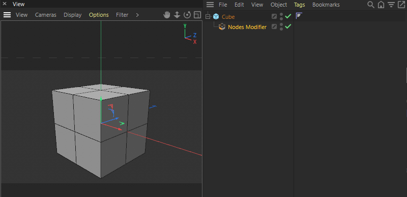 The modified cube after adding the Subdivide Node to the Nodes Modifier Group.
Nodes, like the Subdivide Node in our case, provide many settings in the Attribute Manager, some of which may also be of interest to users of the Nodes Modifier Group. The only annoying thing about this is that you always have to select the corresponding Node in the Node Editor before you can edit its settings in the Attribute Manager. There is a solution for this problem, because any settings can also be created as input ports on the Nodes and then linked to the input page of the group. We will do this here first for the Type setting of the Node for selections, so that a user can later select which selected elements (points, edges or polygons) should be used to constrain the Subdivide function.
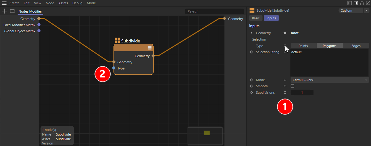 Adding a parameter as an input port via the Attribute Manager.
The image above depicts this process. First, select the Subdivide Node to view its settings in the Attribute Manager. In the column marked with the number 1 in the image you will find small circular symbols. Cmd/Ctrl+clicking on one off these circles makes the corresponding parameter directly visible as an input port on the Node. Try this with the Type parameter. As seen in number 2, we get the desired Type port on the Node. This port must now be connected to the group's input side to be visible to a user of the Nodes Modifier Group. For this purpose, a port must also be created in the input area of the group.
The creation of a group input matching the Type Node input can be created by a simple drag and drop action. This is shown in the image below.
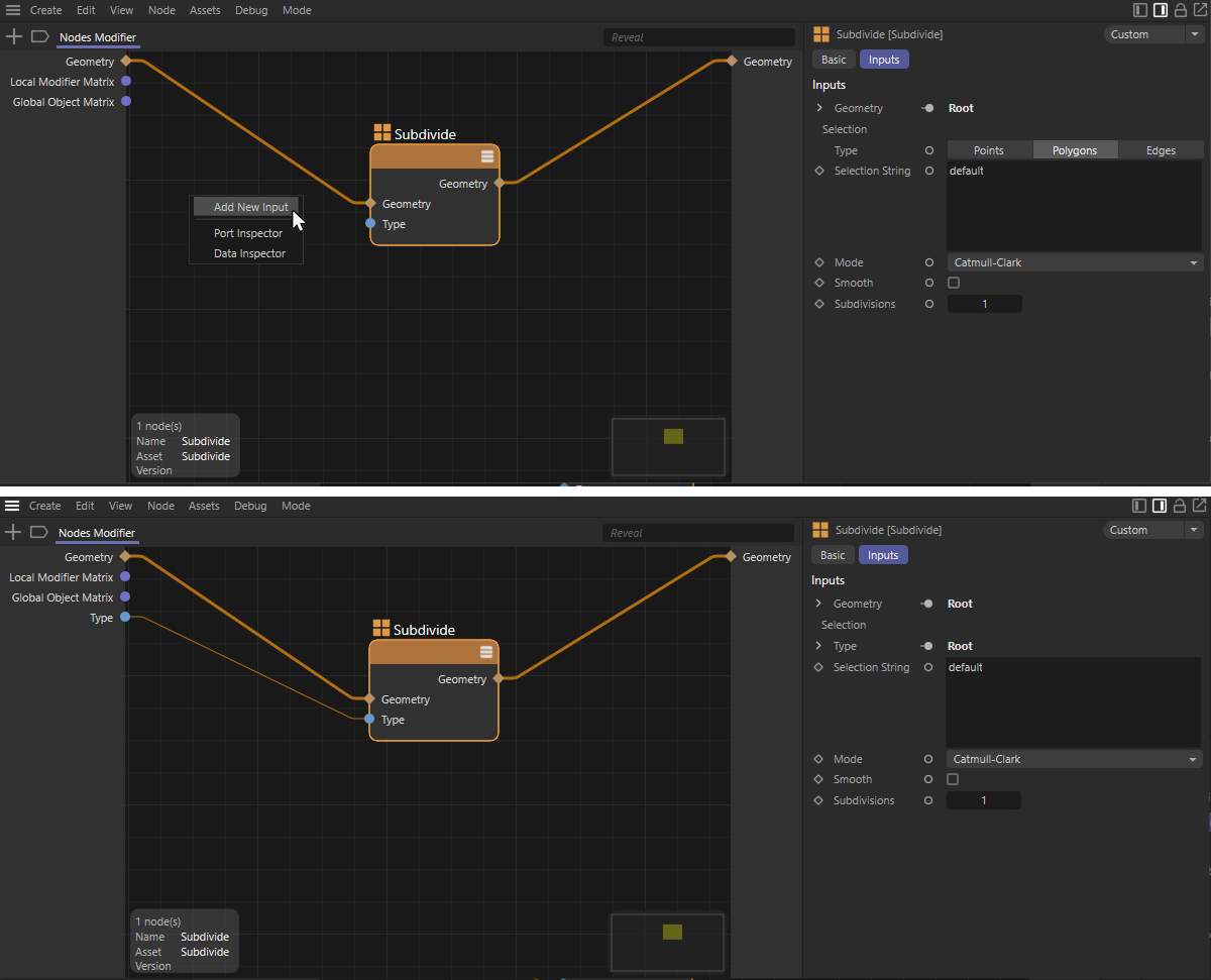 Create a new group input.
Draw a connecting line from the new Type input of the Subdivide Node to the left input area of the group and release the mouse button there. A small context menu will appear where you select Add New Input. As you can see in the lower half of the image above, this creates a new Type input on the group there, which is automatically connected to the Type input of the Node. As a result, the Type setting is no longer available in the Attribute Manager. You can see this on the right side of the image above, where the options for Points, Edges and Polygons are now unavailable.
The advantage of these steps is that you do not have to worry about the data types of the ports. The data type and user interface of the original Node parameter is automatically adopted.
Let's check this directly. Select the Nodes Modifier Group in the Objects Manager and take a look at the Inputs tab in the Attributes Manager. There you should now be able to view and operate the Type option directly (see image below).
 Depiction of the new control element of the group in the Attribute Manager.
Of course, you can also rename this new control if you like. To do this, double-click on the name of the new group input in the Node Editor and simply enter the new name there. For example, we use the term Restrictive Selection Type here so that a user understands directly what they are doing with this setting (see number 1 in the following image).
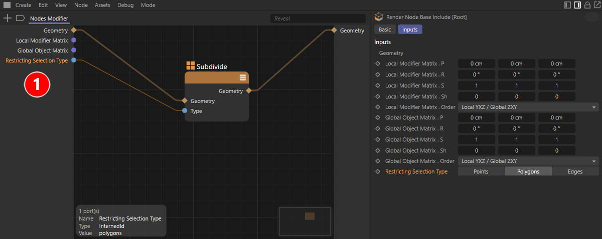 Depiction of the new control element of the group in the Attribute Manager.
However, new controls for users can also be created independently of existing input ports on Nodes. This can be helpful, for example, if you want to offer a special data type or a control element that is not offered by default at the Node to be connected. For example, you can use an input first for mathematical calculations before the result is then passed on to other Nodes.
In our example, this way the number of subdivisions should be able to be controlled by the Subdivide Node. Since this is an integer value, only the Integer control can be used for this. In the entries for the user interface elements of the Asset Browser you will find these entries:
In principle, all three elements are suitable for our purpose, although only small, positive values are generally useful when defineing subdivision levels. We will also learn how to check the plausibility of the values entered by the user before they are used in the setup, or how to limit them automatically, if desired.
In our case, we keep it simple and will drag the entry for IO Integer from the Asset Browser into the Node Editor. A new input for integer values is automatically created at the group. This can again be renamed as desired by double-clicking, e.g., with Basic Ssubdivisions (see number 1 in the following image). This is used to select the subdivision levels before the geometry is then processed further.
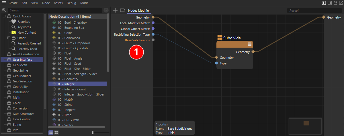 Manually create and rename a new input port on the group.
As with the connection of the Type setting, we again need a suitable input at the Subdivide Node, this time for the number of subdivisions. To do this, select the Node and Ctrl+click on the circle icon next to the Subdivisions value in the Attribute Manager (see number 1 in the following image). The corresponding input on the Node appears (see number 2).
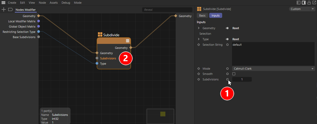 Add the required Node input.
Alternatively, you can add new inputs directly at the Node. To do this, right-click the Node and select Add Inbox from the context menu. However, for Nodes that provide many settings, it can be laborious to find the correct port name. Therefore, the Cmd or Ctrl+click method described above is preferable in many cases.
Finally, make the connection between the new Base Subdivide port on the group and the Subdivision input on the Node by dragging with the mouse. After selecting the Nodes Modifier Group in the Object Manager, the Attribute Manager displays both user settings. By gradually changing the value for the basic Subdivisions, you should be able to directly observe how the cube is additionally subdivided to a greater or lesser extent. The only thing that might be a bit annoying is that this value is displayed above the selection option for the selections (see the following image). Therefore, let's now explore how you can influence the order of User Data.
 Checking the User Data in the Attribute Manager.
The use of IO elements from the User Interface group can be used not only for assets, but also for normal Node groups to add individual inputs. The only difference here is that by default (unless it already contains Nodes that receive values from outside), an open group does not display an input or output range. The gray areas on the left and right edges of an opened group may therefore still be missing initially. These are created automatically when you create new ports on the group. The images below illustrate this.
 On the left you can see an empty group in the Node Editor. By default, this has no inputs or outputs, as is also clear on the right when you look at the group.
 On the left, an IO Geometry input was first dragged from the Asset Browser into the group, and this new input was then connected to an Extrude Node. To add a matching output to the group, drag and drop the Geometry output of the Node and then select Add New Output. On the right you can see the group completed by ports.
New inputs to a group can be added either by dragging an entry from the User Interface group of the Asset Browser or - if there are already Nodes in the group - by dragging and dropping from a port input into the empty Node Editor and selecting Add New Input. The same can be done with output ports of Nodes to add outputs to a group. This can be seen on the left side of the image above.
Another option for adding and configuring ports is provided by the Resource Editor, which is described in the next section.
The order of the ports can be changed directly at Nodes and also at the group inputs and outputs via drag&drop. This is helpful, for example, when fixing crossing connector lines. While this does not matter for the functions themselves, it can help improve the clarity of the setup. However, this does not change the order in which the group inputs are presented in the Attribute Manager. Although this primarily depends on the order in which the inputs were added to the group, there is a solution for this as well: The Resource Editor.
To open it for the current setup, right-click in the Node Editor and select Edit Resource ... from the context menu (see the following image).
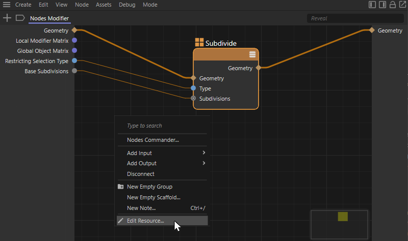 Open the Resource Editor for the group.
Of particular interest to us is the left column of the Resource Editor, which lists the current inputs and outputs at the asset in the upper part (see number 1 of the following image) and displays the available options for additional inputs below (see number 2). These options are identical to the Asset Browser User Data we already used to create the IO Integer input.
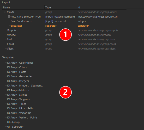 The left column of the Resource Editor
You can also use the Resource Editor to create the desired inputs to the asset group directly. To do this, simply drag the desired entries from the lower list (see number 2 in the image above) directly under the Inputs entry in the upper port listing (see number 1). Here, too, the ports added by the user can be renamed individually by double-clicking.
The order of the entries in the Inputs group automatically reflects the order of the parameters in the Attribute Manager. You can now re-sort accordintly. In addition, it is also easier here to drag the elements to be arranged, UI - Group and UI - Separator from the lower list directly to the desired places in the upper hierarchy. This then allows subcategories (UI - Group) and simple separators (UI - Separator) to be included for structuring more extensive parameter lists.
The UI - group works like an order element, which you can give a group name and sort other inputs in the Resource Editor under it.
When re-sorting, make sure that the Basic Subdivisions are displayed only after Restricting selection type and finish these settings with a UI - Separator element(see number 1 of the image above). Then close the Resource Editor. The changes will be applied automatically.
There are parameters that become relevant only if specific setings are used. Think, for example, of the Maximum Angle setting of many modeling functions, which can only be used after activating the Preserve Groups option. If you want to make the setting for Maximum Angle available to the user of an asset group, for example, remember to either also bring out the associated option for preserving polygon groups, or make sure within the setup that Maximum Angle can also always be used.
As the following image shows, it may also happen that parameters that are already organized in groups at the Node are also displayed in subgroups in the Resource Editor and not under the Inputs group.
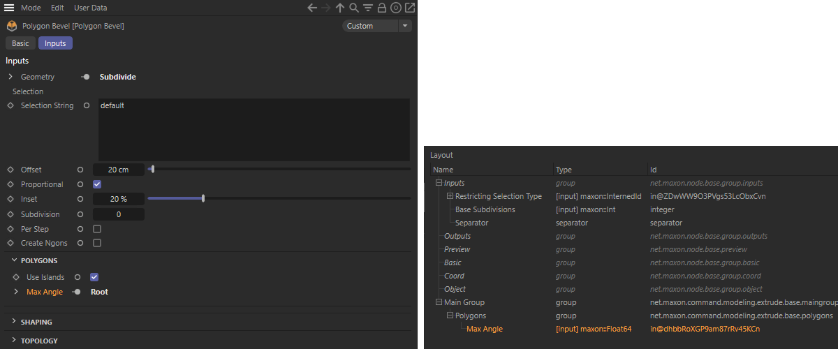 Grouped parameters automatically appear in subgroups
Depending on which properties or functions you want to control in a setup by user input, customizing the controls of a parameter and defineing a default value or limits can be useful. All these tasks can also be done in the Resource Editor. To do this, open the Resource Editor for the asset that carries the User Data and select the Input value you want to edit in the upper left list area of the Resource Editor. We have already seen in the previous section that you can also customize the order of inputs in this area and that groups or separators can also be inserted here (using the UI - Group and UI - Separator elements). However, to edit the interface of a parameters, take a look at the center column of the Resource Editor.
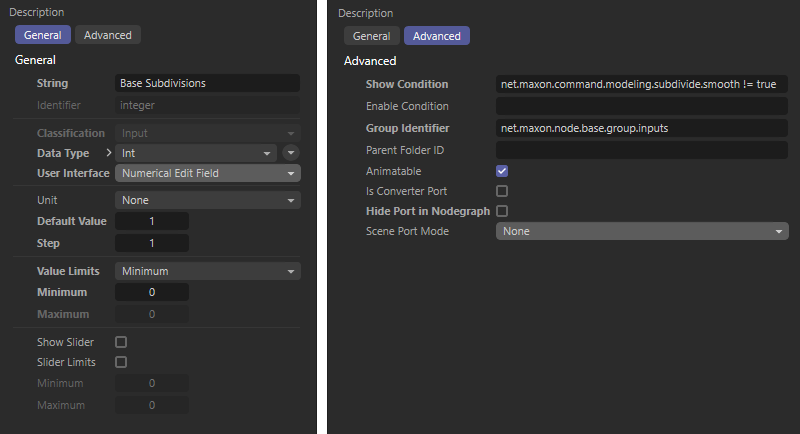 General and Advanced Settings for a Selected IO - Integer Element in the Resource Editor
As can be seen in the image above, two pages of settings are available, General and Advanced, with the General settings already containing the most important functions. We will go through these in order:
As you can see from the above setting options, it is also very easy to add subsequent sliders to simple IO - Float parameters or, for example, to limit or adjust the values allowed for input.
Let's also take a quick look at the Advanced settings in the Resource Editor.
In many cases it makes sense to check or convert entered values, e.g., not to allow too high inputs for the Subdivisions, which could cause memory problems. Also in other cases, for example, when percentage values are entered via an IO Float - Strength - Slider, these can then be converted into other numerical values for further processing. As you can read in the section above, such limits for value input can be specified directly in the Resource Editor for each parameter that is waiting for a number input. Sometimes, however, such limits have to be converted directly in the setup, e.g., for certain mathematical calculations. Therefore, in this section we will look at how you can convert numbers or restrict them to the desired range of values.
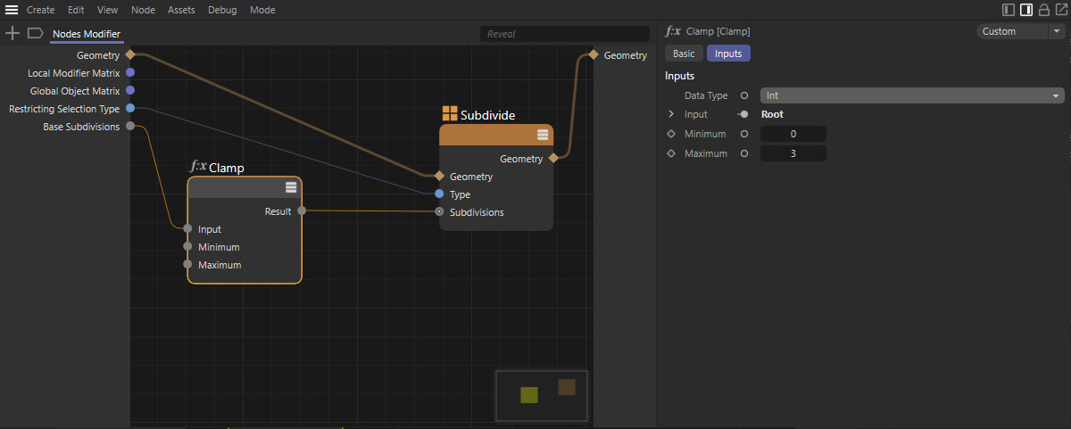 Input limitation
The first Node that lends itself to this is the Clamp Node, which you can find in the Math category of the Asset Browser. Connect its Input port to the Base Subdivision port of the group once as a test and then connect the Result output of the Clamp Node to the Subdivision Input of the Subdivide Node. Since each Input port can only have one connection, this automatically deletes the old connection. Otherwise, you can also have the old connection removed by double-clicking on it before connecting the Clamp Node.
The Clamp Node now first offers a Data Type in the Attribute Manager that should correspond to the value you want to get at its Result output. So this should be Integer (abbreviation: Int) again.
The specifications for Minimum and Maximum refer to the range of values you want to allow as a maximum. Even if the Input value is less than the Minimum value, only the value of Minimum will be output. Accordingly, the maximum value of Maximum will be output, even if much higher values are entered.
This Node is also in the category of Math Nodes. This Node can be used to convert value ranges. For example, if values between 0% and 100% are entered, values between 0.0 and 5.0 can be output. The values for Input Min and Input Max define the range of values between which permissible user inputs should lie. The Range Mapper does not restrict these maximum values itself. You can therefore again connect a Clamp Node in front of the input of the Range Mapper Node so that only values between the Input Min and the Input Max are processed. The following image shows an example of this.
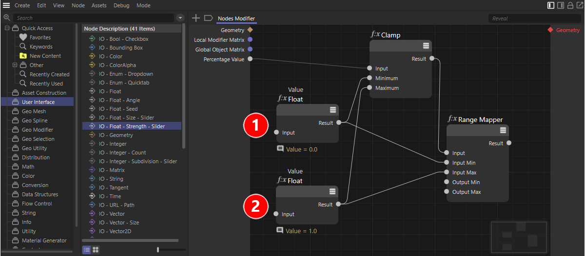 Use of a Range Mapper Node
In the above example, a percentage value is used as the input of the group via an IO Float - Strength - Slider. If, for example, only inputs between 0% and 100% are to be allowed there, we can connect a Clamp Node as in the previous example. Percentage values are treated internally as floating point values, where 100% corresponds to the value 1.0. We must therefore use the value 0.0 for Minimum (see number 1 in the image above) and the value 1.0 for Maximum for the Clamp Node(see number 2). In our example, we do not enter these values directly at the Node, but use Value Nodes for this, which you can also find in the Math section of the Asset Browser. This Node simply provides the same value at the Result output that was entered at the Node. This is always useful when identical values are to be used on multiple Nodes. In that case, this value only needs to be edited once at the Value Node and is then directly available at all Nodes connected to it.
In our case this affects the two already mentioned inputs for Input Min and Input Max at the Range Mapper Node. So make the appropriate connections between these inputs and the Value Nodes. A fixed input range has been defined and you can concentrate on the values for Smallest output and Largest output, which you can enter directly at the Range Mapper. The calculation of the Result output will then take place according to the classic rule of three. The inputs between 0% and 100% can then be automatically converted to the values between Smallest output and Largest output.
In some cases it can be helpful to simulate a looping behavior for values. Imagine, for example, angle values that are automatically converted to the value range between 0° and 359.999°, even if they are below 0° or above 360°. Unlike hard limiting of Input values, such as with the Clamp Node, increases or decreases in an Input value then continue to result in adjusted new values, but these are also between fixed limits. The angle input 400° then leads, for example, to the result value 40°, since full 360° rotations subtracted from 400° result in a residual angle of 40°.
This math function exists as a Modulo Node in the group of Math Nodes.
 Various examples for the calculation of a Modulo Node
As shown in the image above, the Modulo has two inputs. At the lower input, always enter the maximum permissible value. If you want to limit angle values between 0° and 360°, for example, enter 360. The Modulo generally works with a lower limit of 0, i.e., only allows values between 0 and the value of the lower input as a result.
When processing angles, note that many Math Nodes expect angles in radians. 360° correspond to the value 2*pi. For this conversion, use the Angular Unit Node from the Conversion Node group.
At the upper input, for example, you pass the value defined by the user to the Modulo Node. At the Result output you will then always get values that lie between 0 and the value of the second input. With reference to the examples in the image above, the results are created as follows:
The value at Input 2 is generally used positively, but the value at Input 1 may also be negative. In our example with the angles, an input of -400° would therefore lead to the Result -40°.
Often, a user's input can be used at multiple locations within the Node setup. For this reason, the inputs of a group or an asset can also be connected to several inputs of a Node or different Nodes at the same time. Depending on the position of these Nodes in the setup, however, it can quickly become confusing if connections criss-cross a setup. In such cases, it may help to detach input ports. Here is a simple example.
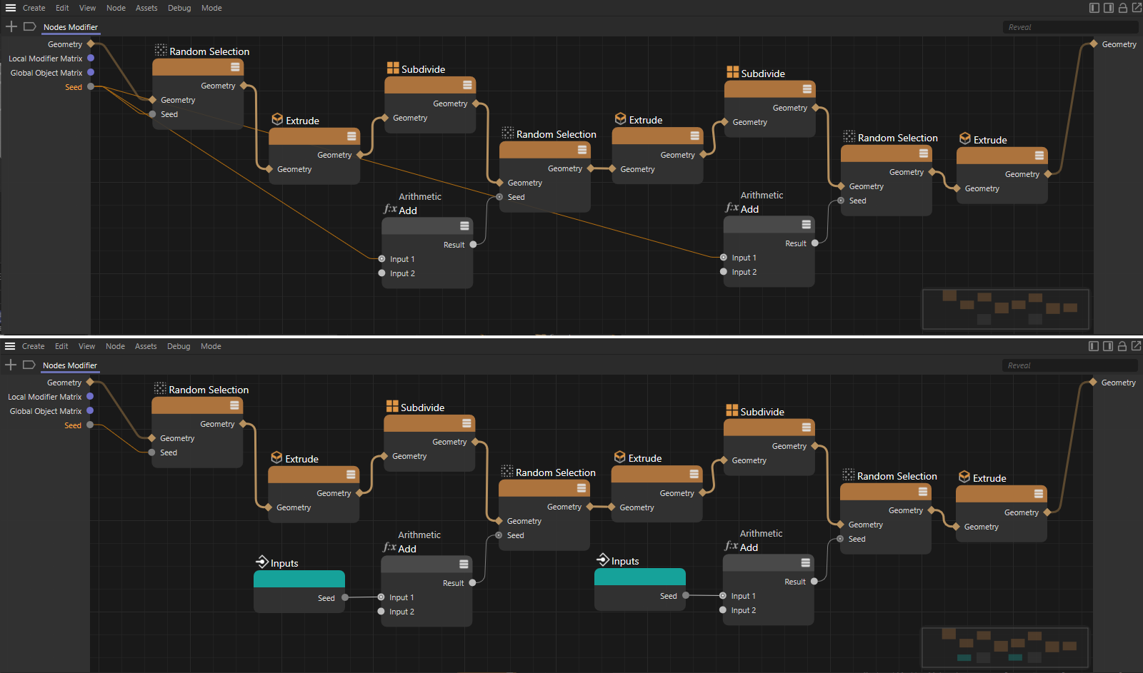 In the setup above, an integer value is used multiple times in the setup to set different initial values for random functions. Below you can see the modified setup where the Start value input is used directly at the corresponding Nodes. This eliminates the long connections to the left input side of the group.
As seen in the example above, the readability and clarity of the setup is improved by using the Input values directly at the Nodes where they are processed. To do this, simply drag the name of the corresponding input from the left edge of the group into the setup. A special Node type will be created, which provides the value of the corresponding input. Any number of these Floating IO Nodes can be created in the setup.
With a few additional Nodes we can now complete our setup and get an interesting result with it. A Noise selection will create a random selection of polygons on the subdivided object. To do this, create the Threshold and Invert option as user inputs to the group.
You pass the result of the Noise selection to a Polygon Bevel Node to extrude these polygons, scaling them as needed. Here you can, for example, output the values for the Offset and Extrude Inside functions.
Compare the result of a newly created Node with the geometry of the Noise selection. This will give you a selection containing only the new polygons created by Polygon Bevel. Finally, if you pass this Polygon selection to another Subdivide Node, which this time also has the Soft option enabled, its rounding subdivision will be limited only to these new areas of geometry. Connect the output geometry to the Geometry output of the group to be able to view the result of the calculation in the Viewports as well.
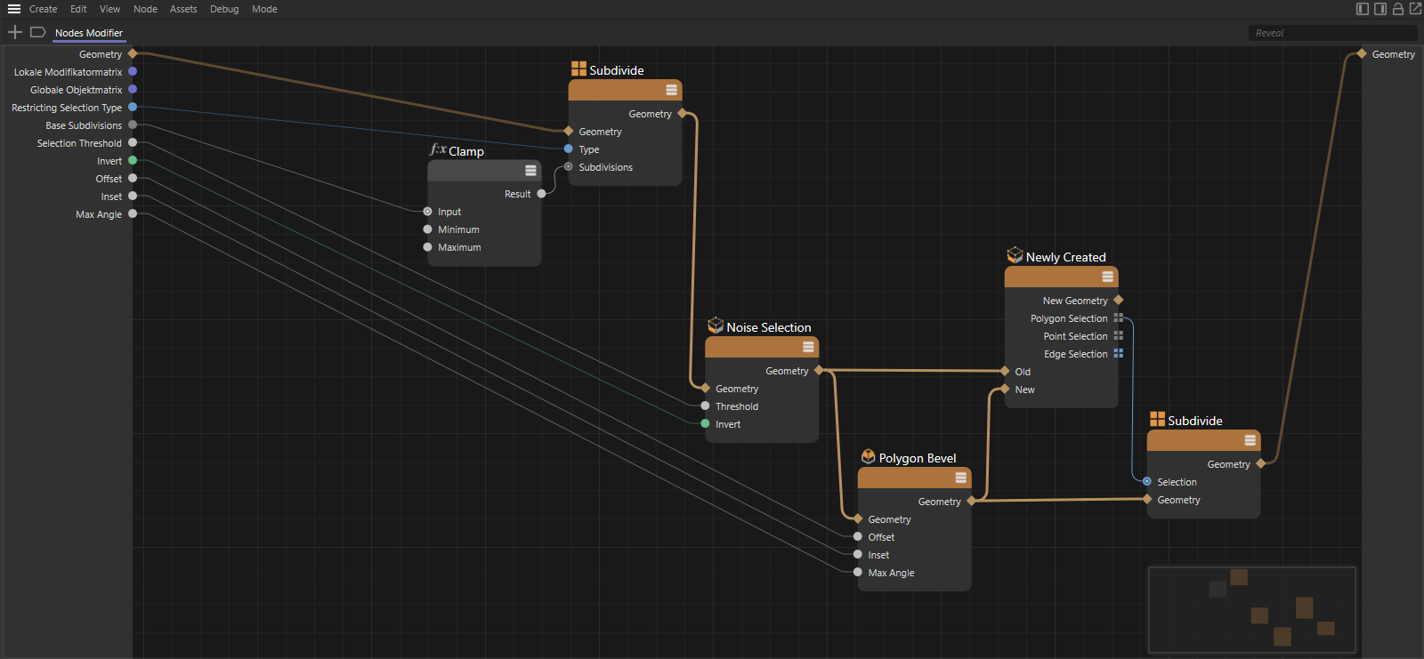 The finished setup of the Nodes Modifier Group
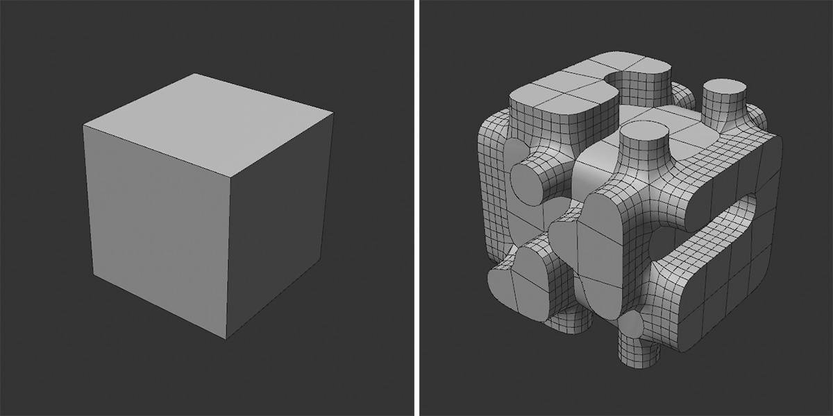 The effect of the above setup on a simple cube
Below you will find a complete listing of all IO elements that you can use for assets or even groups in Node setups to define individual inputs and outputs.
These elements are useful when you want to provide users with a drop-down menu or multiple modes as buttons. By default, these elements each have three selection options, which you can rename as you wish in the Resource Editor. Both IO elements return integer values starting at 0 for the first list element. You can have these values converted to any other values, for example, with a Switch Node.
 The two enumeration elements in the Resource Editor compared. On the right-hand side you can see how the operating elements differ.
This lets you add an individual output port, e.g., at a group. The Data Type of this output is not yet defined, but can be set individually via the Resource Editor.
This element provides a simple option or checkbox, e.g., to enable or disable a function. The output can be used as a numerical value, where 0 is output when disabled and 1 when enabled. At the same time, however, the results can also be interpreted as false (disabled) and true (enabled) and thus evaluated directly with a Boolean Operator Node, for example.
This is a special vector data format intended exclusively for transferring the aspect ratios and size of a bounding box. For this reason, this element does not provide a user interface. This element could, for example, be connected with the Bounding Box output of the Node with the same name.
Two elements are available for entering and passing on color information, IO - Color and IO - Color Alpha. These are basically identical, except that IO - Color Alpha includes an additional percentage value to determine the opacity of the color. Both elements provide vector data where the components X, Y, and Z represent the color components red, green, and blue and are stored as floating point values between 0.0 and 1.0. IO - Color Alpha includes an additional alpha component whose value can also LIE between 0.0 and 1.0. Both data types can be read and processed as Color or ColorAlpha, as well as Vector3d or Vector4d.
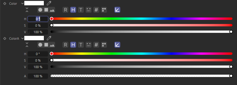 A comparison between the two IO Color elements.
Floating point values, i.e., numerical values that also have a decimal part, such as 3.4151, are particularly flexible for use in mathematical calculations or when values need to be entered precisely. This data type can also be linked to units, for eample, to represent percentages, angles or dimensions. Therefore, different variants of this data type are available. In all cases, however, you get simple numerical values. Only the displayed units and controls differ. In addition, some of these elements are already limited to a number range, so that under certain cirucumstandes non-arbitrary numbers can be entered.
This data type is specifically intended for the exchange of information related to the geometry of an object. This includes, for example, the point positions of a surface or a spline, the point pairs that are connected to edges, the points that bound polygons, or the tangents of a spline. Due to the complexity of this data type, no control element is provided. Instead, you must use the Geometry ports of the Nodes to pass or accept data on that port.
With these elements, integer values can be exchanged. Use this data type only if you do not intend to perform more complex calculations with these values. Otherwise the data type IO Float can be used. Integer values are useful e.g., to define a number of subdivisions or copies.
A matrix consists of various vectors by which, among other things, the position, size and rotation of an axis system or object in space can be defined. This control is therefore identical to the Coordinates section for objects.
 The different vectors of a matrix contain the position of an axis system, as well as the rotation angles, the axis lengths (size) and the shear of the axes. Use the Matrix.Sh component only if you want to influence the perpendicularity of a typical axis system.
These entries are of interest if you are working with the Node Mesh Asset and want it to access objects in the Object Manager that are sorted under it. Capsules can then be created that function like a classic generator object, e.g., like an Extrude or a Subdivision Surface object, to which the objects they are to work with must also be subordinated. To be sure which object type has been grouped under the capsule - e.g., if modeling commands are only used for polygons and not for splines - the Geometry by Type Node can be used within the capsule.
The following variants of the IO Object Input are available:
 Here, two IO object Child object inputs were created on a Node Mesh in order to be able to process the two subordinate objects in the Object Manager in the capsule circuit.
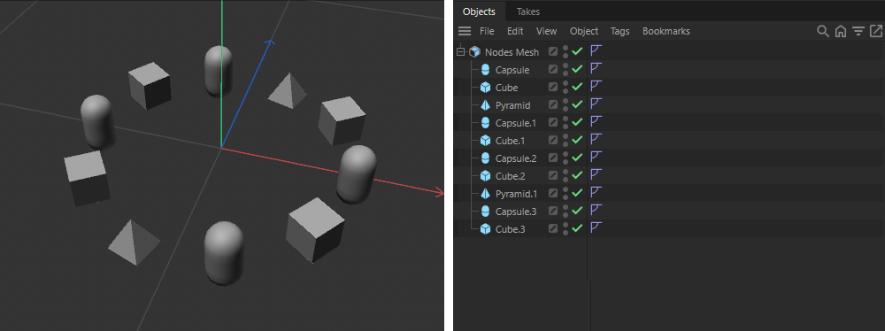 All objects subordinate to the Node Mesh are distributed evenly in sequence on a circular curve and aligned tangentially to it. The function automatically adapts to the number of Child objects.
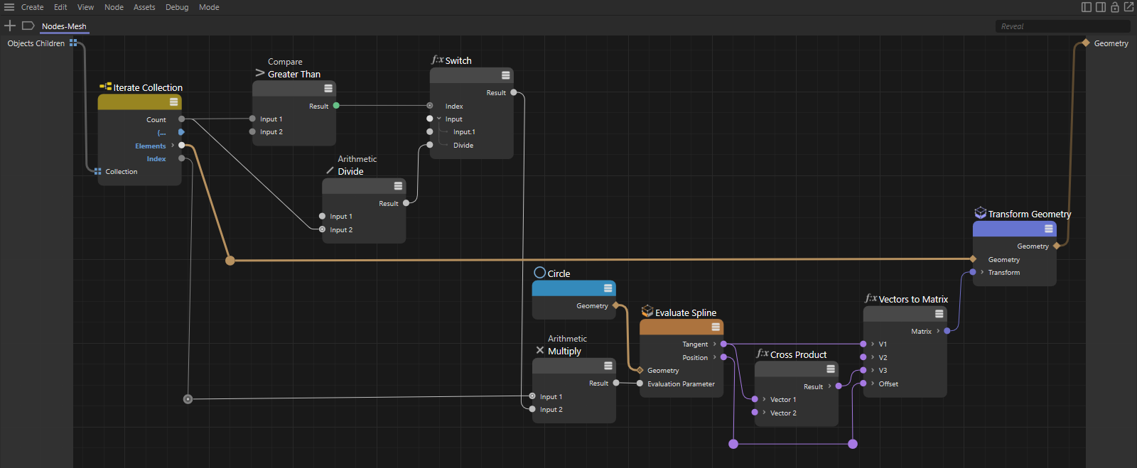 A Collection Iterate Node can be used to output all Child objects in sequence and make them available in the circuit. The total number of Child objects and the index of the currently output object can also be queried there.
Regardless of whether you only want to work with individual Child objects or entire lists of Child objects, you should always check the type of the Child object you have just read and whether it is compatible with the functions to be used before processing these objects, e.g., with mesh, line or spline functions. For example, different Nodes are used for rounding edges on a mesh than for rounding points on a line geometry. The Geometry Info and Geometry by Type Nodes, for example, are available for this purpose.
It should also be noted that spline Child objects of a Node Mesh asset within the asset are output as line geometry and not as a spline.
You can also find further examples of processing Child objects on this page on the use of assets.
 With IO - Object links, a linking field for objects can be added to the Node Mesh, which the user can use to link any objects that do not have to be in a hierarchical relationship to the Node Mesh.
This is a special input type for the particle groups of the particle system. This gives you access to the group name and the group index of a particle group, which can be defined via a link field. You can use this on a Particle Node Modifier, for example, to access the IDs or names of specific particle groups.
This is a special data format(Tuple) through which two vectors can be transmitted simultaneously. This data type is intended for the control of a tangent pair. Each vector controls the direction and length of a tangent at a spline point (applies only to Bezier splines). This data type has no user interface and is therefore only intended for connecting Nodes that provide tangent information.
This element provides a string Input field through which, for example, names for an object or a saved selection can be entered.
As with the IO- Text element, a field is provided here for a string input. In addition, you will find a folder icon to the right of the text field, through which you will open a file dialog. In this way, any directory can be selected, e.g., for loading or saving data.
Vectors consist of several floating point values, by which then e.g., a RGB color value, a position in space or a direction vector can be described. The following vector elements are available:
This element provides an Input field for a frame number to define a point in time within an animation. Such information could be used, for example, to execute a function or calculation only from a specific point in time.
Under this term you will find the various data types that have already been described above as individual elements. The difference here is that IO - Arrays cannot provide a user interface. An array corresponds to a variable length list. Several values of a certain data type can be stored in this way. For example, think of an IO Array - Vectors - Points, through which all point coordinates of a geometry can be stored.
Arrays can, for example, be created with a Build, a Set Array or a Fill Array Node itself and filled by adding values. In general, most of the Nodes that handle array values can be found in the Data Structures group of the Asset Browser.
Since all IO - array data types do not provide a direct interface for the input of values, these IO elements are mainly interesting for ports which are responsible for the input or output of arrays to groups. Below is a simple example of how to create and output an array.
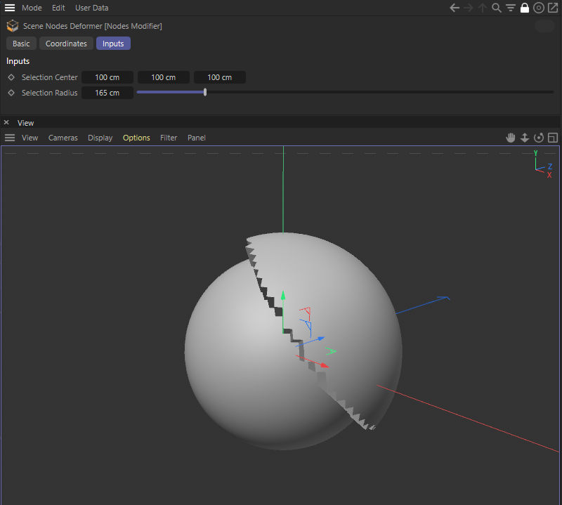 In this example, a Node Modifier group is used to extrude the polygons that lie within a selection radius around a global position (selection center).
As you can see in the image above, we created User Data for IO - Vector - Size and IO - Floating Point - Size to be able to define a position and a radius value at a Nodes Modifier Group. The effect of the asset should be to automatically select and extrude all polygons whose points lie within a sphere radius around a given position. Technically, we implemented this as shown in the following image:
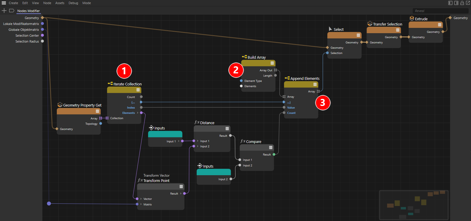 The complete setup for defining and implementing an individually created selection
We use a Read Geometry Property Node with the Type setting 3D Points to get an array with all local point positions of the supplied geometry. This is an array of 3D vectors. To be able to output an array entry by entry, a Iterate Collection Node(see number 1 in the image) will be connected. This turns the array into a data stream that provides all elements of the array one after the other. This way you can generally output all elements of an array in order.
The individual vectors of the output array represent the local point positions of the geometry and can be converted to global point positions by multiplying them by the global matrix of the object from which the geometry originated. The Transorm Vector Node is used for this purpose. The distance between the point converted in this way and the default selection center is calculated with a Distance Node and compared with the selection radius using the <= function. If the calculated distance is less than or equal to the default, the Compare Node returns the value 1 (or true), otherwise the value 0 (or false).
Via a Build Array Node(see number 2) we can define a new array of the data type Integer, so that we can retain in it the numbers of the points to be selected. By clicking the Truncate button on the Build Array Node, we can remove all entries to create a completely empty array. By means of a downstream Append Elements Node(see point 3), integer values can now be added to the array. The number of entries in the array increases automatically by the Count value. If the Result of the Compare Node is connected there, the new array is always extended by one entry only if a point was found within the search radius(Result = 1). The index number of this point is thereby added to the array (see Connection between the Index output of the Iterate Collection Node and the Value input of the Append Elements Node) . In this way, a selection array is created that can be used wherever. For example, modeling functions can be restricted to a selection.
In our case, at the end only the point selection has to be converted into a polygon selection, so that e.g., the Extrude command can be used as desired. The Transfer Selection Node is available for this purpose.
These elements are not intended for transmitting data, but for structuring the interface when using multiple IO elements. With IO - Group a group will be created in which you can arrange other IO elements. Such a group can be filled with entries via the Resource Editor. In the interface, the name of the group will appear and the entries sorted under it can be made visible or hidden by expanding or collapsing the group.
IO Separator is a horizontal line that can be used to divide longer lists of IO elements and to visually separate related settings to a greater degree. Again, the Resource Editor can be used to place an IO - Separator at the desired location between the settings.
Both elements, IO - Group and IO - Separator, can be created only in the Resource Editor.