Asset Construction
Here you will find special Nodes that can be used as a basis for creating your own Assets. These Nodes function like a group and therefore do not represent a function on their own. Asset Construction-Groups must be filled with Nodes to describe the function of an Asset.
The advantage of these Nodes is that they can be dragged directly from the Asset Browser into the Object Manager. For example, if Nodes Selection or Nodes Modifier are directly grouped to an object in the Object Manager, the Node graphs in these Asset Construction Groups can directly influence the selection of the object or cause various modeling commands to act on the geometry of the object.
With a Nodes Mesh asset, you can even develop your own generators that can react to subordinate objects, for example.
A special case is the Nodes Distribution, which is designed for combination with a MoGraph Cloner object. This allows you to design your own, completely individual distribution schemes for cloned objects. This predefined interaction between the Cloner object and Nodes Distribution means that a Nodes Distribution can also be created directly by a Cloner object without having to manually switch to the Asset Browser.
When selecting one of the Asset Construction groups in the Object Manager, the Node Editor automatically switches to Capsule mode and thus automatically displays the contents of the group (see entries in the Mode menu of the Node Editor). This allows you to focus directly on creating the Node network within the Asset Construction group. You can also find more information about the different modes of the Node Editor here.
Quick access:
- An example of creating an Asset Capsule
- Test circuits by section
- Add User Data
- Using the Resource Editor
- Example for creating your own generator
An example of creating an Asset Capsule
Below is a simple example of what is possible with just a few Nodes within an Asset Construction group. First, a simple Cube primitive object was created and a Nodes Modifier group was grouped as a child to it directly from the Asset Browser. In this, among other things, you can use any Geo Selection and Geo Modifier Nodes to modify the geometry. If you only want to create a selection on the object, using the Nodes Selection group is also sufficient.
Subordination in the Object Manager automatically switches the Node Editor to Capsule mode and activates the Geometry input of the Asset Construction group. This can be read out and modified directly within the Node network. As the following figure shows, in our example the geometry of the cube is changed to create a bulge in its center. However, the same effect would also occur if we had used, for example, a Cylinder or a Tube instead of the Cube. Once created, Assets can usually be used in a variety of ways, extending the generators and tools that already exist by default.
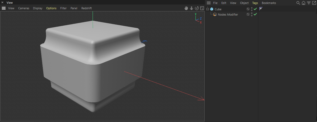 Here, the Node network created within the Nodes Modifier group results in new subdivisions in the center of the cube and models an elevation in this area. All settings on the cube, as well as within the Asset group, remain parametric and can still be adjusted or even animated at any time.
The result documented in the figure above can be achieved with just a few Nodes that need to be connected to the Geometry input within the Nodes Modifier group. First, we use Selection Nodes to select only the perpendicular polygons on the geometry. In the second half of the network, Inset and Polygon Bevel are used to shrink the selected surfaces and eventually curve them outward. The Geometryresult of all these calculations is connected to the Geometry output of the group and thus becomes visible at the object in the Object Manager.
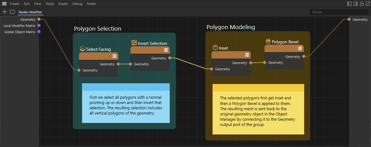 As usual, selections can also be used to restrict modeling commands only to certain sections of the geometry.
The colored highlights and comments in the figure above were created with Scaffolds and Notes and are provided here only for clarity and commentary on the Node graph. You can also have this example loaded by clicking on the file icon below.
Another advantage of the Asset Construction groups is that they can be saved directly in the Asset Browser under their own name by calling Convert To Asset... in the Assets menu of the Node Editor. This way, you can access this new feature in the Asset Browser at any time and use it in other projects in a flash.

Test circuits by section
Testing sections of the circuit can be particularly helpful when using the asset construction groups, through which new geometry will be created, changed or, for example, supplemented by selections. Imagine, for example, that several selection and modeling steps are carried out one after the other. If the result of the circuit does not meet your expectations, you would normally start troubleshooting which Node may be producing the wrong results. This troubleshooting can be dramatically accelerated if the Geometry output after each Node can be displayed. This is possible with all Nodes that provide a Geometry output. These Nodes offer the Geometry output command in their context menu (this appears after right-clicking on the Node). This causes the Geometry output of this Node to be connected directly to the Geometry output of the asset construction group. Any existing connections to this output will automatically be removed.
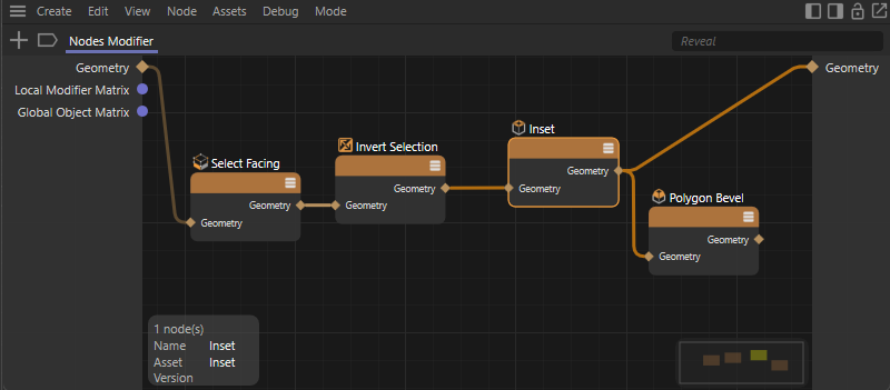 Here, Geometry output was called for the Extrude inside Node in order to pass its result directly to the Geometry output of the group.
As can be seen in the image above, to test the first Nodes, the geometry result of the Extrude Immer Node was forwarded directly to the Geometry output of the group by calling the Geometry output command. If the asset has already been assigned to a polygon object in the Object Manager, the result can be viewed directly in the Viewport. Calling up Geometry output again, this time for the Polygon Bevel Node, will automatically remove the connection to the Extrude Inner Node and reactivate the calculation of the entire circuit for the geometry calculation. Since Geometry output can also be called up via the Q shortcut for a selected Node with Geometry output, the connection and removal of geometry links to the Geometry output of the group can be switched very quickly.
Please note that Geometry output is only available if you are within an asset construction group or even a simple Node group that has a Geometry output and if a Node is selected that provides a Geometry output. It is only possible to process a single Node at a time. Therefore, make sure that only one Node with Geometry output is selected when using the Q shortcut.
Add User Data
As the above example shows, Assets can be used to very quickly create functions that can be used to individually expand the repertoire of modeling functions, for example. However, it may be somewhat inconvenient that the Node Editor must always be opened first in order to change parameters. To do this, double-click the Asset group in the Object Manager. This opens the Node Editor even if you are working only in Cinema 4D's default layout, for example. In the Node Editor, the value for Inset or for the Offset of the Polygon Bevel Node, for example, can then be changed directly at the corresponding Nodes. However, if you want to make certain values available as a dialog on the Asset, this is also possible with a few simple steps. This means that there is no need to open the Node Editor and the corresponding settings can be made directly after selecting the Asset in the Object Manager via the normal Attribute Manager, just as you are used to doing with other objects. To do this, proceed as follows:
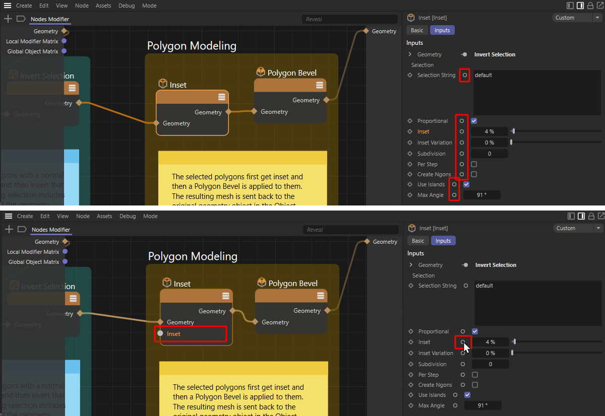 Node parameters that are displayed in the Attribute Manager can be added directly as Node inputs by Ctrl-clicking on the circles behind the parameter names.
As shown in red in the upper half of the figure above, small circle icons are displayed behind all Node parameters that can be operated via the Attribute Manager. By Ctrl-clicking on such a circle, an input matching the parameter is applied to the Node. As you can see in the lower half of the figure, we have created an input for Inset at the Inset Node here as an example. This parameter is useful for operating from outside the Node Editor to control the width of the bulge on the object. Using the same principle, you can also create parameter inputs at the Polygon Bevel Node, for example, which you also want to make available for external operation.
The following figure shows how we can now actually turn these parameter inputs into User Data. To do this, inputs must be created for these parameters at the Asset Construction group. As noted in the top half of the image, to do this, drag a connection from the Inset input to an empty area of the Node Editor and release the left mouse button there. A context menu appears where you select the Add New Input command.
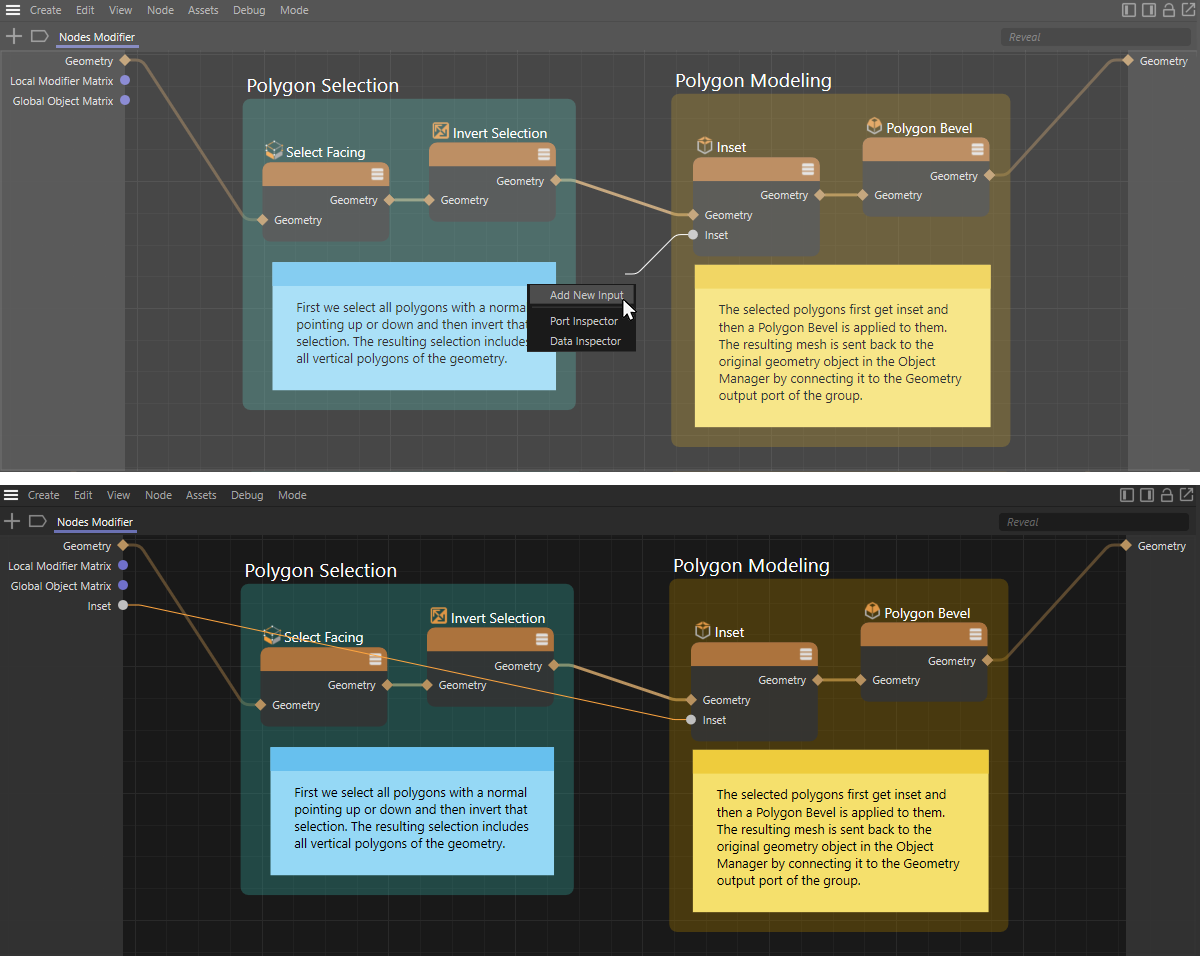 These images show the addition of a new User Data input to the group, based on an existing Node input.
The result of this action is that an input matching the Node input is created at the Asset group and a connection is automatically created between the Asset input and the input at the Node (see lower half of the figure above). Since this connection inevitably runs through other Nodes, the clarity of the graph can be improved by inserting Wire Rerouters (see the following figure). To do this, perform Shift+Ctrl clicks on a connection. The resulting Rerouters can be moved with the mouse as desired and are thus suitable for shaping the course of the connection.
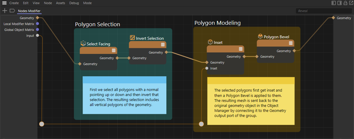 By inserting Wire Rerouters, the courses of connections can be shaped individually to prevent overlaps with Nodes and other elements in the Node Editor.
As can be seen in the figure above, the Wire Rerouters provide more clarity in the Node network. Unnecessary Rerouters can be removed at any time by clicking on them and using the Del key, without removing the connecting line that runs through them at the same time.
Since in our case it is a connection to an input on the Asset group, however, there is another option to optimize the clarity of the Node graph. To do this, remove the Rerouters you created at this connection again and then drag the name Inset from the left Asset group's input side directly into the Node Editor. This creates a so-called Floating IO Node, which now makes this group input directly available at its output side. As shown in the following figure, this allows us to provide the Inset value right next to the Inset Node, saving us the long connection to the left input side of the group.
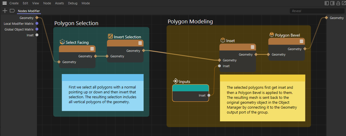 With a Floating IO Node the inputs of a group can be connected directly within the network.
If you now click on the Nodes Modifier Asset in the Object Manager, you should get the Inset value in the Attribute Manager, which you can now also operate there normally (see the following figure).
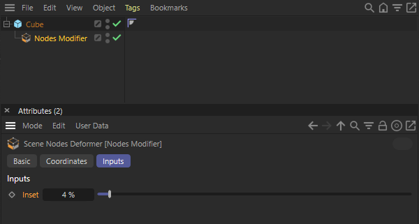 As usual, selections can also be used to restrict modeling commands only to certain sections of the geometry.
Another option for creating your own operating dialog is via the entries in the User Interface group in the Asset Browser. All information is summarized on this page in the documentation. You will also find further examples of how to create individual control elements.
In the User Interface group, you will find all common data types and control elements, such as sliders or option boxes, and can drag them directly from there into the left-hand column of a group or, for example, a Node modifier. This has the advantage that you can also create input options for data without the corresponding ports already being available on the Nodes of your circuit. For example, you can add options, numerical values or menus to the dialog of your asset, which can then be evaluated within the circuit or used for pre-calculations. Some of these operating elements, such as drop-down menus, allow the use of a variable number of entries. In these cases, further settings can be found in the Resource Editor (see the following section).
Using the Resource Editor
As explained in the previous section, User Data for the parameters that are directly available as inputs to Nodes can very easily be created as group inputs and thus made available to a user for operation. In some cases, however, it can also be helpful to offer the user your own values for operation, which are then to be processed within the Node network. In such cases, use the Resource Editor, which can be opened by right-clicking in the grid of the Node Editor and selecting Edit Resource... (see the following figure)
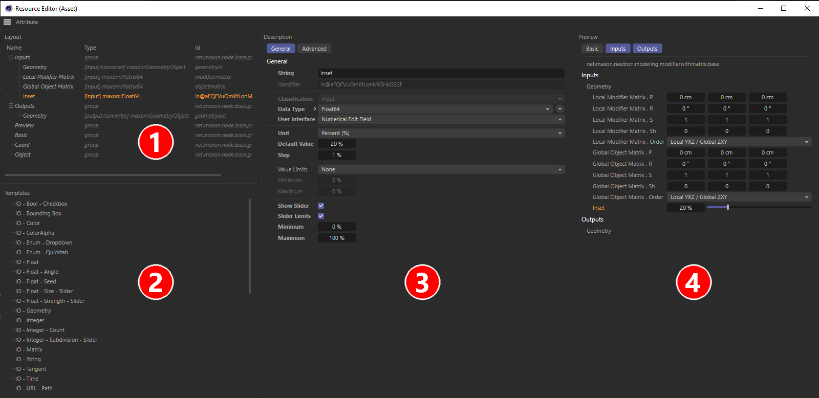 The four areas of the Resource Editor.
As you can see in the figure above, the Resource Editor offers four areas, which we will briefly explain here in terms of their function:
- Here you can see all inputs and outputs of the group. If you have already created several inputs according to the method described above, you can rearrange their order within the Inputs group here as you wish. This also affects the order of the parameters as they appear in the Attribute Manager. Here you can also create new, own inputs by dragging the desired data type from the area at number 2 into the Inputs group.
- Here you will find a list of typical data types, such as Color for a color input field, Integer for drop-down menus or integer value inputs, and Float for floating point values. Dragging the desired data type into the Inputs group at digit 1 automatically adds a corresponding input to the group and thus also generates a new parameter for input in the Attribute Manager. By double-clicking on the name of a data type in the list at number 1, its name can also be changed, which is then also used as the name for the corresponding parameter. All settings regarding units, user interface or e.g., value limits of a parameter are made in the settings area at number 3.
You will also find entries for a Separator or a Group in the list at number 2, which you can also drag into the Inputs area at number 1, in order to also be able to structure the display of many parameters in the Attribute Manager. - If an input is selected in the list at number 1, you will find all settings for it here. For example, the permissible value range for inputs can be limited here, a unit for numerical values can be activated, or a preset value can be specified.
- This area is intended only as a preview and shows you the representation of the Input values as a user would see them in the Attribute Manager. This can be used, for example, to check the user interfaces or the unit used for a numerical value.
After you have made additions or changes to the entries of the Inputs group in the Resource Editor, you can simply close it again. Change will be applied automatically and you can proceed with dragging new connections from these inputs directly in the Node Editor.
Detailed descriptions of all possible data types that are suitable as user data and further examples for using the Resource Editor can be found on this page.
Example for creating your own generator
One of the core concepts of Cinema 4D is the use of Generators in the Object Manager. Think of the Subdivision Surface object, for example, or the various generators that can be used to process splines into polygon geometry, such as the Extrude object.
Generators use the objects that have been grouped under them and calculate something new from them. This principle can also be used for custom capsules based on a Node Mesh. Let's take a look at this using a brief example:
The capsule to be created should evaluate the polygon geometry of a Child object and subdivide it as required. The subdivision should be both rounded and non-rounded so that the user can smoothly mix the original and the rounded version of the Child object. This function is not currently included in Cinema 4D, so it offers us real added value for animation or modeling.
- Step 1: Drag the Node Mesh Asset from the Asset Browser into the Object Manager and assign a primitive cube object to it there, for example. The more angular this object is and the fewer polygons it has, the more obvious the effect configured below will be. If you subordinate an object that is already heavily subdivided and organically rounded, the effect will hardly be visible.
- Step 2: Double-click on the icon of the Node Mesh object in the Object Manager to open the Node Editor in Capsule mode and display the contents of the Node Mesh capsule, which is currently still empty. However, the Geometry output of the capsule is already on the right, to which you must send the newly created or modified geometry in order to make the result visible in the view window. In our case, we want to evaluate the Child object in the Object Manager. To make this available in the capsule, right-click in the Node Editor and select Add input > IO object - Child object in the context menu. A new input area now appears on the left-hand side of the Node Editor, in which a port provides the data of the Child object in the Object Manager. The individual properties of the Child object can be queried separately using the arrow symbol next to the port (see illustration below).
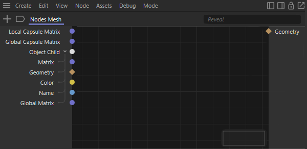 The Node Mesh capsule with the added input for Object - Child object.
- Step 3: After double-clicking in the Node Editor, select a Transform Geometry Node from the Geometry Utility category. Connect its Geometry input to the corresponding input of the capsule and establish a connection between the Matrix input of the capsule and the Transform input of Transform Geometry. This gives you a geometry with globally converted point coordinates. This is important so that the Child object of the capsule can later be moved, rotated or scaled as required in the Object Manager and the geometry calculated by the capsule behaves synchronously. Without this step, the point coordinates would only ever be passed on locally to the capsule.
- Step 4: Now create two Subdivision Nodes, which you can find in the Geometry modifier Asset Browser category. Add the term hard to the name of the first Subdivision Node and soft to the second. This is intended to express the different configuration of these Nodes. Both add the same number of subdivisions to the geometry, but only subdivision - soft should also calculate a smoothing or rounding of the subdivided geometry at the same time. This is achieved by activating the soft option on both Subdivision Nodes, but setting the angle to 0° on subdivision - hard. This means that the original shape of the geometry introduced is completely retained. On lower parts - soft is also active, but in conjunction with an angle of 180°, which results in a complete rounding of the entire geometry. The Geometry inputs of both Subdivision Nodes are finally connected to the Geometry output of Transform Geometry. The trick with the Angle value ensures that the point sequence is identical for both Subdivision Nodes and we can therefore create a mix between the point positions of both geometry versions.
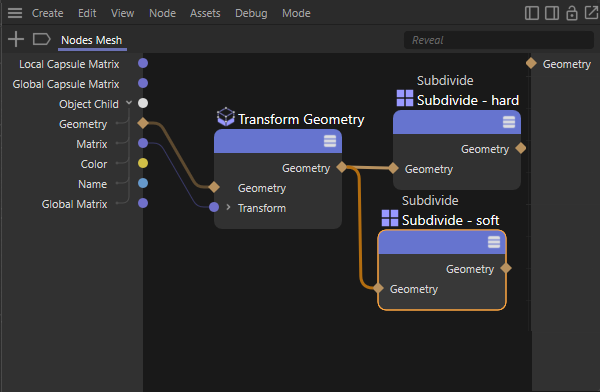 Conversion of the local geometry into a global geometry and calculation of two different subdivision types.
 On the left the configuration of the hard subdivision, on the right the configuration of the soft subdivision. The only difference is the use of the Angle value. This ensures that the sequence of points is absolutely identical for both types of subdivision.
- Step 5: We now have two versions of the original geometry, one with and one without rounding subdivisions. We add two Get Geometry Properties Nodes from the Geometry Utility category and one Mix Node from the Data Structures category to the circuit. We connect the Geometry outputs of the Subdivision Nodes to one of the Geometry inputs of the Get Geometry Properties Nodes. These two Nodes each use the Positions Type setting so that we receive all point positions at the Array outputs of these Nodes. We connect the point array of the hard-divided geometry to the Array input of the Mix Node. The point array of the rounded subdivided geometry is connected to the Target Array input of the Mix Node. We can then use the Mix value of this Node to mix continuously between the two states. The Linear mode on the Mix mode is useful for this, so that you can mix linearly between the two shapes.
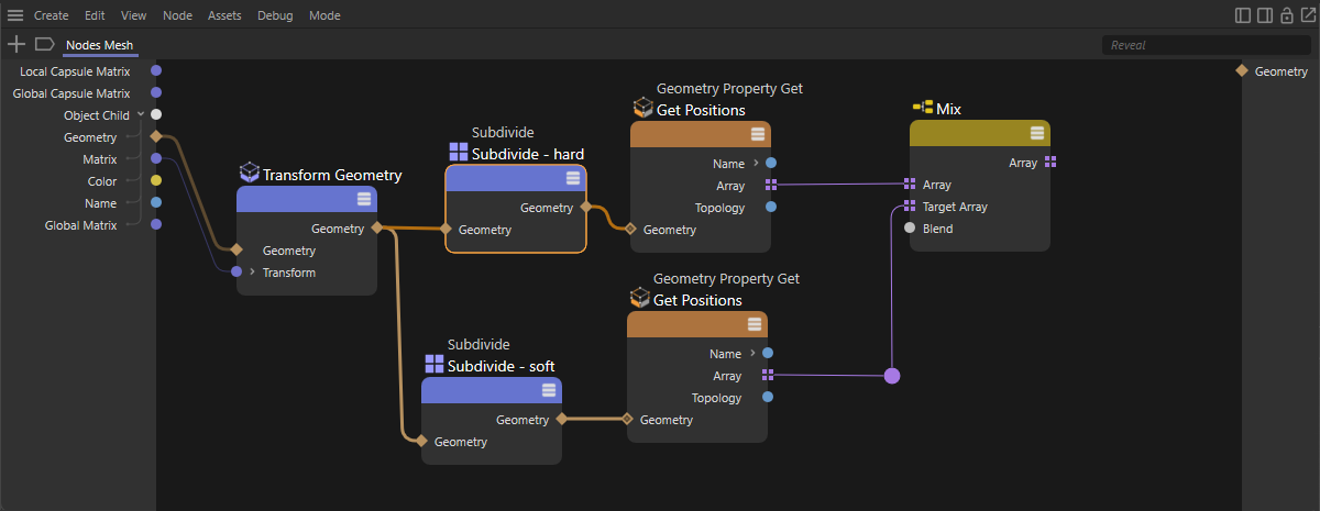 A Mix nNode calculates a linear blend between the two versions of the subdivided geometry.
- Step 6: Now there is not much left to do. The Mix Node supplies the newly placed point positions at its array output, which now only need to be written back to become visible on the geometry. To do this, create a Geometry Property Set Node, which you can find in the Geometry Utility category, and configure it with the Positions type and an activated Array mode. Accordingly, its Array input can now be connected directly to the Array output of the Mix Node. Also draw a connection between the Geometry output on the hard Subdivision Node and the Geometry input of Geometry Property Set. In this way, the new point positions are written back to the geometry of the Child object. The Geometry output is finally sent to the Geometry output of the capsule so that the result can be seen in the scene. If you now change the Mix value on the Mix Node between 0% and 100%, you should be able to blend smoothly between the original and the rounded subdivision surface shape of the Child object. Below you will find an illustration of the circuit currently described.
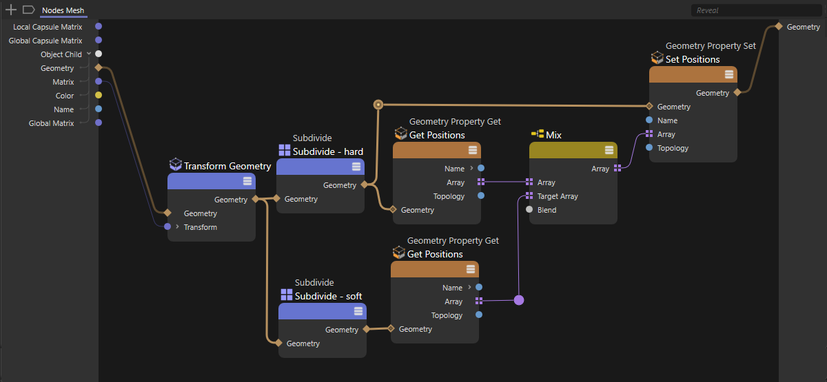 Write the mixed geometry back to the Child object and output the geometry for display in the Viewports.
Optimizing the Generator capsule
The usability of our capsule can now be made even easier by removing the defaults for the number of subdivisions and also the mixing value and thus making them directly available as parameters in the Attribute Manager when the capsule is selected in the Object Manager. To do this, you can either add the required input ports to the Nodes directly (as shown in this example ) and then define these as inputs on the capsule, or you can first create your own capsule inputs and then connect these to the corresponding Node parameters. In this example, we choose the second variant and proceed as follows:
- Step 1: Right-click in the left input area of the capsule circuit and select Add input in the context menu. The various data types are available there. We select Integer, as this value should specify the number of subdivisions at the two Subdivision Nodes and this must be an integer value. Double-click on the name of the new input in the Node Editor so that you can enter your own name for this value. Select Subdivisions, for example.
- Step 2: Repeat this to add another input, this time to control the Mix value of the Mix Node. This time we need a percentage value, i.e., the Floating Point data type. Then name this input, e.g., with Smoothing.
- Step 3: We have created two new inputs on the capsule that are suitable in terms of data type, but we should still adapt them with regard to their control elements and also with regard to the permitted value range, so that a user cannot, for example, enter arbitrarily high values for the subdivisions, which could then lead to the computer freezing. To do this, right-click again in the input area of the capsule and select Edit resource... from the context menu.
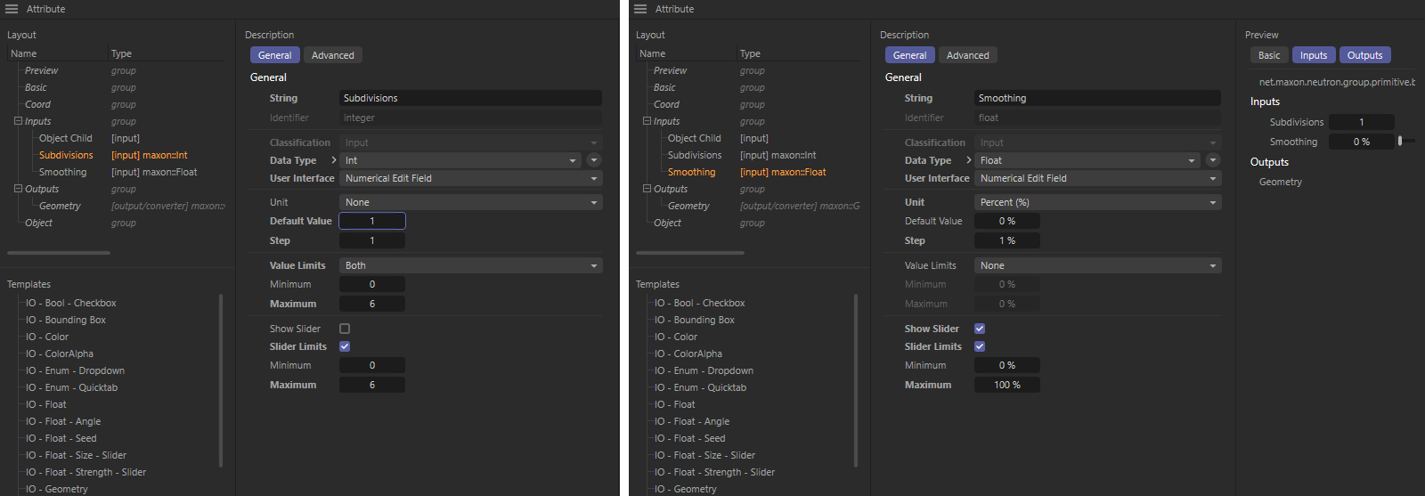 Configuration of the two new inputs in the Resource Editor.
- Step 4: In the Resource Editor, you will find the list of inputs in the top left-hand corner, where our two Subdivision and Smoothing parameters also appear. Select these and then adjust their settings in the middle section of the Resource Editor, as suggested in the illustration above. The Subdivision value is given a default value of 1 with an Increment of 1, which is used when using the arrows in the input field. We are also restricting the permissible values to between 0 and 6 for the time being.
For the Smoothing value, we activate Percent as the unit and set the default value to 0% and the increment to 1%. We also activate a Slider and limit its values between 0% and 100%. As the Value Clamp remains switched off, values outside this range can also be entered in the Value field. For example, we can then also use negative values to obtain an inverted mixing effect.
On the right-hand side of the Resource Editor, you will see a preview of our input values and how they will be presented to the user. You can try out value entries or controls there at any time, for example, to check whether the configuration in the middle section of the Resource Editor produces the desired effect. At the end, simply close the Resource Editor again. - Step 5: In the last step, we need to connect our capsule inputs to the corresponding ports of the Nodes. To do this, first select the two Subdivision Nodes(left-click on the first Node and Ctrl-click to add the selection of the second Node) and Ctrl-left-click on the circle behind the Iteration parameter in the Attribute Manager. This creates Iteration inputs at both Subdivision Nodes. Connect these to our Subdivision input.
Proceed in the same way with the Mix value of the Mix Node and then connect this port to our Smoothing input of the capsule. Our generator capsule is now ready. Below you will find the scene of this circuit and an example animation.