Trackers
An Object Tracker needs a corresponding Motion Tracker (otherwise all settings will be grayed out). The link to the Motion Tracker is displayed in this field. If only one Motion Tracker is present in the scene when an Object Tracker is created, this link will be created automatically. Otherwise the currently selected Motion Tracker object will be linked. Normally, this field will be filled out automatically either way (unless you experiment with several Motion Tracker objects at once and want to determine yourself which one is linked).
There are two ways to solve a 3D object:
Geometry-assisted Solve
With this method, a 3D object is modeled (referred to as ,reference object’ in the following) that will follow an object in the live footage as precisely as possible. This object should be well marked with 2D tracks to make it easier to track. This can - but doesn't have to be - the same object that will be replaced by the 3D object in the footage (it should, however, be closely related). Assuming you want to replace a person's thumb with a robot thumb. You can track the thumb, which would be difficult because it has very few visual characteristics that are easy to track. Instead, you can use a checkered pattern (in the real world you would use a special tracking glove in the live footage) attached to the thumb that moves as the thumb does.
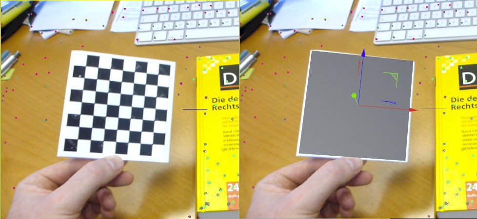 A congruent plane was positioned over the checkerboard pattern.
A plane was created (make a note of the frame; later the reference object must be made a Child object of the Object Tracker at this frame if you want it to move with it) as a reference object and positioned to lie over the checkerboard pattern. The reference object has the same size as in the live footage (in this example 14 cm x 14 cm, for example).
This layer is then placed into the Object Tracker's Geometry Object field (Tracker tab). The following must be true for the geometry object:
- It must cover all object Tracks, if possible
- The object should be modeled and positioned as precisely as possible in the region of the object Tracks (to fit the shape of the object in the live footage). This is easy to do in the example above because a simple plane can be used. However, if an actor's face has to be tracked, e.g., to replace it with a mask, the reference object should reflect the actor's face as precisely as possible, preferrably using exact facial measurements.
Note that a focal length must be defined for the Motion Tracker object (Reconstruction tab) when using this method.
The following happens when you click on the Run 3D Solver for Object button:
-
Rays will be emitted, at the time in the footage as specified above, into the scene from the camera's angle of view and the points of intersection will be calculated with the reference object.
-
These points of intersection can be used to assign 3D positions to 2D Tracks in the object space.
-
Position and rotation of the reference object in relation to the camera can be calculated for other segments in the footage using a combination of 2D Tracks and known 3D positions.
- Keyframes will be created for the Object Tracker to give the object the correct movement in relation to the camera (which themselves may already be animated via a previous camera solve). If the solve was successful, the matching 3D object must be made a Child object of the Object Tracker so it moves correctly over the entire length of the live footage. This is the best way to see if the 3D object solve was successful and if the quality is high enough.
The geometry-assisted solve requires fewer Tracks than without geometry. Many times, objects tracked in the live footage are very small and only few Tracks are needed. The absolute minimum number of Tracks for this method is 3 for each point in time (if you have 3 good Tracks (that must also lie on the geometry object from the angle of view of the camera), a simple plane can suffice as a reference object to create a 3D solve). More Tracks - in adequate quality - will, however, lead to more precise results.
By using a polygon object as a reference object, the scene will also be calibrated, i.e., you will not require a Motion Tracker Constraint tag (which is not required in conjunction with the aforementioned method), contrary to the geometry-free method described below.
Geometry-free Solve
Geometry-free solves (the Geometry Object field remains empty) creates a group of points for the Tracks (absolute minimum is 7 Object Tracks; the more Tracks with adequate quality, the better) that will initially lie in space with no defined scale or distance from the camera; this is similar to Camera Tracking as long as its solve has not yet been ,calibrated’ by a Motion Tracker Constraint tag.
This only means that the undefined group of points (which is first of all independent of any camera solve) must first be ,calibrated’ using the Motion Tracker Constraint tag. The axes and positions that you define here refer to the Object Tracker's coordinate system (contrary to camera solving which only uses the world coordinate system)! This means that when you create a polygon object to match the movement and make it a Child object of the Object Tracker, its position and rotation will be set to 0 so it is set to the Object Tracker's origin from where it will move along correctly.

All Tracks (Auto and User Tracks) from the tracked object are displayed in this list. This lets the Motion Tracker object recognize which Tracks should be used for camera tracking: all, except for those shown in the list.
The selections made here correspond with the selections in the Viewport.
The description of the list can be foune here in the Object Tracker object. The functionality is exactly the same.
This option enables or disables virtual keyframes for selected Tracks.
Normally, a User Track is created by creating a key and tracking it. This tracking uses the key saved to the pixel pattern, which, of course, changes over the course of the video as it moves farther from the frame. If the change is too great, the tracking will fail and you have to make adjustments manually. Virtual keyframes help with tracking by automatically adding new keys to the tracked section according to the settings below (contrary to manually-created keyframes - which are permanent - these virtual keyframes are dependent on the virtual keyframe settings, among other things, and can therefore change).
This will produce better tracking in most cases since changing pixel patterns can be compensated for by the virtual keyframes. However, it can happen that the virtual keyframes can shift from their original, manually defined footage position. If this happens, keys can be added manually.
Virtual keyframes are colored light blue in the Motion Tracker graph.
Here you can define the rules according to which virtual keyframes should be created. The following options are available:
- Frame Spacing: this creates virtual keyframes at regular intervals.
- Overwrite Error Threshold: a virtual keyframe will be created after the Error Threshold is exceeded (the Motion Tracker graph’s
 2D Tracking Errors mode will assist in the normal value range).
- Preemptive Error Threshold: a virtual keyframe will be created before the Error Threshold is exceeded. This is the more precise method compared to the previous method and offers the best quality.
- Multi: this will be displayed if multiple tracks with different virtual keyframe settings have been selected.
Internally, the difference to the previous key (corresponding to the Tracking direction) will be ascertained for each Track at each frame. If this difference is greater than the threshold value defined here, a virtual keyframe will be created. The smaller the value, the less modification that will be allowed compared to the previous frame and the more virtual keyframes will be created and vice-versa.
Frame Interval[-2147483648..2147483647]
Use this setting to define the temporal interval in which virtual keyframes should be created.
This setting can be used to change the color weighting of selected Tracks. A new Tracking will be created immediately. Details about color weighting can be found under Preferences: Weighting Red/Green/Blue.
In the Color Filter selection menu you can select from the following options:
- Luminance: The luminance from pre-R19 versions of Cinema 4D
- Red/Green/Blue: Use this option to emphasize a specific color channel
- Red/Green/Blue Expanded: These settings take the Red/Green/Blue a step further and set the color channels to negative values, e.g., so red can create an even higher contrast in front of a white background (see also Preferences: Weighting Red/Green/Blue). Colored markers will be enhanced in front of a background that contains a high amount of the marker color.
- Default: Sets the values in the Options menu to the defined color weighting.
- Use as Default: Sets the currently defined colors as default color weights (Options menu). Can be called up for the current footage after the first User Track has been created in order to make an optimized color filter available for additional User Tracks.
- Custom: Is available if you use custom values and sets corresponding color weights for the individual color filters (they can be opened by clicking on the small arrow next to Color Filter).
If Tracks are selected in the Viewport, they can be added to the list using this command. This can also be done per RMB: Assign to Object.
Removes selected Tracks for the Object Tracker's list. They will then be assigned to the Motion Tracker.