Redshift Nodes
In addition to the predefined Redshift materials, additional nodes are also offered that can be used to create completely individual material properties. These include, for example, nodes that can be used to load textures or calculate floating point values, vectors and colors. The corresponding Redshift nodes are divided into these categories:
If you want to create your own materials, the mechanisms available are similar to those for creating asset capsules with scene nodes. You will find explanations on these pages of the documentation, which primarily deal with the creation or modification of geometry.
For your own materials, you can define which of the material settings should be made available to a user directly in the Attribute Manager when they select the material in the Material Manager. Let's look at an example.
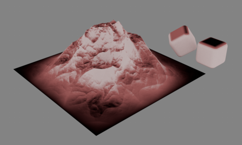 Example of a self-created Redshift material that evaluates the gradient of surfaces and assigns suitable color values. Horizontal areas remain black, vertical areas appear white, and gradients in between are given reddish tints. Example of a self-created Redshift material that evaluates the gradient of surfaces and assigns suitable color values. Horizontal areas remain black, vertical areas appear white, and gradients in between are given reddish tints.
|
|
We use a State node to read out the current surface normal under the pixel to be calculated and to determine the angle to the vertical. This angle is converted into color values via a Ramp node, which then color a landscape differently depending on its gradient, for example. It would make sense to specify limit values and possibly also an option to automatically make the color transitions hard. If, as in this case, several settings are to be made available, a Group node can be used for this purpose, to which the desired inputs are then created.
As can be seen on the left in the following illustration, there is a folder icon on the group that can be used to open the group and then display its currently empty content in the Node Editor. To leave this view again and view the actual circuit of the material outside the group, click on the term Mat in the upper path display of the Node Editor. This area is also highlighted in red in the following illustration. The right-hand side of the illustration shows a possible result, whereby an input and output for a floating point value can already be seen on the group.
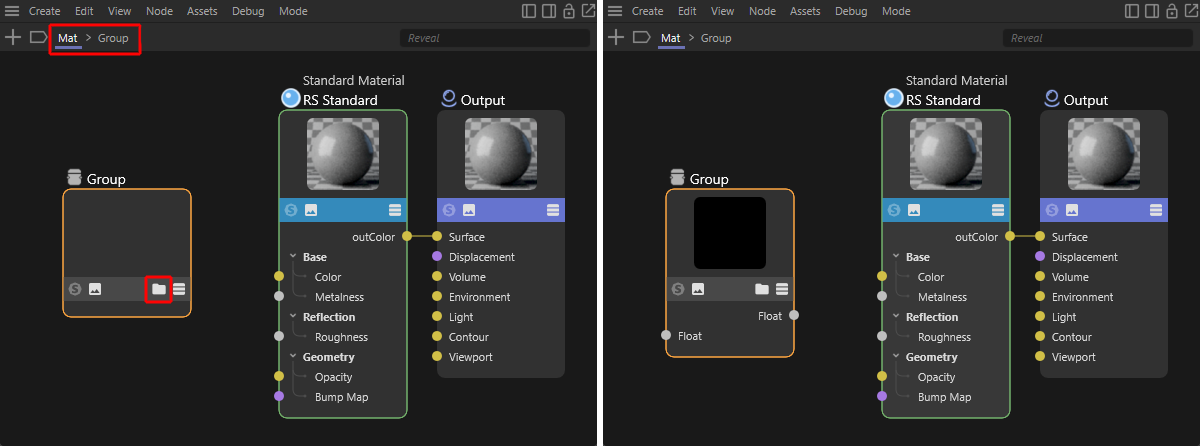
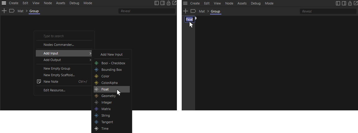
To create such inputs and outputs in the required data types on the group, open the view of the group by clicking on its folder icon (see left-hand side of the figure above) and then right-click in the nodes area of the group. In the context menu that appears, select the required data type under Add Input. In the following illustration, this is an example of a Float value that can be used, for example, to set percentage values or angles (see left-hand side of the following illustration). In the same way, you can also use an input option for a color (Color data format) or an option for activating or deactivating a function (Bool - Checkbox data format).
As the right-hand side of the following illustration shows, this causes a new input to appear in the left-hand area of the group. By double-clicking on the name of this input, it can be renamed as desired. This is then also the term that is displayed in the Attribute Manager.
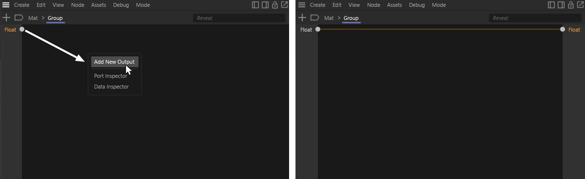
The evaluation and processing of the created group inputs can now take place directly within the group by creating corresponding Redshift nodes there and connecting them to the inputs, or you can forward the inputs directly to corresponding outputs on the group. The following figure demonstrates how such a pass-through can be created. As can be seen on the left-hand side, simply drag the input port into the circuit area of the group and drop it there by releasing the left mouse button. A context menu appears in which you can select Add New Output. As the following figure on the right-hand side shows, this creates a pass-through of the input value to a new output, which is automatically given the same name and the same data type.
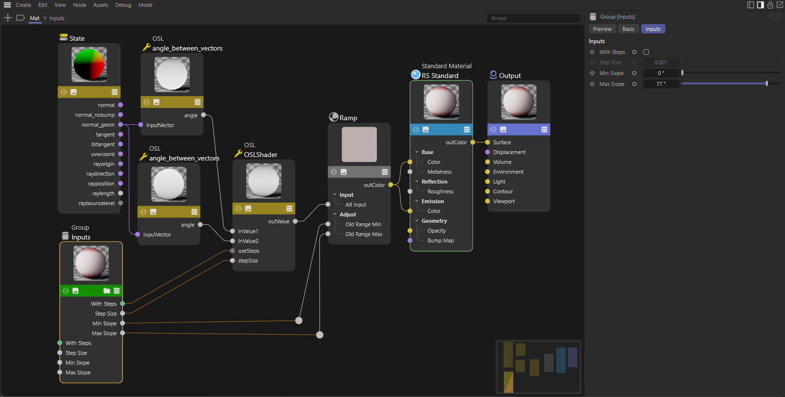
The following figure shows the complete circuit for the material, in which the outputs of the group are used at various points on the subsequent Redshift nodes to influence the calculation of the color values. Although the selection of the group shows the values offered in the Attribute Manager of the Node Editor, when the material is selected in the Material Manager, only the settings of the Standard Material used in the material are displayed in the Attribute Manager. This is because the node of the Standard Material is always declared as the Start Node by default. The Start Node of a circuit is always displayed in the Attribute Manager when the material is selected in the Material Manager. However, this setting can also be easily changed via the Nodes menu of the Node Editor and assigned to another node.
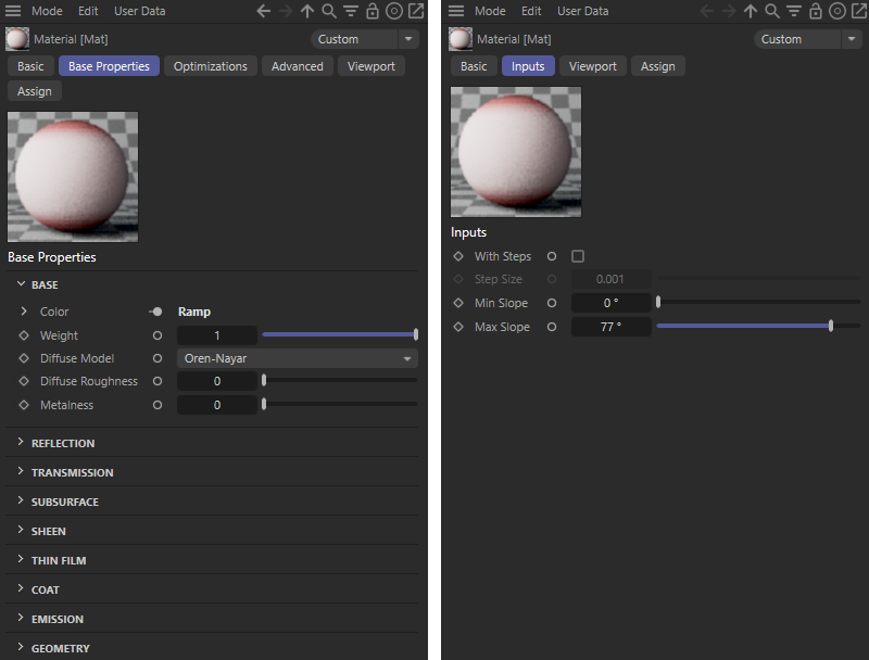
To do this, select the group with the value inputs in the circuit and then select Node > Start Node. The following figure shows the effect of this assignment. If the material is selected in the Material Manager, the settings of the group now appear directly in the Attribute Manager (see right side of the figure). The left side of the following figure shows the normal state of the circuit, in which the settings of the Standard Material appear in the Attribute Manager. You can return to this behaviour at any time by selecting the node of the Standard Material in the circuit and selecting Node > Start Node again. Only one node of the circuit can be defined as the Start Node at a time, so this automatically deactivates the Start Node assignment of the group again.
In any case, you always have direct access to all components and settings of the material by double-clicking on the material preview in the Material Manager to open the Node Editor.