Radiosity Maps
Radiosity Maps
When using the Secondary Method, Radiosity Maps are a quick and easy to use function that is particularly well-suited for preview renderings. The newer Light Mapping can also fast and also offer higher diffuse depth.
Simply put, illumination (Cinema 4D light sources, Area lights, sky) from the angle of view of the camera on polygons is calculated internally as special textures (Radiosity Maps) during the GI calculation. These are then used during the primary GI calculation for faster rendering. This method has several advantages and disadvantages:
Advantages:
- GI calculation is faster
- Radiosity Maps can be saved (see Auto Load) and re-used.
Disadvantages:
- The actual diffuse depth (number of diffused light reflections) is 1 (2 in the case of Area lights and/or skies), which darkens the rendering. This can in turn be offset by increasing the Gamma value to a certain degree.
- More memory is required
- When using simplified geometry (e.g., single-polygon walls without thickness), light can seep through. This can be prevented by modeling more realistically, i.e., giving walls a thickness.
Radiosity Maps can be made visible (
Visualize Shading).
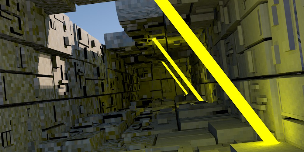
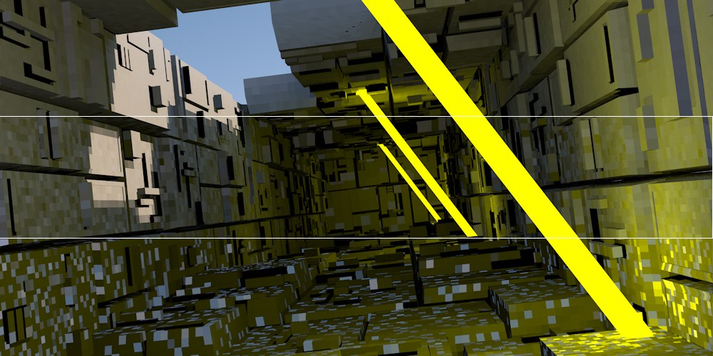
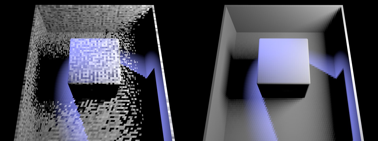 At left a Radiosity Map of poor quality, at right of better quality (made visible using Visualize Shading mode). Project setup: A blue Spot light shines from the top left and a white GI Area light from the right.
Radiosity Maps should have a light dispersion that is as homogenous as possible - as shown on the right of the image above.
Render Example, QMC+RM Method
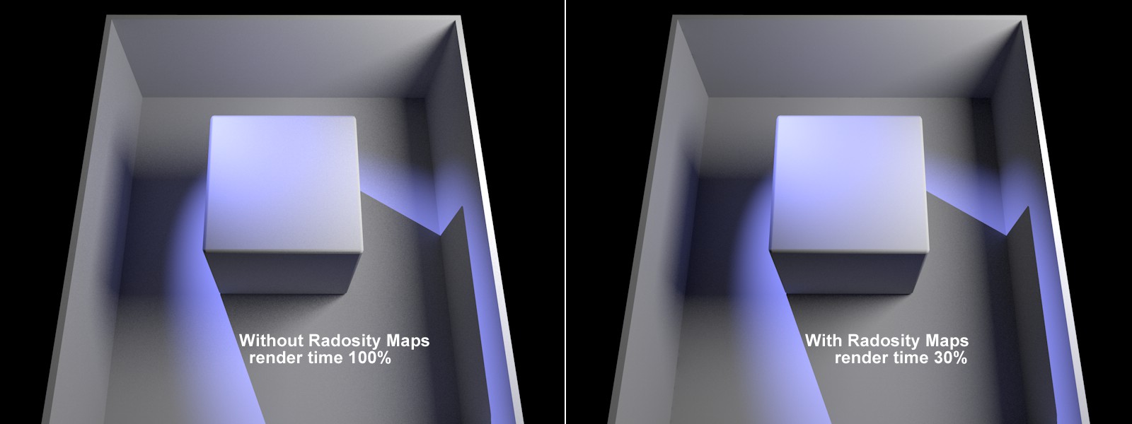 Render times and conditions differ according to the Project.
In the example above, the render time was greatly reduced while achieving a similar result. The use of Radiosity Maps darkens (reduces diffuse depth) the corners and shadows somewhat.
Radiosity Maps are supplemented during rendering, which means that when the camera views previously unseen regions, the Radiosity Maps will be updated and supplemented directly.
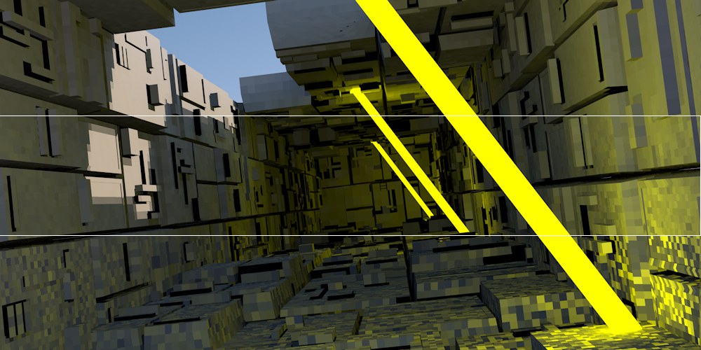
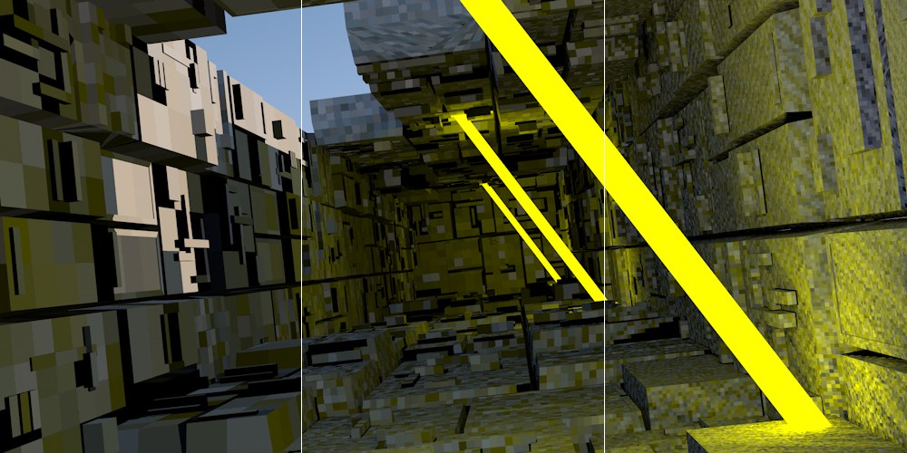 Increasing Map Density values from left to right, here with intentionally poor Sampling settings so the Texels are more visible (made visible using the Visualize Shading mode).
Use this setting to define the Radiosity Map resolution. The higher the value, the smaller the Texels will be (the small squares for which a uniform color/brightness is ascertained) and the higher the quality of the Radiosity Map will be (with correspondingly longer render times and increased memory requirements).
You can make Texels visible without complicated calculations by setting Mode Visualize Texels and rendering the Project.
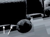
If the Texels are too large and light seeps through, as in the example above (they reach into regions that are actually covered by shadows), reducing the size of the Texels can help alleviate this problem.
 At left a smaller Sampling Subdivisions value, at right a larger value (made visible using the Visualize Shading mode).
This setting can be seen as a type of antialiasing for Texels (analog to pixels). A value of 2 will divide a square Texel into quarters and a color will be calculated for each quarter and averaged for that Texel. A value of 3 will divide the Texel into 9 equal parts and so on. Higher values will result in better quality and correspondingly longer render times and greater memory usage.
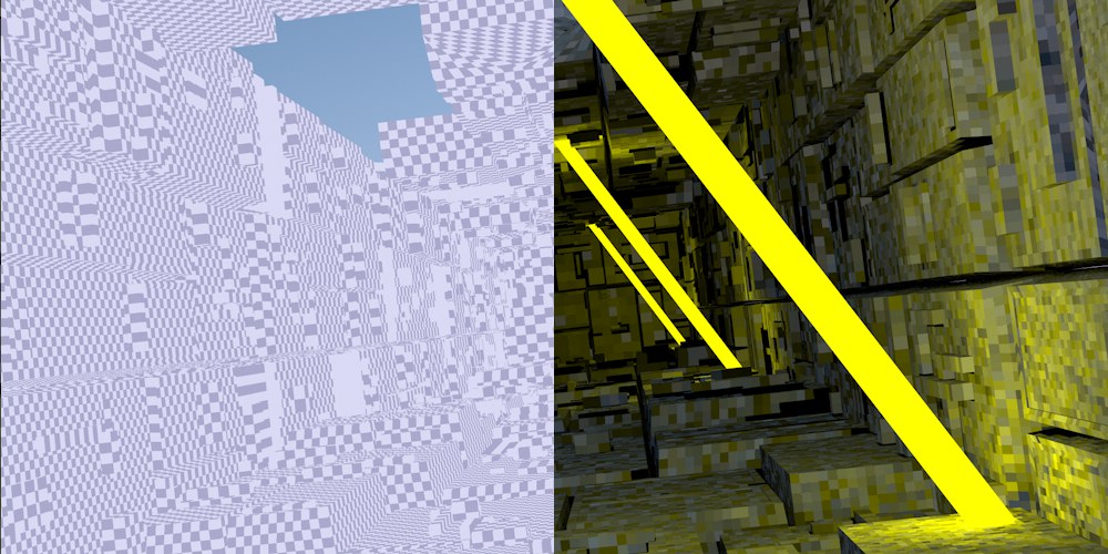 Left: Texel mode; right: Shading mode (made visible using Visualize Shading).
This is the normal render mode in which no Texels will be shown. This mode should be used for final renderings.
Displays the Texels in a grayscale pattern, independent of any illumination (see left half of above image).
This mode is the most comprehensive because it simultaneously shows the Texel dispersion and shaded Texels (in consideration of light, color and shadows, etc. (See right half of above image)).
Use these settings to display the shading on the front or back sides of polygons.
Radiosity Sampling Settings
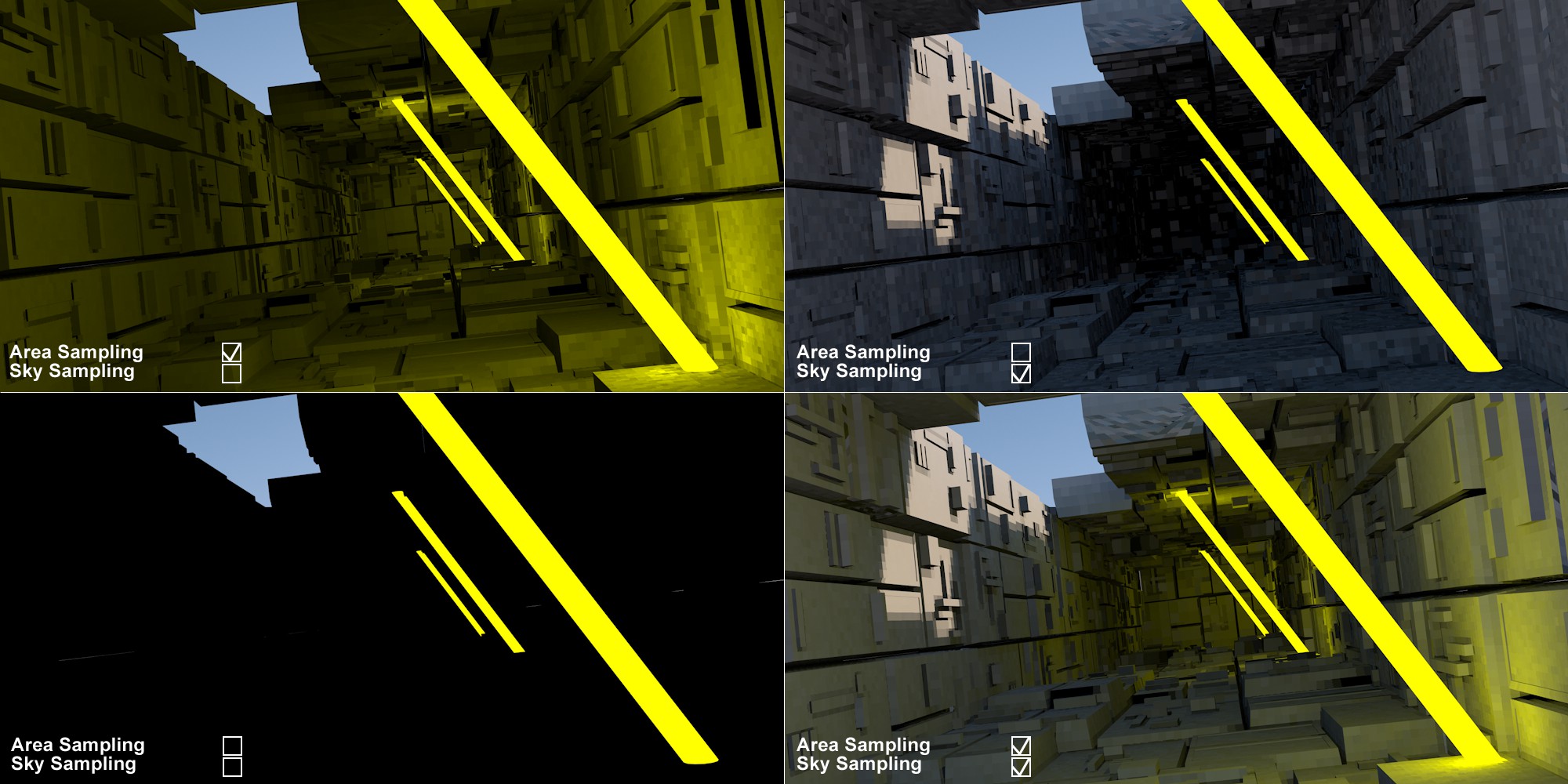 Various combinations of Area Sampling and Sky Sampling (made visible using Visualize Shading).
 Sample Count from bottom to top: 10, 100, 1000.
If this option is enabled, GI Area lights will also be included in the calculation of Radiosity Maps (and only for these!) and samples added (defined by the Sample Count setting). This option should always be enabled.
 Sample Count from bottom to top: 10, 100, 1000.
If this option is enabled, the sky will also be included in the calculation of Radiosity Maps (![]() Sky and
Sky and ![]() Physical Sky) and samples added (defined by the Sample Count setting). This option should always be enabled.
Physical Sky) and samples added (defined by the Sample Count setting). This option should always be enabled.